Determination of Material Properties like Permittivity and Density with Microwaves ()
1. Introduction
Microwaves can be defined as electromagnetic waves in the frequency range between 0.3 GHz and 300 GHz. The physical principles of their interaction with gases, liquids and solids are well known since a long time [1] [2] . Phenomena like scattering, reflection, transmission, refraction or polarization strongly depend on the electromagnetic properties of the material (permittivity, permeability, electric conductivity) and the geometry of the test object. Normally the electromagnetic material constants are strongly correlated to chemical, physical and mechanical material properties like chemical composition, material density, porosity, cure state, moisture content etc. [3] -[5] . Therefore, with the help of microwaves many properties of the test object can be retrieved in a non-destructive and, if needed, a contact-free way. In microwave domain usually only dielectrics and materials with low electric conductivity can be investigated. The interaction between the microwaves and the test object can take place in free space, i.e. in far field, where the waves are approximately plane, or in near field of the antenna with more spherical waves.
In contrast to normal ultrasonic testing (UT) based on piezoelectric effect no coupling medium is needed between the microwave antenna and the test object. This distance can be much larger than that in UT. Usually the used radiation power is very low (mW range) and thus harmless to humans.
2. Microwave Systems
Broadband microwave methods (radar) allow for setting temporal filters and thus for eliminating disturbance signals (clutter). However, there are many applications where no disturbing scatterers, e.g. the reinforcements in concrete structures, are to be expected. In these cases low-cost fixed frequency microwave sensors or radar sensors with a very limited bandwidth can be used. The paper describes the characterization of asphalt layers with microwaves with both an ultrawideband (UWB) device and with narrowband fixed frequency sensors.
The used UWB system was a ground penetrating radar (GPR) system from Malå (type Pro-Ex) which was equipped with a ground-coupled 2.3 GHz antenna for both transmission and reception.
Fixed-frequency sensors are more simple constructed and less expensive than the broad-band systems. Their frequency often falls into the royalty-free frequency bands like 2.45 GHz or 5.8 GHz (ISM-bands). Figure 1 gives an example of fixed frequency sensors which were used in monostatic mode (only one antenna for transmission and reception).
3. Materials
To ensure the quality of asphalt roads the density of the uppermost layer should be known. As example of use in the domain of quality assurance asphalt specimens with different densities have been chosen. The specimens were made from two asphalt types (SMA 11 S, AC 16 BS) and were positioned on wooden chip boards. The dimensions of the completely dry specimens were: length 31 cm, width: 26 cm, thickness: 4 cm (SMA 11 S) and 6 cm (AC 16 BS). The experiments were run in the antenna near field whose length is approximately given by r < 2d²/λ (d: largest dimension of antenna, λ: wave length).
4. Experimental Results and Discussion
4.1. Broadband Measurements
The measuring results with the GPR show an approximately linear relationship between the signal amplitude in

Figure 1. Microwave-sensors developed by Georgian (Caucasus) research institute RPC with fixed frequency 2.45 GHz (right) and 5.8 GHz (left) equipped with halfwave-dipole-antennas.
time domain and the material density of the asphalt layer (Figure 2). Normally the permittivity is increasing with increasing density in nearly linear manner. Thus according to the Fresnel-equations it is to be expected that the reflection coefficient is increasing with density, too [1] [2] . Indeed, this behavior has been observed in earlier investigations with GPR [6] . However, the GPR-measurements in Figure 2 exhibit the reverse behavior.
To explain this finding a multilayer model developed earlier [7] has been applied. For plane waves and normal incidence it takes into account all transmitted and reflected plane waves, i.e. all interference effects, inside a multilayer system characterized by the complex permittivities (including absorption effects and possible electrical conductivities) and thicknesses of the layers. The amplitudes of the backscattered radar signals in time domain have been calculated exemplary for a variety of thicknesses d and permittivities ɛr.
The calculations have been done for a four-layer system consisting of: 1) antenna, 2) lift-off (air gap, 1 mm), 3) asphalt and 4) chip board (ɛr = 2.5) resp. asphalt (ɛr = 6) within the frequency band of 1.2 GHz - 3.4 GHz. In Figure 3 it can be seen that the magnitude (absolute value) of the reflection coefficient decreases with increasing permittivity of the asphalt layer in a limited permittivity domain even if the frequency bandwidth is relatively big. Hence, due to these interference effects and due to the close correlation of the density with the permittivity, the magnitude can decrease with increasing density. If the bandwidth is further increased the minimum gets weaker and finally disappears. If there is another asphalt layer (instead of the chip board) with a permittivity close to that of the 1st asphalt layer and lying under the 1st layer, the minimum disappear (red curve in Figure 3) since the interference effects are now much less pronounced. So in real roads which are constructed of three or more asphalt layers, no drop but an increase in amplitude is to be expected as has been shown in [6] . In every case after performing a calibration the asphalt density can be determined with a broadband microwave device.
4.2. Narrowband Measurements
In the example given above the lift-off was quite small. Other measurements with a bigger lift-off have been

Figure 2. Amplitude (relative units) vs. volume density for asphalt specimens measured with GPR with broadband 2.3 GHz antenna.

Figure 3. Calculated maximum magnitude of microwave signal in time domain for a variation of permittivity (real part) ɛr for the four-layer system (see text), blue: asphalt layer lying on chip board, red: asphalt layer lying on another asphalt layer.
performed with the less expensive narrowband sensor incl. a dipole antenna (Figure 1, right). A strong dependence of the measuring amplitude on the lift-off has been observed (see Figure 4 for asphalt type SMA 11 S) since it acts like an additional layer which influences the wave propagation. The curves are oscillating with a periodicity of half wave-length. When the measuring points are plotted vs. density it can be found that some lift-off domains are more favorable than others (Figure 5). The less favorable curves exhibit a maximum or minimum resulting in ambiguities and a reduced sensitivity with respect to permittivity changes of the test object. A clear change in curve slope is unfavorable, too, while the curves measured at a lift-off around 6 cm exhibit a nearly constant slope and thus a nearly linear behavior (see Figure 6 for both investigated asphalt types).
The influence of the lift-off on the measuring voltage has already been observed earlier [8] [9] . It can be simulated and qualitatively reproduced with the same multi-layer model as mentioned above. In Figure 7 and Figure 8 the layers were: 1) semi-infinite space (ɛr = 1), 2) layer consisting of varying lift-off (ɛr = 1), 3) layer of material with permittivity varying between ɛr = 4 and 8 and 4) semi-infinite space (ɛr = 6), always for 2.45 GHz. With increasing permittivity—corresponding to an increasing material density—the curves in Figure 7 are shifted to the left side in accordance with Figure 4. For Figure 5 and Figure 8 a qualitative compliance between experiment and theory is found with regard to the scattering of the mean magnitude and the shift of its maxima and minima in x-axis.

Figure 4. Measured voltage vs. lift-off (SMA 11 S) measured with sensor in Figure 1.

Figure 5. Measured voltage vs. density for different lift-offs (SMA 11 S) measured with sensor in Figure 1.

Figure 6. Amplitude vs. volume density for asphalt specimens measured with fixed frequency sensor (2.45 GHz, Figure 1) and dipole antenna (lift-off 7 cm).

Figure 7. Calculation of the real part of reflection coefficient (narrow band) vs. lift-off for permittivities (real part) varying between ɛr = 4 and 8.
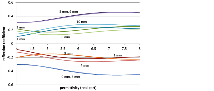
Figure 8. Calculated curves of the real part of the reflection coefficient (narrow band) vs. real part of permittivity of layer 3 with the lift-off as parameter (varying from 0 mm to 10 mm).
Thus it could be shown that it is possible to measure the density of a solid material with a low-cost microwave sensor provided that a calibration is performed and the lift-off is carefully adjusted.
5. Conclusion
The results described above show that there are diverse possibilities to measure the material properties like density nondestructively and contact-free with microwave devices. These encompass both narrowband and broadband devices. Normally a narrowband device is less complex and lower-priced than a broadband one, but it doesn’t allow for temporal windowing to eliminate disturbing echoes. These may originate from diverse structural elements of the test object, e.g. from the common steel reinforcements in concrete structures. Particularly for narrowband systems interference effects can occur resulting in partly low sensitivities or ambiguities of the microwave measuring quantity as a function of the material property and geometry. Here the lift-off or air gap between the antenna and the test object can play an important role. It is therefore advisable to maintain a constant lift-off and to optimize it in order to get the best sensitivity with respect to the material and geometrical properties of the test object. If the quantitative knowledge of these properties is wanted a calibration has to be performed. It is necessary to check thoroughly every potential application if a narrowband measurement is sufficient or if a broadband measurement has to be carried out.