Performance Enhancement of Discrete Multi-Tone Systems with a Trigonometric Transform ()
the CP and  is the
  channel impulse response. Let
  be the
Let Δ be the transmission delay of the signal between the transmitter and the receiver and let
 (1)
(1)
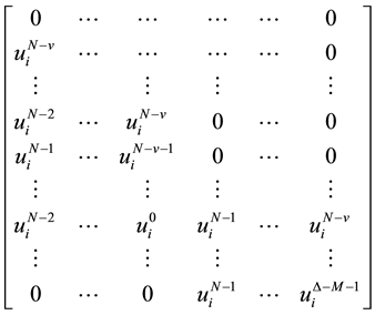
be the convolutional matrix of the DMT symbols ,
,  and
and . Define the
  matrix
 , where
  and
and  are,
are,
respectively, given by:
 (2)
(2)
![]() (3)
(3)
Matrices ![]() and
and ![]() of size
of size ![]() are, respectively, given by:
are, respectively, given by:
![]() (4)
(4)
![]() (5)
(5)
Let ![]() be the
be the ![]() convolution matrix of the CIR and TEQ given by:
convolution matrix of the CIR and TEQ given by:
![]() (6)
(6)
For the conventional DFT-DMT system, the channel input sequence ![]() at the output of the IFFT block, as shown in Figure 1, can be presented as [17], where
at the output of the IFFT block, as shown in Figure 1, can be presented as [17], where ![]() is the encoded bit stream.
is the encoded bit stream.
So, we can define the vector
![]() (8)
(8)
such that the inner product of ![]() with an N-points vector gives the kth FFT coefficient of that vector, where
with an N-points vector gives the kth FFT coefficient of that vector, where ![]() is the Hermitian conjugate transpose operator.
is the Hermitian conjugate transpose operator.
Let the near end crosstalk (NEXT) or additive white
![]()
Figure 1. DFT-DMT system model. xCP means remove the CP.
Gaussian noise (AWGN) vector be:
![]() (9)
(9)
Then the (N + M ‒ 1) × M AWGN or NEXT convolu- tion matrices with the TEQ, GAWGN or GNEXT is:
![]() (10)
(10)
![]() (11)
(11)
The received data contains the noise due to the ISI, ICI, AWGN, NEXT, and suffers from the effects of the channel. Now, we see the dependence of the received signal on the TEQ. The ideal received signal has no noise and is formatted to fit the demodulation scheme. In DMT modulation, this means that the received symbol has mi- nimal noise due to AWGN, NEXT, and ISI. We can de- sign the TEQ to process the received samples to achieve this target.
Next, we will express the desired signal as a function of the TEQ taps. The desired circular convolution of the ![]() symbol and the CIR in the kth sub-channel, after the TEQ and FFT, can be written as:
symbol and the CIR in the kth sub-channel, after the TEQ and FFT, can be written as:
![]() (12)
(12)
and the ![]() circulant matrix
circulant matrix ![]() is:
is:
![]() (13)
(13)
So, the received data ![]() can be rewritten as:
can be rewritten as:
![]() (14)
(14)
We then write ![]() for all k as
for all k as
![]() (15)
(15)
where E[・] is the statistical expectation operator and
![]() stands for model. The proposed SNR model is
stands for model. The proposed SNR model is
the ratio of the desired data, which excludes the effects of the noise including the ISI and ICI, to the difference be- tween the received data and the desired data.
Derive ![]() as:
as:
![]() (16)
(16)
where ![]() is an
is an ![]() matrix given by:
matrix given by:
![]() (17)
(17)
and![]() ,
, ![]() and
and![]() .
.
Similarly, derive ![]() as,
as,
![]() (18)
(18)
where ![]() is the noise variance, which is measured by the power of the noise with respect to
is the noise variance, which is measured by the power of the noise with respect to![]() ,
, ![]() is the toeplitz variance matrix of the NEXT and
is the toeplitz variance matrix of the NEXT and ![]() is the
is the ![]() identity matrix. Without loss of generality, define constraint set
identity matrix. Without loss of generality, define constraint set
![]() , so that
, so that ![]() becomes inde-
becomes inde-
pendent of ![]() over this constraint set. Matrix
over this constraint set. Matrix ![]() of size
of size ![]() is defined as:
is defined as:
![]() (19)
(19)
where ![]() are members of the vector
are members of the vector ![]() defined by Equation (8).
defined by Equation (8). ![]() is a
is a ![]() upper diagonal matrix de- fined as:
upper diagonal matrix de- fined as:
![]() (20)
(20)
![]() is a lower diagonal
is a lower diagonal
![]() matrix defined as:
matrix defined as:
![]() (21)
(21)
![]() and
and ![]() are Hermitian symmetric matrices. Now (15) becomes:
are Hermitian symmetric matrices. Now (15) becomes:
![]() (22)
(22)
The ![]() is a ratio of quadratic functions of
is a ratio of quadratic functions of![]() . The SNR model becomes equivalent to the SNR that could be measured at the output of the FFT in an ADSL system, when the ISI and ICI have been removed from the received signal.
. The SNR model becomes equivalent to the SNR that could be measured at the output of the FFT in an ADSL system, when the ISI and ICI have been removed from the received signal.
Using the SNR model, the number of bits per symbol that can be supported is:
![]() (23)
(23)
where ![]() and
and![]() , k is the sub- channel index,
, k is the sub- channel index, ![]() is the set of the indices of the used Ñ sub-channels out of N/2 + 1 sub-channels,
is the set of the indices of the used Ñ sub-channels out of N/2 + 1 sub-channels, ![]() is the number of bits per data symbol in the sub-channel k, Г is the SNR gap, and it is a function of several factors, in- cluding modulation method, allowable probability of error, gain of any coding applied, and desired system margin.
is the number of bits per data symbol in the sub-channel k, Г is the SNR gap, and it is a function of several factors, in- cluding modulation method, allowable probability of error, gain of any coding applied, and desired system margin.
Maximizing the number of bits allocated to a single channel, ![]() involves maximizing the argument of the log function. Since the log function is a monotoni- cally increasing function of a non-negative argument, maximizing its non-negative argument will also maxim- ize the function. Mathematical notation for this statement is:
involves maximizing the argument of the log function. Since the log function is a monotoni- cally increasing function of a non-negative argument, maximizing its non-negative argument will also maxim- ize the function. Mathematical notation for this statement is:
![]() (24)
(24)
This is the well-known generalized eigenvalue prob- lem [16] and the solution is the generalized eigenvector ![]() corresponding to the largest generalized eigenvalue
corresponding to the largest generalized eigenvalue ![]() of
of ![]()
![]() (25)
(25)
Hence, ![]()
where ![]() denotes the real part. The number of bits per symbol that can be supported in the case of the conven- tional DFT-DMT system with TEQ filter bank is:
denotes the real part. The number of bits per symbol that can be supported in the case of the conven- tional DFT-DMT system with TEQ filter bank is:
![]() (26)
(26)
Bits/symbol.
3. The proposed DST-DMT System
For the proposed DST-DMT system with TEQ filter bank, the channel input sequence ![]() at the output of the IDST block, as shown in Figure 2, can be presented as [18]:
at the output of the IDST block, as shown in Figure 2, can be presented as [18]:
![]() (27)
(27)
where
![]() (28)
(28)
and ![]() is the encoded bit stream.
is the encoded bit stream.
So, the defined vector in Equation (8) will be:
![]() (29)
(29)
such that the inner product of ![]() with an N-points vector gives the kth DST coefficient of that vector. Note
with an N-points vector gives the kth DST coefficient of that vector. Note
that in the above equation ![]() will be
will be ![]() for
for
![]() .
.
Depending on the defined vector in Equation (29) and
using the above algorithm, we can derive a new ![]()
corresponding to the largest generalized eigenvalue
![]() of
of ![]()
![]()
Figure 2. The proposed DST-DMT system model. xCP means remove the CP.
![]() (30)
(30)
Hence,
![]() (31)
(31)
where ![]() is the number of bits per data symbol in the sub-channel k. The number of bits per symbol that can be supported with the proposed DST-DMT systems implementing a TEQ filter bank is:
is the number of bits per data symbol in the sub-channel k. The number of bits per symbol that can be supported with the proposed DST-DMT systems implementing a TEQ filter bank is:
![]()
Bits/symbol (32).
4. TEQ Design Algorithm
The first derivative of (23) is:
![]() (33)
(33)
where
![]() (34)
(34)
Notice that![]() , thus increa-
, thus increa-
sing ![]() increases
increases![]() . Now we can write:
. Now we can write:
![]() . (35)
. (35)
Let
![]() (36)
(36)
where![]() .
.
Set iteration counter![]() , smoothing factor
, smoothing factor ![]() and values
and values ![]() and
and ![]() to zero for all
to zero for all![]() . The algorithm proceeds as follows:
. The algorithm proceeds as follows:
1) ![]()
2) ![]()
3) Compute ![]()
4) ![]()
5) If ![]() or
or ![]() then return
then return![]() .
.
6) If ![]() set
set ![]() else
else![]() .
.
7)![]() .
.
8)![]() .
.
9) Go back to Step 1 and repeat.
5. Simulation Parameters
We use the eight CSA loops as our test channels [4]. All channel impulse responses consist of 512 samples sam- pled at a rate of 2.208 MHz. We add a fifth-order Che- byshevhighpass filter with cutoff frequency of 5.4 kHz and passband ripples of 0.5 dB to each CSA loop to take into account the effect of the splitter at the transmitter. The DC channel (channel 0), channels 1 - 5, and the Ny- quist channel are not used. We model the channel noise as −140 dBm AWGN distributed over the bandwidth of 1.104 MHz plus near-end-cross-talk (NEXT) noise. The NEXT noise consists of 8 ADSL disturbers as described in the ANSI T1.413 - 1995 standard [4]. The input signal power is 23 dBm distributed equally over all used sub- channels and both the FFT size, and the DST size are set to N = 512. M = 17 and v = 32. The coefficients of the FIR filters are obtained from the MATLAB Discrete Multitone Time-Domain Equalizer (DMTTEQ) Toolbox that was implemented by the Embedded Signal Proces- sing Lab at the University of Texas [19].
Bandwidth optimization is applied by shutting down (not assigning any transmit power to) sub-channels with initial SNR lower than the required SNR to transmit two bits with a given SNR gap of 9.8 + 6 − 4.2 = 11.6 dB. This corresponds to a system margin of 6 dB and a coding gain of 4.2 dB. We are not using any bit loading algorithm, so all bit rate results are calculated from the SNR distribution after the TEQ filter bank is placed into the system. We assume that the power allocation is constant over all used sub-channels and that it is not changed after the TEQ filter bank is placed in the system.
6. Simulation Results
We present simulation results to analyze and compare the performance of the proposed DST-DMT system with TEQ filter bank with the conventional DFT-DMT system with a TEQ. Figure 3 compares the SNR achieved with the proposed DST-DMT system and the conventional DFT-DMT system for CSA loop 1 with M = 17, N = 512, v = 32, input power = 23 dBm, AWGN power = −140 dBm/Hz, and NEXT modeled as 8 ADSL disturbers. The figure gives insight into why the performance of the proposed DST-DMT system with a TEQ filter bank out- performs the conventional DFT-DMT system with a TEQ filter bank. The proposed system has a flat magni- tude response over most of the spectrum except at the positions of the highest ISI, while for the conventional system, the SNR decreases as the frequency increases, as displayed in Figures 3-5 for CSA loops 1, 4 and 8, re- spectively.
Figure 6 shows the bit allocation to each sub-chan- nelfor the conventional DFT-DMT system with a TEQ filter bank as compared to that of the proposed DST- DMT system with a TEQ filter bank for CSA loop 1 with M = 17, N = 512, v = 32, input power = 23 dBm, AWGN power = −140 dBm/Hz, and NEXT modeled as 8 ADSL disturbers. The proposed system achieves a higher bit allocation for each sub-channel over most of the spec- trum except at the positions of the highest ISI, because each sub-channel carries different numbers of bits de- pending on its SNR. The number of bits assigned to each sub-channel in the case of the conventional system de-
![]() (a)
(a)![]() (b)
(b)
Figure 3. SNR achieved using the proposed system and the conventional system for CSA loop 1 with M = 17, N = 512, v = 32, input power = 23 dBm, AWGN power = −140 dBm/Hz, and NEXT is modeled as 8 ADSL disturbers. (a) The con- ventional DFT-DMT system with TEQ filter bank; (b) The proposed DST-DMT system with TEQ filter bank.
![]()
![]() (a) (b)
(a) (b)
Figure 4. SNR achieved using the proposed system and the conventional system for CSA loop 4 with M = 17, N = 512, v = 32, input power = 23 dBm, AWGN power = −140 dBm/Hz, and NEXT modeled as 8 ADSL disturbers. (a) Conventional DFT- DMT system with TEQ filter bank; (b) The proposed DST-DMT system with a TEQ filter bank.
![]()
![]() (a) (b)
(a) (b)
Figure 5. SNR achieved using the proposed system and the conventional system for CSA loop 8 with M = 17, N = 512, v = 32, input power = 23 dBm, AWGN power = −140 dBm/Hz, and NEXT modeled as 8 ADSL disturbers. (a) Conventional DFT- DMT system with a TEQ filter bank; (b) the proposed DST-DMT with a TEQ filter bank.
creases as the frequency increases, as displayed in Fig- ures 6-8 for CSA loops 1, 4 and 8, respectively.
Table 1 lists the data rates achieved with the proposed DST-DMT system with TEQ filter bank for the CIR in- cluding CSA loops 1-8, as well as that of the convention- al DFT-DMT system. The proposed DST-DMT system achieves higher data rates for each CIR than the conven- tional DFT-DMT system in the range of (2.899 ? 5.369) Mbps.
7. Conclusions
In this paper, we proposed a new TEQ filter bank along with the use of the DST in order to achieve higher bit rates in DMT systems. Simulations experiments have
shown that the proposed DST-DMT system with TEQ filter bank provides a better performance than the con- ventional DFT-DMT system. The results indicate that the proposed DST-DMT system achieves a higher SNR in each sub-channel (over most of the spectrum except at the positions of the highest ISI) than the conventional DFT-DMT system over the eight CSA loops. It was also concluded that the proposed DST-DMT system with TEQ filter bank achieves higher bit rates than the con- ventional DFT-DMT system. We can say that the major advantage of the DST-DMT system with TEQ filter bank is in the energy compaction property of the DST. This property leaves most of the samples at the end of each symbol close to zero, which reduces the ISI, dramatical-
![]()
![]() (a) (b)
(a) (b)
Figure 6. Bit allocation to each sub-channel using the proposed system and the conventional system for CSA loop 1 with M = 17, N = 512, v = 32, input power = 23 dBm, AWGN power = −140 dBm/Hz, and NEXT modeled as 8 ADSL disturbers. (a) Conventional DFT-DMT system with a TEQ filter bank; (b) The proposed DST-DMT system with a TEQ filter bank.
![]()
![]() (a) (b)
(a) (b)
Figure 7. Bit allocation to each sub-channel achieved using the proposed system and the conventional system for CSA loop 4 with M = 17, N = 512, v = 32, input power = 23 dBm, AWGN power = −140 dBm/Hz, and NEXT modeled as 8 ADSL distur- bers. (a) Conventional DFT-DMT system with a TEQ filter bank. (b) The proposed DST-DMT system with a TEQ filter bank.
![]()
![]() (a) (b)
(a) (b)
Figure 8. Bit allocation to each sub-channel achieved using the proposed system and the conventional system for CSA loop 4 with M = 17, N = 512, v = 32, input power = 23 dBm, AWGN power = −140 dBm/Hz, and NEXT modeled as 8 ADSL distur- bers. (a) Conventional DFT-DMT system with a TEQ filter bank; (b) The proposed DST-DMT system with a TEQ filter bank.
![]()
Table 1. The achievable bit rates in Mbps for the proposed DST-DMT system with TEQ filter bank and the conven- tional DFT-DMT system for the CIR involving standard CSA loops 1-8 with M = 17, N = 512, v = 32, input power = 23 dBm, AWGN power = −140 dBm/Hz, and NEXT mod- eled as 8 ADSL disturbers.
ly, leading to a great performance enhancement.
REFERENCES
[1] I. Lee, J. S. Chow and J. M. Cioffi, “Performance Evaluation of a Fast Computation Algorithm for the DMT in High-Speed Subscriber Loop,” IEEE Journal on Selected Areas in Communications, Vol. 13, No. 9, 1995, pp. 1564-1570. http://dx.doi.org/10.1109/49.475530
[2] K. Vanble, M. Moonen and G. Leus, “Linear and Deci- sion-Feedback Per Tone Equalization for DMT-Based Transmission Over IIR Channels,” IEEE Transactions Signal Processing, Vol. 54, No. 1, 2006, pp. 258-273.
[3] G. Arslan, B. Lu, L. D. Clark and B. L. Evans, “Iterative Refinement Methods for Time-Domain Equalizer Design,” EURASIP Journal on Applied Signal Processing, Vol. 2006, 2005, pp. 1-12. http://dx.doi.org/10.1155/ASP/2006/43154
[4] G. Arslan, B. L. Evans and S. Kiaei, “Equalization for Discrete Multitone Transceivers to Maximize Bit Rate,” IEEE Transactions Signal Processing, Vol. 49, No. 12, 2001, pp. 3123-3135. http://dx.doi.org/10.1109/78.969519
[5] J. S. Chow and J. M. Cioffi, “A Cost-Effective Maximum Likelihood Receiver for Multicarrier Systems,” Proceed- ings of the IEEE International Conference on Communi- cations, Chicago, 1992, pp. 948-952.
[6] J. S. Chow, J. M. Cioffi and J. A. Bingham, “Equalizer Training Algorithms for Multicarrier Modulation Sys- tems,” Proceedings of the IEEE International Conference on Communications, Geneva, May 1993, pp. 761-765.
[7] N. Al-Dhahir and J. M. Cioffi, “Efficiently Computed Re- duced-Parameter Input-Aided MMSE Equalizers for ML Detection: A Unified Approach,” IEEE Transactions on Information Theory, Vol. 42, No. 3, 1996, pp. 903-915.
[8] K. Van Acker, G. Leus, M. Moonen, O. van de Wiel and T. Pollet, “Per Tone Equalization for DMT-Based Sys- tems,” IEEE Transactions on Communications, Vol. 49, No. 1, 2001, pp. 109-119. http://dx.doi.org/10.1109/26.898255
[9] M. Ding, Z. Shen and B. L. Evans, “An Achievable Per- formance Upper Bound for Discrete Multi Tone Equali- zation,” Proceedings of IEEE Global Telecommunica- tions Conference, Dallas, November-December 2004, pp. 2297-2301.
[10] R. K. Martin, K. Vanbleu, M. Ding, et al., “Unification and Evaluation of Equalization Structures and Design Algorithms for Discrete Multi-Tone Modulation Systems,” IEEE Transactions Signal Processing, Vol. 53, No. 10, 2005, pp. 3880-3894.
[11] A. Rushdi and J. Tuqan, “PAPR Reduction in Trigono- metric-Based OFDM Systems,” IEEE Signals, Systems and Computers, Conference Record of the 41th Asilomar Conference, 4-7 November 2007, Pacific Grove, pp. 1747-1751.
[12] P. Tan, and N. C. Beaulieu, “A Comparison of DCT- Based OFDM and DFT-Based OFDM in Frequency Off- set and Fading Channels,” IEEE Transactions on Com- munications, Vol. 54, No. 11, 2006, pp. 2113-2125. http://dx.doi.org/10.1109/TCOMM.2006.884852
[13] P. Tan and N. C. Beaulieu, “An Improved DCT-Based OFDM Data Transmission Scheme,” IEEE 16th Interna- tional Symposium on Personal, Indoor and Mobile Radio Communications, 11-14 September 2005, pp. 745-749.
[14] E. Khan and C. Heneghan, “Iterative Refinement Me- thods for Time-Domain Equalizer Design,” EURASIP Journal on Applied Signal Processing, Vol. 2006, pp. 1-12, Article ID: 43154.
[15] P. Tan and N. C. Beaulieu, “A Comparison of DCT- Based OFDM and DFT-Based OFDM in Frequency Off- set and Fading Channels,” IEEE Transactions on Com- munications, Vol. 54, No. 11, 2006, pp. 2113-2125. http://dx.doi.org/10.1109/TCOMM.2006.884852
[16] M. Milosevic, L. F. C. Pessoa, B. L. Evans and R. Bal- dick, “DMT Bit Rate Maximization with Optimal Time Domain Equalizer Filter Bank Architecture,” Proceedings of the IEEE Asilomar Conference on Signals, Systems, and Computers, November 2002, Vol. 1, pp. 377-382.
[17] A.-Y. Wu and T.-S. Chan, “Cost-Efficient Parallel Lattice VLSI Architecture for the IFFT/FFT in DMT Transceiver Technology,” Proceedings of the 1998 IEEE Internation- al Conference on Acoustics, Speech and Signal Process- ing, 1998, Vol. 6, pp. 3517-3520.
[18] A. B. Watson, “Image Compression Using the Discrete Cosine Transform,” Mathematica Journal, Vol. 4, No. 1, 1994, pp. 81-88.
[19] “MATLAB Discrete Multitone Time-Domain Equalizer (DMTTEQ) Toolbox,” University of Texas, Austin. http://www.ece.utexas.edu/~bevans/projects/adsl/dmtteq/dmtteq.html