Numerical Crack Analysis of Blunt Rock Indenters by an Indirect Boundary Element Method ()
1. Introduction
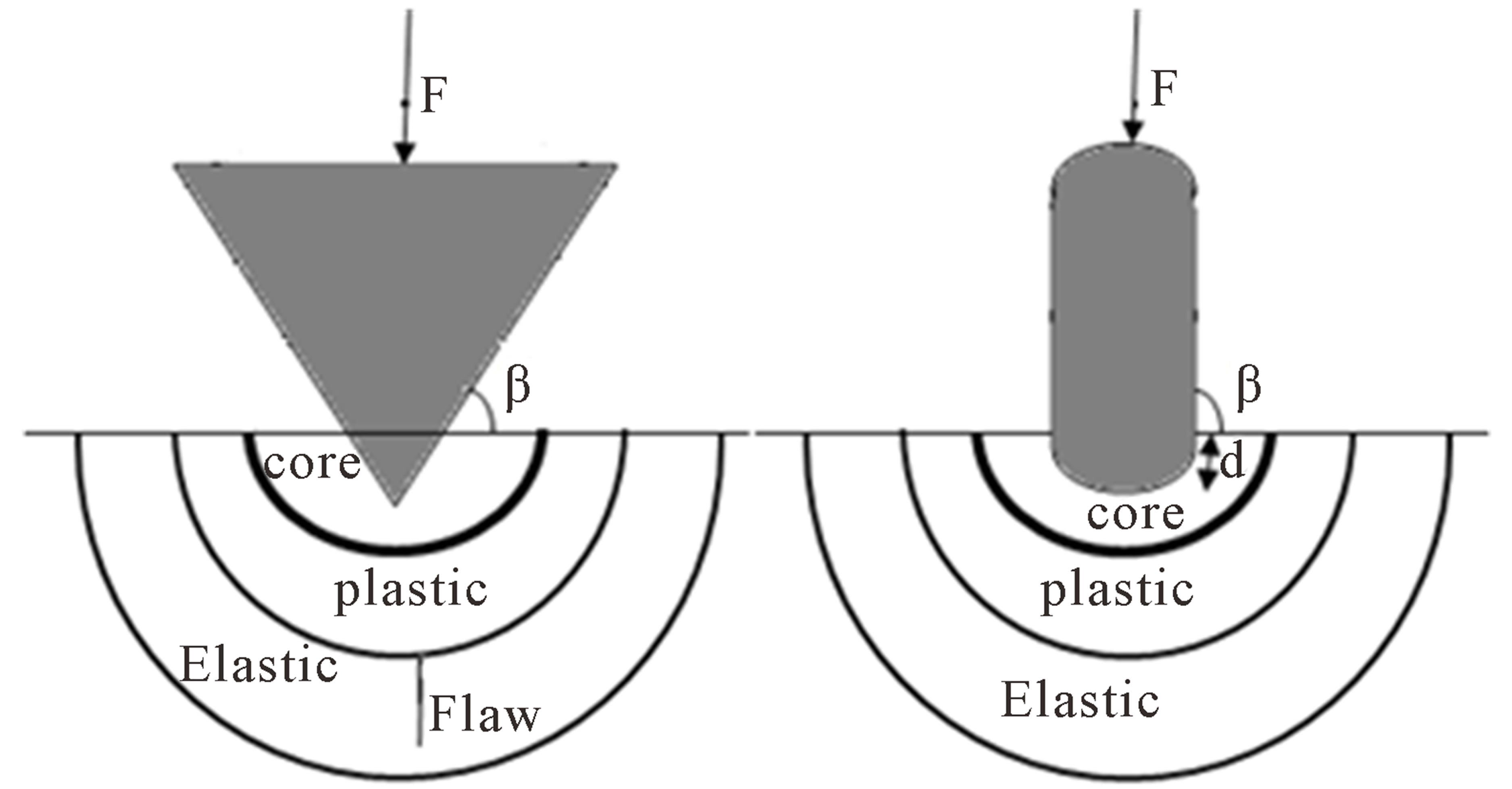
One of the complex issues in the field of rock engineering is the rock cutting and the rock indentation processes. In the mechanical rock breakage, the cutting tool is intruded into the rock to generate large and small fragments and internal cracks. The process is characterized as a rock indentation process [1,2]. Indenters may be divided into two general categories: sharp indenters (e.g. a cone or pyramid) and blunt indenters (e.g. a sphere) as shown in Figure 1.
Study on rock fragmentation by these two indenters can be found in the experimental and analytical works of some researchers [1-6]. In some of these studies the attempt was to apply different mechanisms such as Hertzian contact mechanics or cavity expansion model to the indentation of rocks with moderate thrust forces and to investigate the limits of these methodologies.
Blunt indenters were widely used in disc cutters and some other excavation machines using chisel picks (Fig ure 2). Howarth and Roxborough have studied the application of blunt indenters in the form of disc cutters using as cutting tools for Tunnel Boring Machines (TBM). They experimentally investigated the effect of penetration depth, joint width and disc edge angle on the thrust force and the specific energy (SE) may be required for
 (a) (b)
Figure 1. Indentation phenomena. (a) sharp indenter. (b) blunt indenter.

Figure 2. Blunt indenters used in disc cutter in hard rock excavation.
the disc cutters to indent into the hard rocks [7].
The main numerical methods such as finite element method (FEM), boundary element method (BEM) and the discrete element method (DEM) coupled with rock fracture mechanics can be used to simulate cracks and fractures under rock indenters. The beginning of the numerical analysis in simulation of crack in rock can be traced back to the investigations performed by Cundall in (1971) [8]. Using the finite element method to investigate the initiation and propagation of crack and rock fragmentation by indentation tools can be found, for example, in the works of these researchers [9-13].
If there is discontinuity or joint in the environment, discrete element method (DEM) is often used for modeling the cracks. Results showed that discontinuum-based DEM has the potential in simulating rock indentation and fragmentation by TBM cutters when rock joints are taken into consideration [14]. The use of boundary element method for analysis and simulation of cracks can be traced in some studies [15-21]. Displacement discontinuity method is an indirect boundary element method which has been used for the analysis of crack problems. One of the studies which were carried out on the simulation of cracks under indenters was done by Tan et al. [2]. In that study the rock properties, loading force and tool characteristics were investigated and maximum energy release rate (G) was utilized to identify crack propagation. Their findings of the study showed that chips are formed by multiple mechanisms of either tension or shear, or their combinations.
The crack propagation mechanism beneath the blunt indenters is a complex phenomenon which can usually be studied in more detail by using a modern numerical method such as the displacement discontinuity method. In this paper, a modified displacement discontinuity method using higher order displacement discontinuity elements (quadratic elements) and implementing a special crack tip element for each crack tip has been used to compute the Mode I and Mode II stress intensity factors (kI and kII) near the crack tips and then investigate the crack propagation possibility and estimates the direction of its propagation path under the blunt indenters during a rock indentation process. Therefore, in this paper initiation and propagation of crack under the indentation of blunt indenter is simulated with higher order displacement discontinuity element, to investigate the stress distribution in and around crack tip zone and also to determine the critical conditions relative to crack propagation under indenter. Singularity is an inevitable problem in crack issues, this problem has been solved using special crack tip element concept. In this analysis based on the linear elastic fracture mechanics (LEFM) principles, both Mode I and Mode II stress intensity factors are computed. Also to investigate accuracy and confidence of the carried out numerical method, the well known center slant crack problem is solved and the computed results are compared with the results given in the literature. The numerical results obtained here are in good agreement with those cited in the literature.
2. Higher Order Displacement Discontinuity Method
As it was mentioned before displacement discontinuity method is one of the indirect boundary element methods which calculates the stresses and displacements for each elements along the boundary in terms of displacement discontinuity. If distribution of displacement discontinuity along the length of an element is not constant and changes in linear, quadratic or cubic form then it is called a higher order element which has been used to calculate displacement discontinuities along that element [18,19]. Figure 3 shows the displacement discontinuity along the elements and also the positive direction of displacements discontinuity for each element along the length of it.
3. Analysis of Fracture Mechanics Issues and Crack Propagation
When numerical methods are used to analyze fracture of rock, alongside the writing equations of system, there are two main issues including the evaluation of stress intensity factor (SIF) and simulated the propagation of cracks based on the determine failure modes and different frac-

Figure 3. Displacement discontinuity element and the distribution of û(ε) [18].
ture criteria. Any of these criteria can be used alone or mixed in the displacement discontinuity method.
Stress intensity factor is based on the behavior of crack tip and uniquely governs the crack tip stress and displacement fields and represents the magnitude or strength of stress intensity of a crack tip. For a cracked body under a certain type and magnitude of loading, stress intensity factor, k, is known and the stresses and displacements and stresses can accordingly be determined. Critical value of stress intensity factor (Kc) can be easily obtained through laboratory tests of samples. Crack initiation will take place if the stress intensity factor (K) reaches its critical value (Kc). There is a common feature amongst the fracture criteria in that they all try to predict the initiation and direction of crack initial extension under mixed mode I-II loading. From the viewpoint of practical application, the three fundamental fracture criteria i.e. maximum tangential stress (σ), maximum energy release rate (G) and minimum strain energy density (S) appear to be the most commonly employed [22]. In most crack analysis in rock fracture mechanics and solid fracture mechanics maximum tangential stress (σ) is used because of the simplicity of this criteria and also due to the fact that it is a good match with brittle material. Therefore, in this modeling, we use this criterion. In this paper, the program TDDQCR1 is used for the numerical solution of plane infinite problems using the quadratic higher order elements. At first simple problems such as center slant cracks in an infinite plane is solved numerically. The results of TDDQCR are compared with the results of analytical solution to confirm the accuracy and precision of using higher order elements, particularly quadratic elements.
4. Center Slant Cracks in an Infinite Plane
Slant crack in an infinite plane is shown in Figure 4. The slant angle β changes from the y-axis, and the tensile stress σ = 10 MPa acts parallel to the y-axis. Assuming, Elasticity modulus E = 10 GPa; Poisson coefficient ν = 0.2; fracture toughness, KIc = 1.8 MPa-m0.5; and a half crack length b = 2 m.
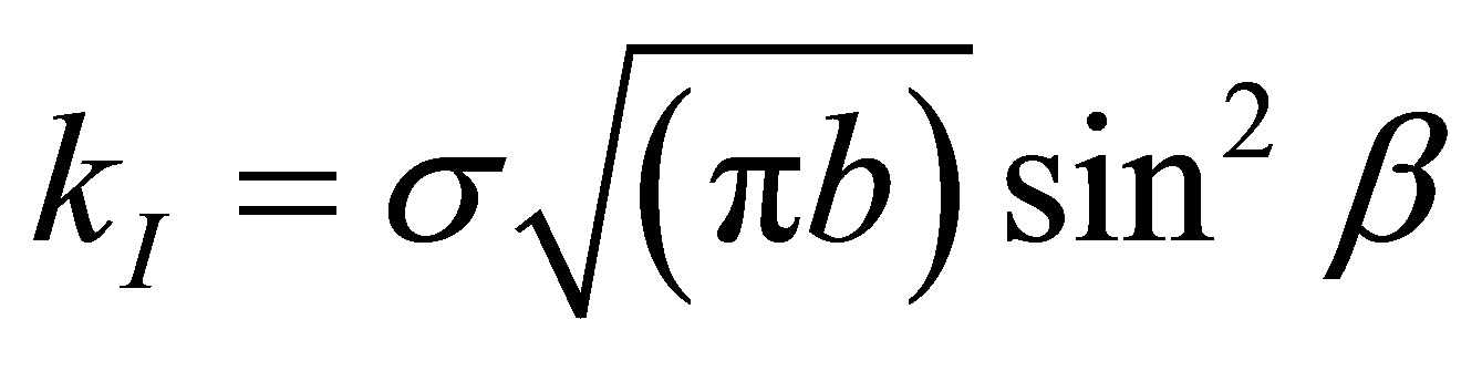
The analytical solutions for calculating stress intensity factors, for the infinite body problems are summarized in the Equations (1) and (2).
 (1)
(1)
 (2)
(2)
These equations indicate (kI) and (kII) which are functions of β. The results of Table 1 are drawn and shown in Figures 5 and 6.

Figure 4. Slant crack in an infinite plane under tension.
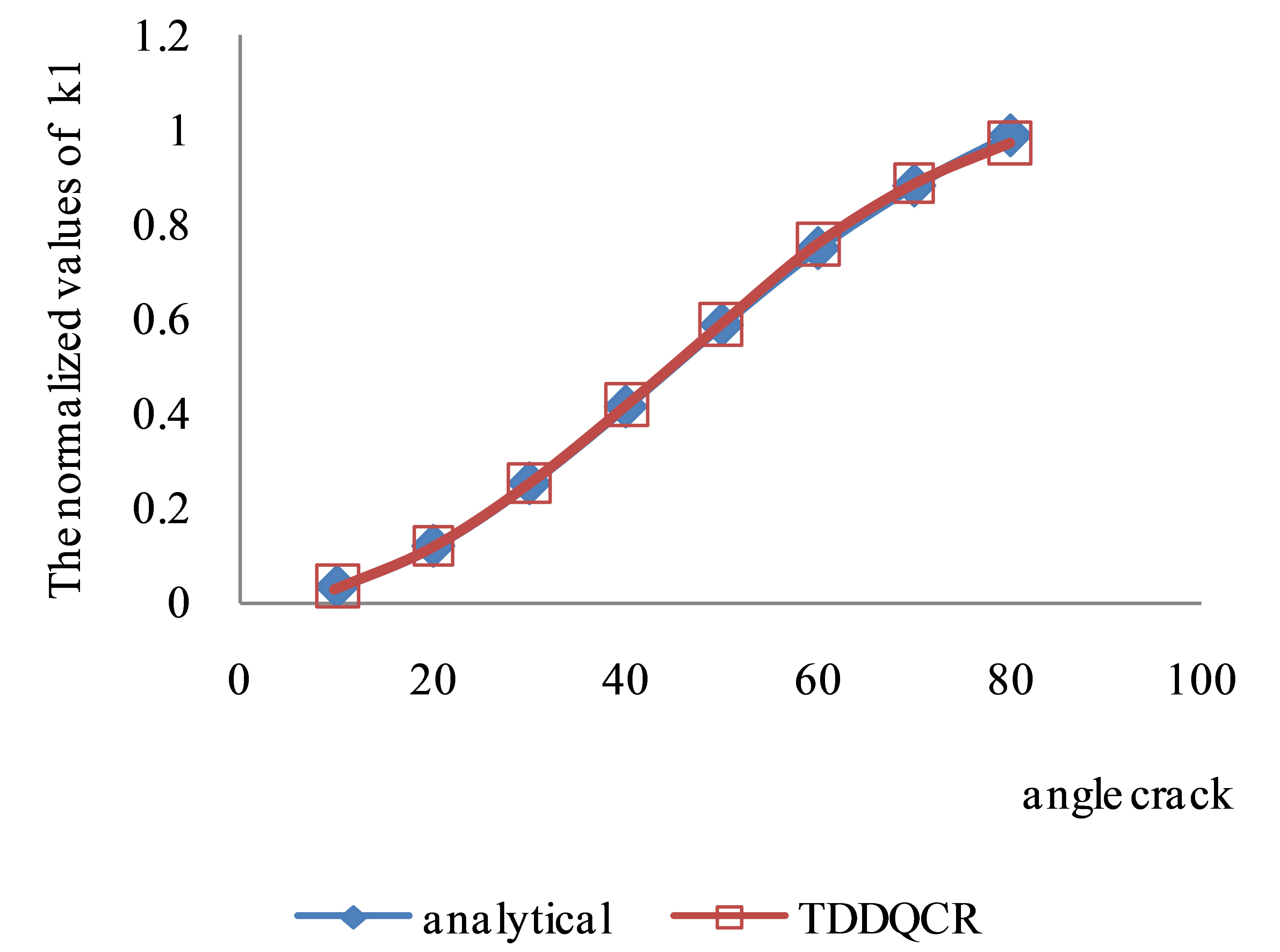
Figure 5. The normalized values of kI for the cente crack, using different β.
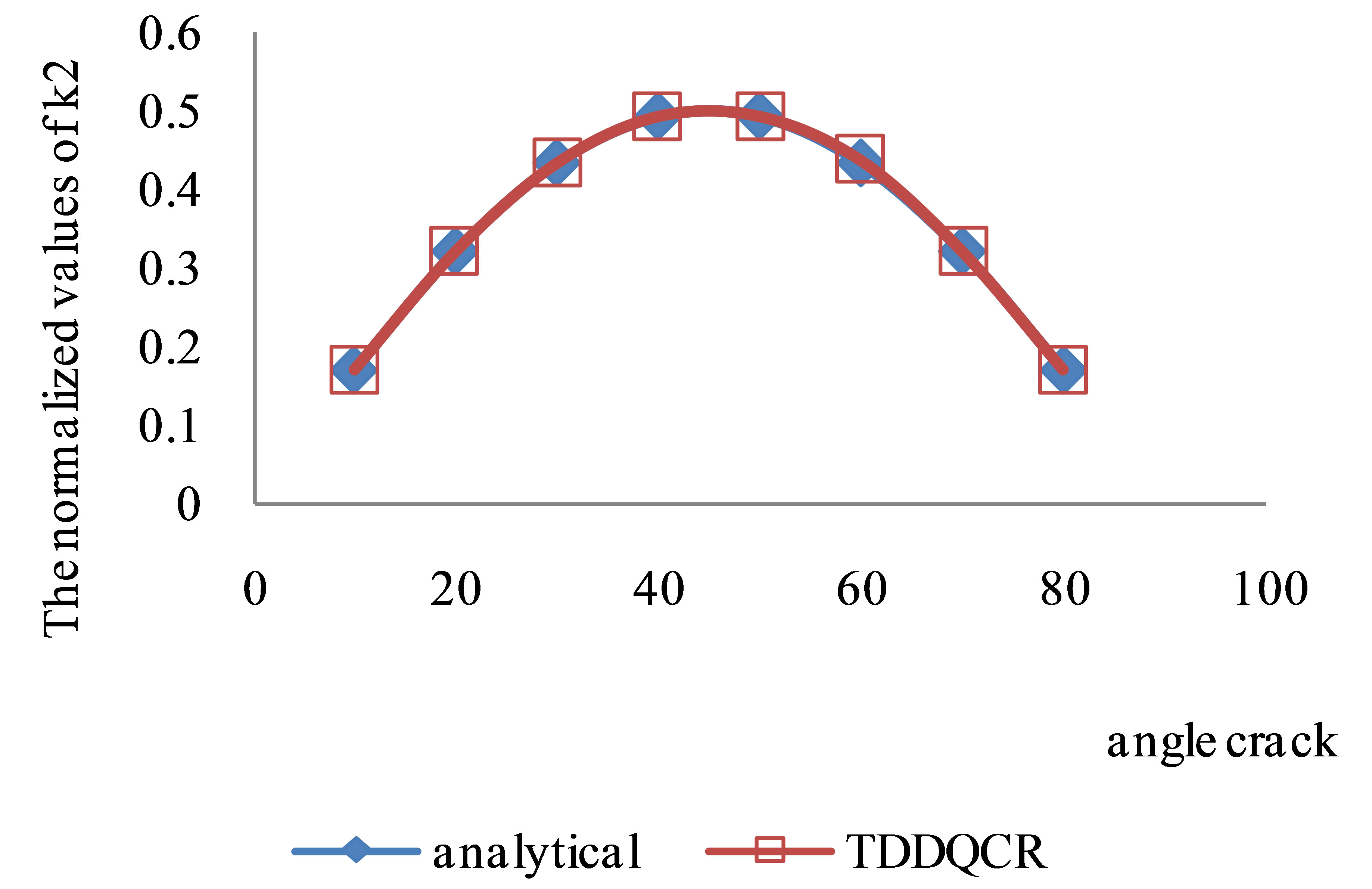
Figure 6. The normalized values of kII for the center crack, using different β.
The number of elements of crack length are 32 and 2 special crack tip elements are used. The ratio of crack tip length to crack length is considered as
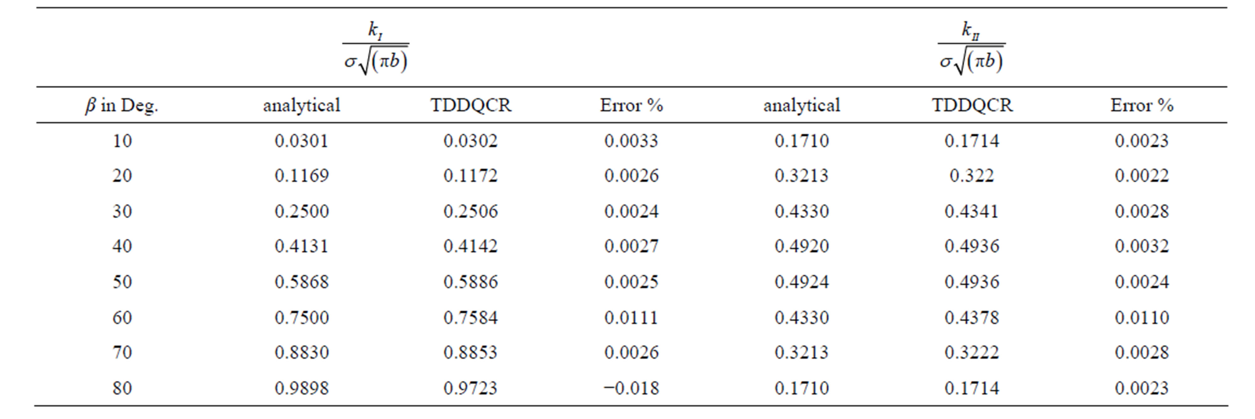
Table 1. The analytical and numerical values of Mode I and II stress intensity factors 

The computed numerical results are ccompared with analytical results and given in Table 1. Figures 5 and 6 are also drawn based on the results presented in Table 1.
Figures 5 and 6 demonstrate the accuracy and effectiveness of the proposed method. The numerical results presented in Table 1 and Figures 5 and 6 demonstrate that this computer code (TDDQCR) may be effectively used to investigate the crack propagation mechanism of slant edge cracks which may be produced during the indentation process of a blunt rock indenter.
5. Crack Propagation under Indentation of Blunt Indenter with Symmetrical Slant Crack
For simulating the crack propagation process due to indentation of a blunt rock indenter while acting on the surface of a rock mass, one may assume a square elastic plate, with certain dimensions under plane strain condition containing a semi-circular loaded area with two symmetrical slant edge cracks each of length b as shown in Figure 7. This plate contains two equal sized cracks on both of the sides of indenter. Assuming a compressive force (σ = −1 MPa) is acting to the plate and the elastic modulus and Passion’s ratio are E = 10 GPa and ν = 0.1, respectively. Blunt indenter radius is assumed to be, R = 10 cm. And the critical value of stress intensity factor (rock fracture toughness) is taken as

The crack angle (β) changes in the clockwise direction from the horizontal axis (x). Taking the advantage of symmetry in this problem, symmetry of y-axis is established, so that the only part shown in dark colors in Figure 7 is numerically solved by TDDQCR.
The symmetry boundary condition is as follows:

This program is solved for different crack angles toward the free surface (β). The ratio of tip crack length to crack length is considered

and the ratio of crack length to blunt radius

Results of TDDQCR program have been shown in the related table and figure. Negative assign (kI) shows closing of cracks, if the positive and negative (kII), assigns only show the orientation of relative cutting between the two levels of cracks.
Effects of Different Crack Initiation Angles on the Stress Intensity Factors
For investigating the effect of different angles on the value of stress intensity factors, each free surfaces boundary are divided into 20 elements, 10 elements is considered along the crack and blunt indenter is divided to 10 elements. One special crack tip is used. Table 2 shows the obtained values for the normalized stress intensity factors, and (kII) for different crack angles. the Table 2 and consequently Figure 8 shows that at low angles, More cracks propagate under tension and with increasing crack angle, crack by passing through the tension zone, enter to the pressure zone, that in this zone
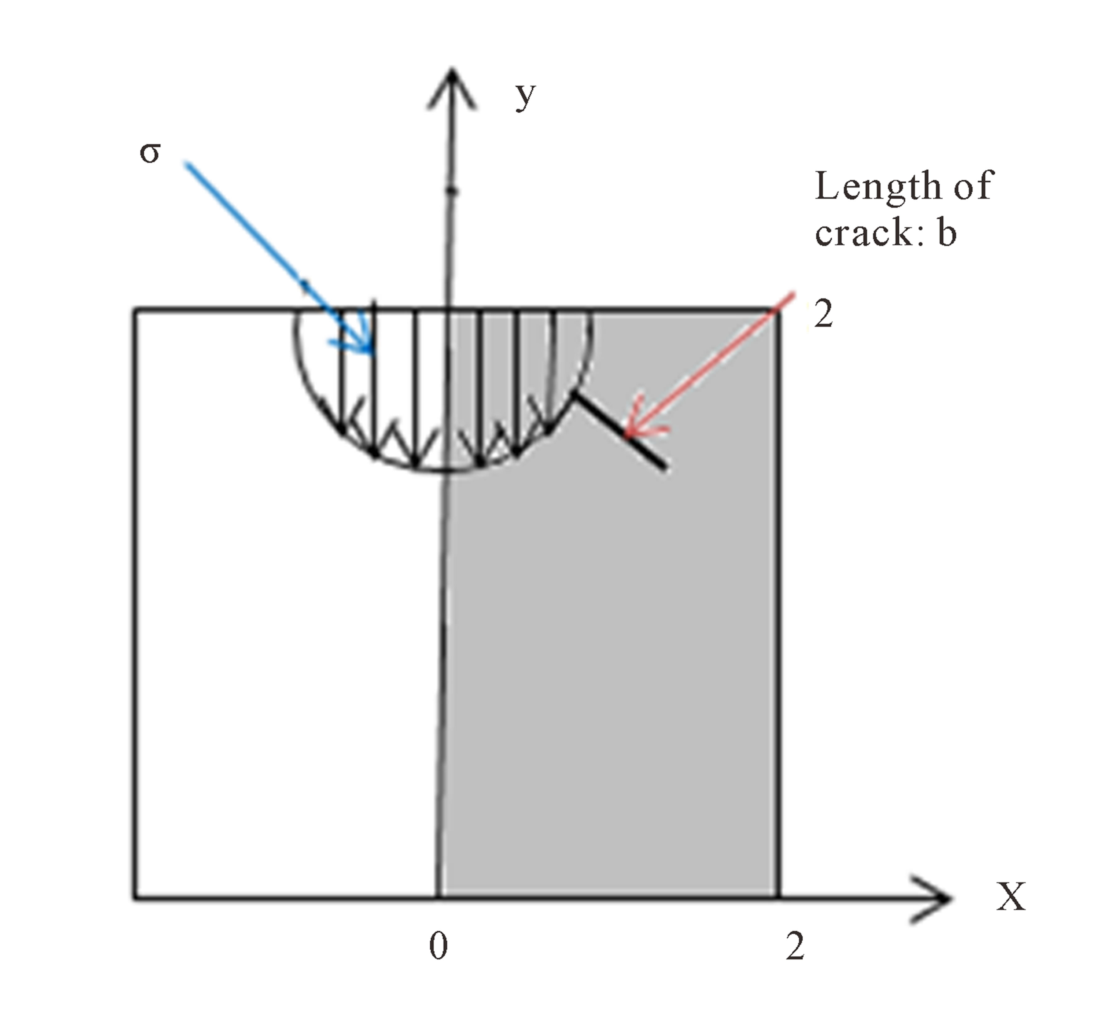
Figure 7. Assumed elastic plate with symmetrical slant crack.
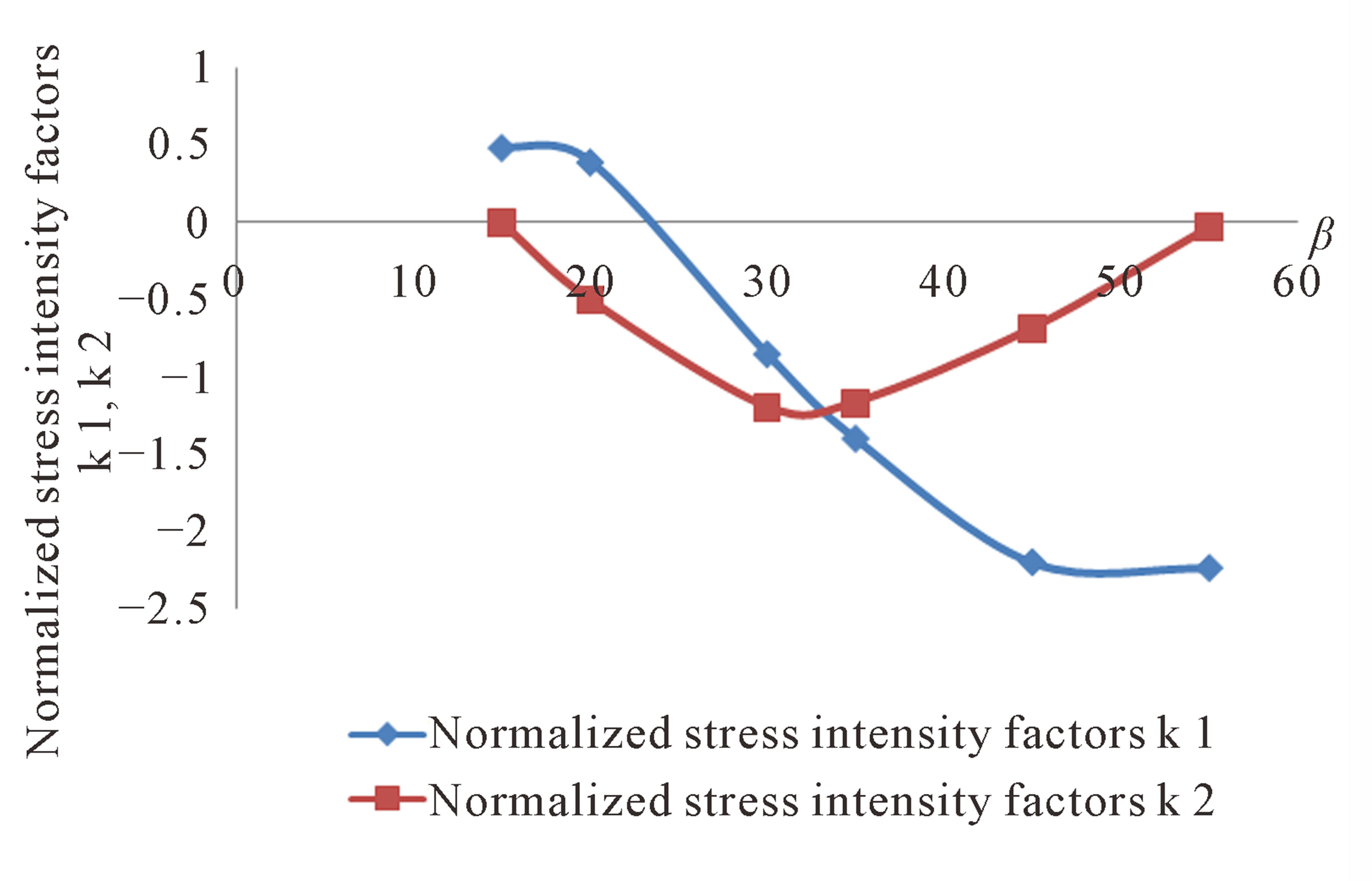
Figure 8. Normalized stress intensity factors with different angles of crack  (consequent from Table 2).
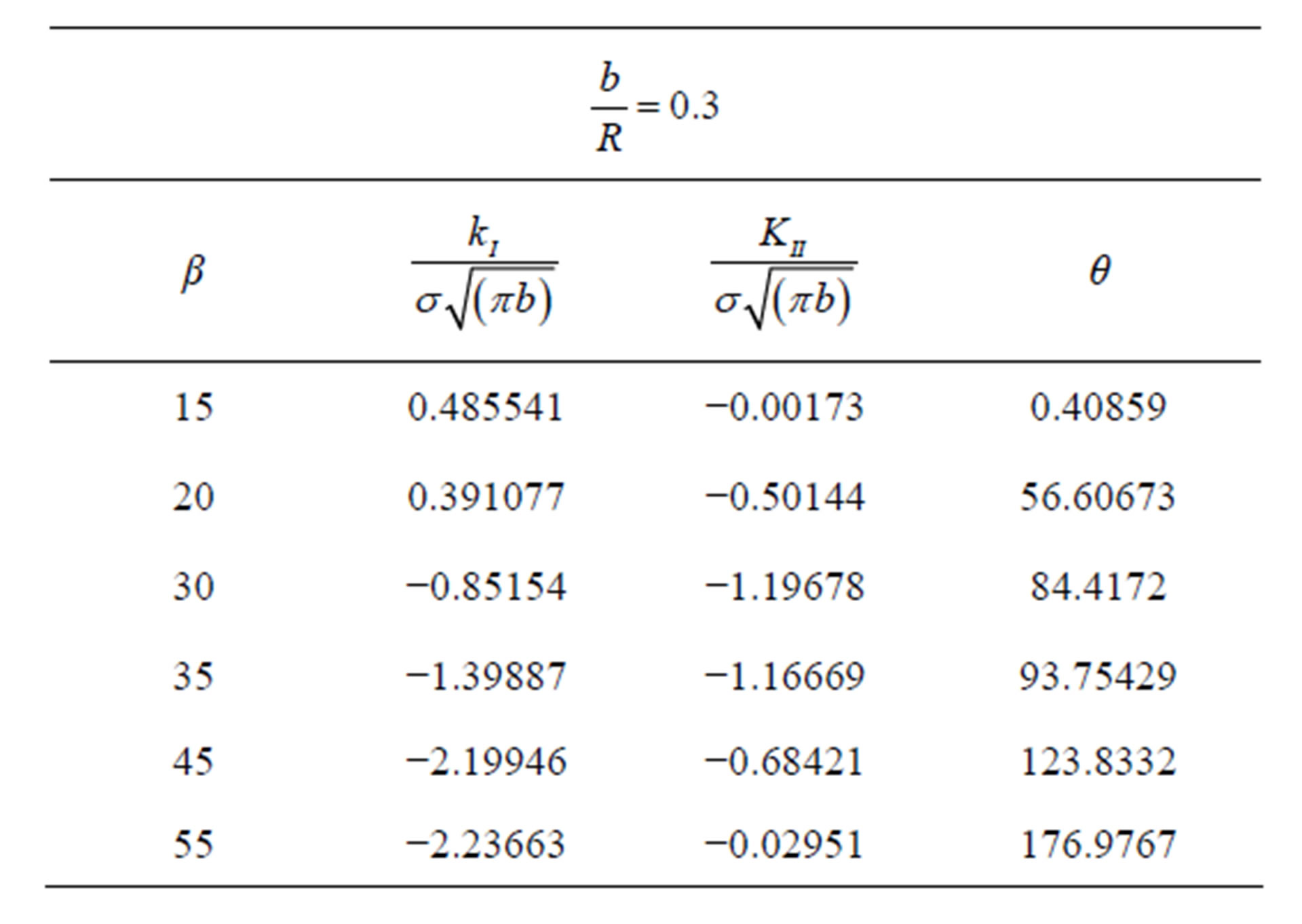
Table 2. The value of normalized stress intensity factors with different angles of crack 
closing of crack occurs and the (kI) is be negative.
As well as Figure 8 shows the value of

reduces at first and then increases and finally returns to the surface again, which means that the cracks with a low angle can propagate to the half-plate surface and so the cracks with a greater angle and nearly vertical, the effect of (kII) in fracture of rock is more further than (kI). Extension angle of crack (θ) increases with the increase of initiation crack angle (β).
6. Conclusion
Mechanism of crack propagation under blunt indenter, assuming plane-strain and quasi-static loading condition, has been numerically analyzed by applying the displacement discontinuity method (DDM) with high-order (quadratic) elements and based on the linear elastic fracture mechanics (LEFM) principles. A simple example i.e. the center slant crack was solved with TDDQCR to clarify the accuracy and effectiveness of the proposed boundary element method for solving the rock fracture mechanics problems. Ratio of crack length to radius blunt

was chosen to investigate the effect of the different angle of crack and the results showed at the low angles, more cracks propagate under tension. It is concluded that with increasing crack angle, the value of normalized stress intensity factor (kI) decreases due to moving away from applied force and another reason of the reduction of (kI) is that with increasing the angle of crack, crack may need more energy to extend and reach to the surface so that the final chipping of the rock may occur. Therefore, it may be concluded that the low angle slant edge cracks with higher value of stress intensity factors are more eligible to be produced under the blunt indenters and they may propagate towards the free surface and the crack propagation path will also be at a low angle with respect to the crack tip and again towards the free surface.
NOTES