Camber Angle Control Method Corresponding to the Electric Vehicle Age ()
1. Introduction
Since the proposal of four-wheel steering (4WS), vehicle motion performance technology has focused on improving the lateral, longitudinal, and vertical movements of vehicles by controlling chassis components, such as the steering, brakes, powertrain, and suspension. 4WS is relatively simple to describe using mathematical control models, making this topic an often investigated topic for the application of advanced control rules and leading to the development of various control algorithms for improving vehicle performance. At small lateral accelerations, the tire slip angle can be effectively controlled by steering. However, steering becomes less effective as lateral turning acceleration increases, because the tire sideslip angle also increases, resulting in a saturated tire side force. In order to counteract this weakness in 4WS, [1] -[5] suggested a method based on yaw moment control that uses the difference in the braking and driving forces between the right and left tires. This method, which has been successfully applied in practice, reduces the behavioral changes during acceleration and deceleration in the vicinity of the lateral turning acceleration limit. In order to attain maximum improvement for the kinematic performance of a vehicle in the critical limit driving state, the lateral force and front to back force of the tires must be sufficiently and effectively utilized. However, at the full skid limit, no matter how much braking force or driving force is applied, there will not be a surplus in the front to back force of the tires, and the effect of improving performance will be reduced.
On the other hand, in recent years, the conversion of vehicles to electric power has been accelerating, and if a full conversion to electric power is achieved, further advancements in vehicle kinematic control technology are expected. When vehicles are converted to electric power, in-wheel motors located in each of the four wheels will be used for braking and driving, and independent control of braking and driving at each of the four wheels will be possible. In addition, it will also be easier to independently control the steering angle of all the wheels using electromagnetic actuators. For these reasons, much research is being conducted on direct yaw moment control and active steering of electric vehicles [6] -[8] . Therefore, it is thought that kinematic performance in the critical cornering range could be further improved by significantly controlling not only the steering angle but also the camber angle of the tires through electromagnetic actuators. If the camber angle of the tires is actively controlled through actuators in accordance with the steering angle, it is possible that kinematic performance during a turning motion can be further improved. This research clarified the effectiveness in the critical cornering range of ground negative camber angle control that is proportional to the steering angle. An improvement in kinematic performance in the critical cornering range by implementing ground negative camber angle control that is proportional to the steering angle for the camber angle was clarified and is thus reported.
2. Evaluation of a Moment Method for Improving Vehicle Motion Performance
2.1. Notation
The following notation is used in the present study:
 : Distance between the center of gravity and the front or rear wheels
 : Front-wheel side force
 : Rear-wheel side force
 : Self-aligning torque of each wheel Will become apparent from the moment method the effects of ground negative camber angle control. The vehicle equation of motion cannot be solved analytically when the tire characteristics are nonlinear. Therefore, we assumed that the vehicle (Figure 1) drives straight ahead with lateral motion at the center of gravity and that yaw motion is constrained. Using the restoring moment acting on the vehicle body
 , we then evaluated the motion characteristics of the vehicle. The sum of the side forces at the four wheels is given by Equation (2).
 (1)
(1)
 (2)
(2)
The relationship between Equations (3) and (4) is shown in Figure 1.
 (3)
(3)
 (4)
(4)
A  -yaw moment diagram is constructed by calculating the restoring moment
  from the sideslip angle
  at the center of gravity and the front-wheel steer angle
 , under the constraint conditions of Figure 1. Since all of the motion states of the vehicle can be expressed as combinations of the front and rear sideslip angles, denoted as
  and
and , respectively (as calculated by Equations (3) and (4)),
  moment diagram
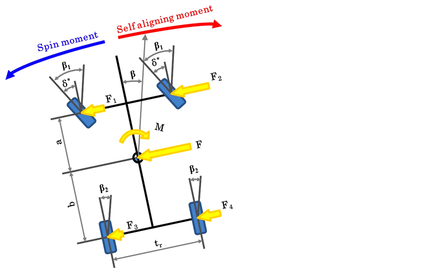
Figure 1. Vehicle model and analysis condition.
can express all states of the vehicle motion: linear, nonlinear, steady, and transient.To determine this relationship with respect to lateral acceleration,  is divided by the vehicle weight, and when the gravitational unit acceleration is taken as
 , and the relationship between
  and
and  is examined. Then, the
  line graph is obtained [9] .
2.2. Nonlinear Tire Model
The tire model uses the magic formula [10] , which is a formula that stably determines the friction-dependent tire characteristics curve. The side force  in the magic formula is computed from Equation (5), where α is the tire sideslip angle,
  is the camber angle, and
  is the wheel load.
The side force  of the tire model is determined by the magic formula coefficients
 , and
, and , as well as the parameters expressing the state of the tire, namely, the wheel load, the tire sideslip angle, and the camber angle. Table 1 shows the meaning of the Magic Formula coefficient. The magic formula parameters
  through
 , which are determined from the measurement data, express the differences in the tire characteristic curve. Because significant changes in the camber angle are brought by the actuator, tires having a round shape for the ground contact area such as with motorcycle tires are assumed. The characteristics that occur when the camber angle of the tires is changed significantly are shown in Figure 2.
 (5)
(5)
 (6)
(6)
 (7)
(7)
 (8)
(8)
 (9)
(9)
 (10)
(10)
 (11)
(11)
 (12)
(12)
 (13)
(13)
Are shown in Table 2 lower case parameters used.
2.3. Model for the Analysis of Load Distribution
Notation used in the displacement analysis model
 : Vehicle weight
 : Wheel load
 : Roll rigidity of the front and rear wheels
 : Distribution of roll rigidity between the front and rear wheels
 : Roll center height of the front and rear wheels
 : Height of the center of gravity
 : Distance between the center of gravity and roll axis
 : Front and rear wheel treads
 : Front and rear wheel loads
 : Lateral and longitudinal acceleration (in units of gravitational acceleration g)
To this end, we adopt the quasi-stable state approach proposed by Abe (Figure 3). Equations (14) through (17) describe the load dynamics of the four wheels,  through
 , during turning. (Here, we ignore the longitudinal and lateral movements of the center of gravity produced by the sine component of the roll and pitch angles). Figure 4 shows the load shifting characteristics for the lateral acceleration of the inner and outer wheels.

Table 1. Magic-Formula coefficient.

Figure 2. Tire side force characteristics (Camber angle change).
Table 2. Parameters used in calculation.

Figure 3. Model for the analysis of load distribution [11] .

Figure 4. Tire load vs. lateral acceleration.
 (14)
(14)
 (15)
(15)
 (16)
(16)
 (17)
(17)
 (18)
(18)
 (19)
(19)
 (20)
(20)
3. Effect of Camber Angle Control in the Limit Zone
3.1. Calculation Conditions
Numerical computations were performed using the parameters listed in Table3 Typical specifications for the vehicle weight ( ), wheelbase (
 ), and weight distribution between the front and rear (60:40) are assumed in the model. For suspension characteristic, it is omitted to clarify the effect of independent relative camber angle.
3.2. Effect of Camber Angle Control in the Limit Zone and Calculation Results
Figure 5 shows the vehicle motion characteristics at zero camber angle. In Figure 5(a), the vehicle drives steadily circle turning when the yaw moment is zero. When the curve is above this horizontal axis, a restoring moment acts in the direction that reduces the sideslip angle, thus stabilizing the motion. Conversely, if the curve is below the horizontal axis, the moment acts to increase the sideslip angle, thereby facilitating the turn. When the sideslip angle exceeds the limit of steady circle turning, a restoring moment is generated, and steady circle turning is no longer sustainable, causing the front wheels to reach the limit before the rear wheels, and the vehicle exists in a blow condition. Figure 5(b) shows how this action depends on the lateral acceleration. The restoring moment is generated when the lateral acceleration exceeds the lateral acceleration limit for steady circle turning.
Figure 6-8 show the results of large changes in the tire camber angle. Negative camber angles indicate that the camber angle is tilted in the turning direction. Conversely, when the camber angle is positive, the camber angle is tilted opposite the turning direction. In Figure 6, the camber angles of the front and rear wheels are Negative camber angles 20˚ and positive camber angle 20˚, respectively. When the slip angle is approximately 4˚, the specified camber angles generate a transient turning-in moment of 5 kN·m (Figure 6(a)). Hence, we infer that control of the camber angle provides effective steering in the limit zone. In terms of the lateral acceleration
Table 3 . Parameters used in calculation.
 (a)
(a) (b)
(b)
Figure 5. Yaw moment diagram (zero camber angle). (a) β-yaw moment diagram; (b) YG-yaw moment diagram.
 (a)
(a) (b)
(b)
Figure 6. Yaw moment diagram (front wheel negative camber angle 20 deg. Rear wheel positive camber angle 20 deg). (a) β-yaw moment diagram; (b) YG-yaw moment diagram.
 (a)
(a) (b)
(b)
Figure 7. Yaw moment diagram (front wheel positive camber angle 20 deg. Rear wheel negative camber angle 20 deg). (a) β-yaw moment diagram; (b) YG-yaw moment diagram.
 (a)
(a) (b)
(b)
Figure 8. Yaw moment diagram (front wheel negative camber angle 20 deg. Rear wheel negative camber angle 20 deg). (a) β-yaw moment diagram; (b) YG-yaw moment diagram.
(Figure 6(b)), the transient turning-in moment is generated at approximately 0.8 g, which is equal to the turning critical lateral acceleration under no control. This indicates that steering is effective even at the cornering limit.
In Figure 7, the camber angles of the front and rear wheels are positive camber angle 20˚ and Negative camber angles 20˚, respectively. A change in the camber angle generates a restoring moment at the cornering limit. Spinning can be prevented by supplying a transient restoring moment in this manner.
Figure 8 shows the calculation results when a front wheel negative camber angle of 20˚ and a rear wheel negative camber angle of 20˚ are applied. Compared to Figure 5(a) and Figure 8(a). It is an increase in body slip angle limit at which steady circular turning can be maintained by camber angle control. And, comparison of Figure 5(b) and Figure 8(b) reveals that the negative camber angle improves the critical lateral acceleration of steady circle turning. Providing a negative camber angle most likely improves critical lateral acceleration by 20%.
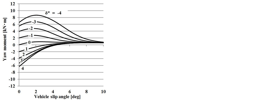
Figure 9 shows the effect of controlling the camber angle when the front-wheel steer angle δ* is 0. By changing the balance between the frontand rear-wheel camber angles, the yaw moment is changed from the turn-in side to the restoring side at the cornering limit. In the case of moment control through steering, the cornering force reaches a saturated state at the critical cornering range, and therefore, yaw moment cannot be generated. However, in the case of camber angle control, yaw moment can be generated without becoming narrow even in the critical cornering range.
4. Simulation Using a Vehicle Model
4.1. Notation
The following notation is used in the present study:
 : Vehicle total mass, Spring mass {1600, 1387 kg}
 : Yaw, Roll moment inertia {
 }
}
 : Wheelbase, Distance between the center of gravity and the front or rear wheels {2.6, 1.02, 1.58 m}
 : Front and rear wheel treads {1.47, 1.459 m}
 : Pneumatic trail of front or rear wheels {0.03, 0.03 m}
 : Lateral acceleration
 : Vehicle body sideslip angle, Vehicle forward speed
 : Sideslip angle of front and rear wheel
 : Camber angle of front and rear wheel
 : Yaw rate, Roll angle of vehicle
 : Front-wheel steer angle
 : Distance from vehicle CG to roll axle {0.52 m}
 : Roll center height of the front and rear wheels {0.046, 0.05 m}
 : Front roll stiffness, Rear roll stiffness {47,040, 50,960 N∙m/rad}
 : Total roll stiffness
 : Roll damping coefficient {4000 N∙ms/rad}
 : The front and rear wheels camber stiffness by lateral force
 : Camber angle change of front and rear wheels roll angle per unit
 : Side force of each wheel, wheel load
( is inner or outer wheels.
  is front or rear wheel)
 : Acceleration of gravity
4.2. Computation Model
The vehicle model for analysis was a model having three degrees of freedom (yaw rate, body slip angle, and roll). Moreover, it was assumed that the suspension characteristics were linear, and that the slip angle and camber angle of the tires were the same for the right and left tires. The equation of motion is expressed by the following Equation (21) [12] .
 (21a)
(21a)
 (21b)
(21b)
 (21c)
(21c)
for the tire slip angle:
 (22)
(22)
for the tire camber angle:
 (23)
(23)
where
 (24)
(24)
It uses a Magic-Formula tire model shown in Section 2.2 as a model for cornering characteristics of the tire, and using the same tire characteristic.
In addition, when the  the front and rear left and right wheel load movement amount
 (25)
(25)
wheel load of each
 (26)
(26)
4.3. Calculation Conditions
Input a step steering with a front wheel actual steering angle of 4˚ while traveling at a vehicle speed of 95 km/h. For camber angle control, implement front and rear wheel ground negative camber angle control (20˚) simultaneously with the steering angle.
4.4. Computation Results
Figure 10 show the results of simulation. When camber angle control is not implemented, after step steering is input, the values for the body slip angle and lateral acceleration when the vehicle has settled into a steady state are nearly the same as the threshold limit value at which a steady circular turn can be maintained through moment method analysis. From this, it is evident that the cornering limit is simulated. When ground negative camber angle control that is proportional to the steering angle is implemented, convergence of the yaw rate and body slip angle is improved compared to when it is not implemented, and the vehicle swiftly settles into a steady state. From the lateral acceleration calculation results, when control was not added, the lateral acceleration limit at the steady state was 0.8 g. In contrast, when ground negative camber angle control that is proportional to the steering angle was implemented, the value thereof improved to 0.9 g. Thus, cornering limit performance is significantly improved through ground negative camber angle control that is proportional to the steering angle.
5. Experiment Using a Model Car for Camber Angle Control Associated with the Steering Angle
We verified the computation results through the following experiment using a model car. Using a remotely controlled model car, we clarified the effectiveness of four-wheel negative camber control proportional to steering.
5.1. Model Vehicle
The model car used in the experiment is shown in Figure 11, and its dimensions are listed in Table4 We used a 7.2 V battery intended for use in model cars, and moved the model car using wireless LAN communication. The toe angle and camber angle could be controlled with the motor. Embedded measurement equipment in the model enabled us to measure the lateral acceleration and yaw rate. We evaluated camber angle control associated with the steering angle in an experiment in which the vehicle traveled in circle.
5.2. Method Used to Achieve Camber Angle Control
In order to achieve four-wheel negative camber control proportional to steering in the model car, we controlled the camber angle by moving the link mechanism using the servo motors on each of the tires. The camber angle,
Table 4. Specifications of the model vehicle.
 , of the model car was set to be proportional to the steering angle with a camber angle gear ratio of
 , as opposed to the handling angle under regular steering,
 .
.
 (27)
(27)
5.3. Experimental Conditions
The model car experiment was performed with the vehicle driving in a circle, as shown in Figure 12. The experiment was conducted under conditions with and without negative camber angle control. The speed of the model car in the experiment was set at its potential critical cruising speed under conditions with and without negative camber angle control, and was set such that the designated speed was maintained. We can therefore say that the experiment using the model car was conducted in the critical cornering range. The experiment was conducted by four subjects at random who were not informed of the experiment parameters.
5.4. Experimental Results
The representative results of the experiment in which the car ran a circular course are shown in Figure 13. We found that, where negative camber control proportional to steering (±20˚) was implemented, lateral acceleration improved by approximately 0.10 - 015 g, as compared to the case in which no control was implemented. Moreover, when camber angle control was implemented, the speed was 2.3 m/s, whereas the speed was 2.1 m/s for the case in which no camber angle control was implemented, indicating an improved potential cruising speed during cornering. The experiment results indicate that the yaw rate was higher with negative camber angle control proportional to steering than without control, because of the improved lateral acceleration achieved by negative camber control. Using a model car, this experiment confirmed that stability in the cornering margins is improved through the use of negative camber angle control proportional to steering.
6. Conclusion
This research focused on a method of ground negative camber angle control that is proportional to the steering
angle as a technique to improve maneuverability and stability to support the new era of electric vehicles, and the effectiveness thereof was clarified. As a result, it was found that camber angle control can control both the yaw moment and lateral acceleration at the turning limit in the critical cornering range as well. It was also confirmed that both stability and the steering effect in the critical cornering range are improved by implementing ground negative camber angle control that is proportional to the steering angle using actuators. Dramatic improvements in cornering limit performance can be achieved by implementing ground negative camber angle control that is proportional to the steering angle.