Design and Implementation of FFPIV Scheme for Closed Loop Motion Controller ()
1. Introduction
For many years, motion controllers have been extensively applied in industrial automation systems. A motion controller is a kernel control device in electronic and mechanical manufacturing. Classifying on communication interfaces between hosts and controllers, motion controllers fall into sub-categories such as parallel communication like PCI-bus and ISA-bus, serial ones like RS232 and Ethernet protocol. Although serial-bus-based systems have lower prices and flexibility due to popular Ethernet standard [1] [2] , these systems are not guaranteed stability and/or desired performance, especially high traffic on the bus. Conversely, parallel-bus-based applications present good performance in term of high speed and high accuracy. However, ISA-bus-based control systems meet great drawbacks: tightly bounded to host architecture which is normally old design, lack of geographical addressing to add new devices and low response speed. Hence, many works have developed the PCI-bus-based motion control systems using specific chips or general purpose microprocessors. In [3] , authors investigated a simple motion controller based on LM628 microprocessor. This controller can simplify the hardware circuit and reduce the developing costs. On the other hand, it is only suitable for medium-sizedand mini-type control systems for the few axes. Furthermore, more axis controlling can be achieved by using DSP chip as the main element of motion controller.
Various researchers focus on developing DSP-based motion control systems. Authors in [4] [5] proposed a multi-axis servo motor motion controller based on DSP. In this design, DSP chip communicates with upper computer through Dual Port RAM and receive feedback signal from servo driver. Then, this controller calculates the error between theoretical interpolation position and actual position, and operates PID algorithm to achieve target position. Besides, Komin and Tanta-ngai in [6] also presented DSP-Based motion controller system that is able to control up to eight motors at the same time. Motion controller collects G-code from PC, computes path profile and interprets to command in order to control motor drive. By using profile calculation method, the developed system provides smooth movement for various path types. Chunhao et al. in [7] introduced a simple but effective motion controller based on the industrial PC. The advantages of this system are the low price and welladapted design to integrate into packaging, printing, textile and assembling industry.
Recently, several topics of advanced control are applied in motion controller such as a modified fuzzy logic control in automotive system [8] , fuzzy PID with feed-forward control strategy in CNC machine [9] [10] , fuzzy PI/PD-based control scheme in tracking applications including disturbance rejection and external loading [11] [12] , self-tuning fuzzy PID through continuous updating approach of output scaling factor [13] , a hybrid fuzzy bang-bang controller to improve the motor behavior [14] [15] or fuzzy PID with a class of gain matrices depending on the manipulator states [16] .
The other strategic approach to enhance the performance of manufacturing machine is how to lessen the tracking error. In modern and practical environment of production, existing frictions degrade the manufacturing precision. Researchers in [17] study two friction models in machine tools namely; static friction and Generalized Maxwell-slip model. Both identified friction models can be applied in feed-forward compensation scheme to improve tracking and positioning performance of machine tools. For velocity-controlled motion system, velocity-based friction compensation structure with additional velocity input in [18] is developed to overcome the adverse effects induced by friction to an extent. The friction compensation consists of the given position commands, velocity commands and an integrated friction model. The results prove that three-axis machine can reduce significantly the absolute contouring errors during motion. Besides, the uncertainties of parameter variation and measurement problems lead to decrease the motion accuracy. In [19] , a state-space disturbance observer is successfully applied to estimate and compensate for these uncertainties. Experimental results indicate that the roundness error has been considerably reduced. For the other implementation issue, authors in [20] gave out a frequency domain based method for controller design in nonlinear system. This approach optimally designs a feed-forward friction compensator. It is suggested that in frequency domain the design yields a tool to fast and easily control the friction in practice.
In this paper, a novel DSP-based motion controller for industrial machine that implements feed-forward PIV algorithm is proposed. This controller can significantly lessen the tracking error that is the main factor of high precision machining, and reject the unknown disturbance of model. Therefore, the motion controller which consists of design of DSP and FPGA can be used in manufacturing broadly.
2. Structure of Motion Control System
The overall structure of motion control system is illustrated in Figure 1. The host IPC is Industrial PC with windows operating system. Through PCI bus, more than one industrial motion controller can communicate with host. Moreover, a motion controller can control up to 8 servo drivers simultaneously. Hence, the task of industrial motion controller is to perform arithmetic calculation operations with data from host and receive the displacement from servo driver. Additionally, this controller distributes the control value to servo motor in order to form the closed-loop control.
3. Hardware Design of Motion Controller
In the motion controller, main hardware components are displayed in Figure 2. The core of motion controller is

Figure 1. Overall structure of motion control system.

Figure 2. Hardware design of proposed motion controller.
a Digital-Signal-Processor, which is explored to use the powerful computation function. The DSP completes most of tasks such as real-time communication with PC, motion profile generator, velocity and position control of servo motor, monitoring condition of servo motor and external signal detection. In addition, this motion controller also includes Digital-Analog-Converter, Dual-Port-RAM, Synchronous-DRAM, Flash, FPGA, PCI-interface-chip and other peripheral circuits. Whilst DPRAM not only holds the communication interfaces between controller and host but also supports sufficient buffer, FPGA is responsible as address decoder. Furthermore, PCI-interface-chip is a 32-bit PCI-bus target interface chip to ensure the PCI industry standard. In order to support memory spaces, RAM and Flash are designed to store data (position, velocity, sensor signal, parameters of controller, etc.).
When the controller works, host transmits user-specified data from DPRAM to DSP to provide the initial information. In a cycle of servo, DSP achieves the feedback signals, for instance, position and speed from servo motor. Therefore, it computes the differences between hypothetical values and real values, and executes the control strategies to acquire the necessary adjustments. Then, the output results are carried on digital analogy conversion by DAC chip and amplification by amplifier circuit. Finally, the output signal will be sent to the servo driver in order to control motor.
3.1. DSP Module
In recent years, DSP is used in digital control system widely, especially in motion control system. The reasons to choose DSP as the central component are primarily in processing ability, on-chip memory, interface and other on-chip resources. It is a high performance 32-bit floating-point digital signal processor, which is appropriate for industrial control application. External working clock’s frequency can be up to 300 MHz which allows the execution of eight instructions in parallel each cycle.
3.2. FPGA Module
The design of FPGA focuses on input and output module to handle the communication in motion controller: DSP chip, D/A conversion, encoder signal and other feedback signals. It receives the data from servo driver; count a number of pulses and feedback to DSP. The interrupt is generated whenever positive/negative limit signals, home signal and alarm signal appear to be processed. The operator to combine among these signals is OR. When the rising edge of signal comes to FPGA chip, there will be a trigger signal to DSP in order to generate the interrupt service routine.
3.3. Communication Modules
The computer in early period used ISA-bus to control the motor. Nonetheless, the response speed was slow, and real-time performance was not guaranteed in those days. Since PCI-based control system was developed, motion control system had a great advantage to satisfy the requirements of industry. The local-bus clock of PCI is asynchronous with the PCI-bus clock. Whereas the PCI runs at 33 MHz with the burst transmission speed of 132 MB/s, the Local end can support the maximum clock frequency of 60MHz with the burst transfer speed of 200 MB/s. It has performance features such as two programmable FIFOs for zero wait state burst operation, supporting both multiplexed and non-multiplexed 8-, 16- or 32-bit address/data protocol.
In manufacturing machine, it is essential to provide a shared memory to access among processors in order to guarantee high-speed data transmission. As a result, Dual-Port RAMis showed high performance to complete this task, which handles the data transmission between host and DSP quickly and certainly. It has dual-ported memory cells which allow simultaneous access of the same memory location, expandable data bus to 72 bits and onchip arbitration logic.
To deal with the input of servo driver, Digital-Analog-Converter is used to convert digital control signal to analogy control signal, then, transfer it to servo driver. The design selects a quad, serial input, 12-bit DAC. The voltage output ranges from −10 V to +10 V.
4. Software Design of Motion Controller
4.1. Data Exchange
Elements of software design in this motion controller include library, firmware and windows-based application. Firmware is implemented on-board’s DSP for motion profile generator, control algorithm to follow and reach target position. It also copes with control software to communicate with peripheral device through environment variable appropriately. Library acts as the interface of firmware and system software to perform the desired functions by providing optimal command functions. Besides, the purpose of windows-based application is to support user with tuning parameters interface and receiving the feedback signal to display in graph intuitively.
As shown in Figure 3, software data flow of the communication performs between controller and system software through DPRAM. In system software of host, the library data structure gets the possibility to communicate with firmware. Consequently, firmware and RAM memory use the same data structure in the operation. Most of data in firmware reads through DPRAM. If it needs to set the data or to perform the command via li-

Figure 3. Data exchange in proposed motion controller.
brary, the corresponding data is written to DPRAM data and again copied to RAM memory for actual operation to use. When the operation completes, data in RAM memory is copied to DPRAM and feedback to system software.
4.2. Motion Algorithms
If motion controller is the key components of motion system, then control strategy is the key technology of motion controller. To drive the motor smoothly, S-curve profile generator algorithm is programmed in DSP to define the trajectory.
In Figure 4, full S-curve profile is divided in seven segments including the values of jerk, acceleration, velocity and position.
For period :
:
 (1)
(1)
 (2)
(2)
 (3)
(3)
 (4)
(4)
For period :
:
 (5)
(5)
 (6)
(6)
 (7)
(7)
 (8)
(8)
For period :
:
 (9)
(9)
 (10)
(10)
 (11)
(11)
 (12)
(12)
For period :
:
 (13)
(13)
 (14)
(14)
 (15)
(15)
 (16)
(16)
For period :
:
 (17)
(17)
 (18)
(18)
 (19)
(19)
 (20)
(20)
For period :
:
 (21)
(21)
 (22)
(22)
 (23)
(23)
 (24)
(24)
For period :
:
 (25)
(25)
 (26)
(26)
 (27)
(27)
 (28)
(28)
where ;
;  and
and ;
; ;
; ;
; 
Once, the time duration in each segment is obtained from above equations. S-curve profile drives the servo motor to target position smoothly.
In industrial actuators, nonlinear and uncertain factors often exist throughout the operation. To reach the achievement of precision motion control, a system’s nonlinearity must be eliminated. Many traditional approaches such as PID control scheme were researched. Nonetheless, conventional PID controller, adjusted using Ziegler-Nichols or trial-and-error technique, can usually meet poor performance requirements. But rising time and overshoot seem difficult to modify to be obtained the good result [21] . In order to have a better estimation of the system response, easier-tuning-topology, considerably separate overshoot and rising time, an alternative controller is needed. As a result, Proportional-Integral-Velocity control scheme is recommended. Nevertheless, with only a feedback control scheme, the tracking error due to servo lag phenomena still occurs. One of the existing solutions is to add the feed-forward controller into the main control scheme to enhance tracking performance. For this kind of design, the feed-forward control scheme is independent in case the values of parameters in the position loop controller change.
The overall control scheme of motion controller is described in Figure 5. The proposed controller includes a position loop with velocity loop. In this design, the error of position multiplied by KP becomes a velocity correction command. The term KV is used to estimate velocity of system. Later, the integral factor KI is applied directly on the velocity error. Finally, both velocity and acceleration feed-forward unit are added to greatly minimize the tracking error.
 : Gains of proportional, integral and velocity loop respectively.
 : Total inertia, damping, torque constant, disturbance torque, angular displacement of servo motor.
 : Estimated torque constant of servo motor.
 : Velocity, acceleration feed-forward gain.
Position, velocity and acceleration reference are from motion profile generator.
The output torque control is presented:
 (29)
(29)
uFF and uPIV are torque control of feed-forward and PIV control scheme correspondingly.
4.3. Control Flow
The structure of control software is designed to obtain the high performance systematically. As shown in Figure 6, the main routine of motion controller is introduced. Firstly, system control registers are initialized. Then, several sections in DPRAM store the default values such as firmware version in index section, motion coefficients in motion section, sensor status in supervisor section. At the same time, RAM memory is activated for internal variables. The setting hardware and interrupt are completed before the end process of initialization. In the next task, the program stays in a loop named as Command Manager. This sub-function will manage the whole operations of all axes in motion system continuously.
The content of Command Manager is demonstrated in Figure 7. It can be seen clearly that controller spends a lot of time in Control Loop. During this time, the controller collects sensor signals and checks error conditions of amplifier and encoder. The Control Loop also manages the supervisor command executions such as motion commands and global commands. In Channel Control, several statuses of sending or receiving channel are defined to ensure the continuous communication between host and motion controller. In the case of ready status in channel, host sends the motion command to start computing path planning.
When motion is done or meets error, the controller will send interrupt to host to notify the condition of motion system. Then, data is updated through DPRAM to demonstrate the motion parameters in window-based application.
5. Experimental Implementation
In this section, experiment is set up on DSP-based motion control system in Figure 8. The host computer is In-

Figure 5. Block diagram of proposed motion controller.
dustrial PC with Windows OS. The proposed motion controller can interface with user through Windows-based application. The AC servo motor SGMJV-02ADA21 which has an incremental encoder with a resolution of 2048 pulses/revolution is driven by servo driver SGDV-1R6A01B. All of them are produced by YASKAWA Company.
To verify the fast, smooth and accurate response of motion system, the proposed motion controller is programmed in industrial mode operations: acceleration motion, blending motion and step motion. The result data includes command and actual velocity, torque effort. All of these have the same control gains of motion controller, KP = 2.5, KI = 0.02, KV = 50 and KVFF = 30. In Figure 9, experimental performance is achieved with full S-curve motion planning strategy. The result indicates that the controller brings the actual profile to the specified profile smoothly. In blending motion test of Figure 10, a simple strategy to blend two segments together by shifting the speed segment along the time domain. Although actual velocity varies in several desired values during the process of motion, the torque is observed to be stable; hence, smoothness and accuracy are still guaranteed to obtain high performance. As shown in Figure 11, the motor closely tracks the pre-defined trajectory even
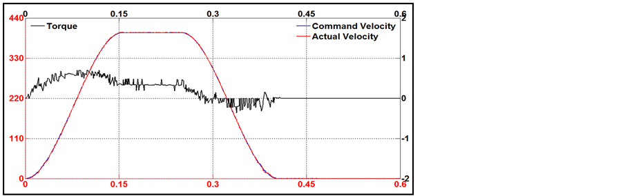
Figure 9. Performance of proposed motion controller in acceleration motion mode.

Figure 10. Performance of proposed motion controller in blending motion mode.
at short time. Clearly, the response is fast and satisfies the requirements of real-time control. Moreover, the operation of motion system is promised to be stabilized in most of executing duration.
It can be seen that the proposed motion controller has a superior performance and highly machining accuracy. Servo motor is sufficiently driven to track desired trajectory regardless of the types of motion modes. The programming implementation is based on DSP control board and C/C++ language. This environment permits most of motion control engineers to develop the extensive applications not only in the laboratory, but also in practical

Figure 11. Performance of proposed motion controller in step motion mode.
factory. In this way, it is suggested that the developed motion controller is significantly suitable for manufacturing machine.
6. Conclusion
In this paper, a feasible and effective control scheme has been proposed for closed-loop motion system. The controller implemented feed-forward PIV strategy which combines velocity/acceleration feed-forward control unit with a velocity loop. The results in experiment prove the smooth profile, highly tracking accuracy and realtime performance. Thus, this controller is suggested to be applicable in industrial precision closed-loop motion control system like CNC machine, robot control.
Funding
This Work was supported by Dong-eui University Foundation Grant (2011).