Trajectory Tracking of Quadrotor Aerial Robot Using Improved Dynamic Inversion Method ()
1. Introduction
Since the beginning of 20th century, many research efforts have been done to create effective flying machines with improved performance and capabilities. The quadrotor aerial robot is emerging as a kind of popular platform for unmanned aerial vehicle (UAV) research due to its simple structure, hovering ability and vertical take-off and landing (VTOL) capability. It is especially suitable for reconnaissance and surveillance missions in complex and tough environment. Because of quadrotor’s complexity of dynamic and uncertainty of parameters, it is usually chosen as a testbed for validating the advanced control algorithm of nonlinear control.
The quadrotor is described as aero robot in [1,2]. The core problems of quadrotor are attitude control and trajectory tracking control. The flight control unit and its control programming code are priority to its structure when treated as a testbed for control algorithm. With the emerging of open code project for autonomous control, it’s more convenient to transplant the advanced control algorithms from modeling and simulation to validating test, which also provide great help to research enthusiast or aerial robot hobbyist. In [3], the differential flat control and nonlinear inverse control are proposed to process the nonlinear trajectory control for differential flatness property system. In [4], an real-time nonlinear optimal control, which is called  technique, is employed to solve the resultant challenging problem considering the full nonlinear dynamics without gaining scheduling techniques and timescale separations, which leads to a closedform suboptimal control law. In [5,6], the back-stepping procedure is synthesized for the purposes of stabilization and trajectory tracking, which is generally robustness applied to the system of parameters uncertainty and unmodeled dynamic to some extent. The various types of aerial robot UAV based on quadrotor concept are put forward in [5-8], using the superiority of fix-wing plant and rotor-wing helicopter to enhance the VTOL ability and flying range. So, in general, the dynamic inverse method is more suitable for various types of aerial robots due to its start from original model. In [9], the dynamic inverse control with zero dynamic for non-linear affine model system is proposed. In [10], the hierarchical flight control is synthesis for rotorcraft-based UAV. In present paper, the hierarchical structure of improved dynamic inverse method for quadrotor trajectory tracking is proposed, which can balance the deviation of model inaccuracy to enhance the robustness of control system.
In this paper, we first describe the mechanism of quadrotor aerial robot in section 2. Next, we establish the dynamic model of quadrotor obtained from NewtonEuler formula in section 3. In secion 4, a hierarchical structure of improved dynamic inversion method is proposed. Furthermore, robustness with respect to parameters uncertainty and unmodeled dynamic has been observed in simulation. Finally, a trajectory tracking example is simulated and remarked.
2. Quadrotor Mechanism
The typical quadrotor mechanism and coordinate system is briefly showed in Figure 1, where four rotors are cross structure, providing the three required moments (roll, pith and yaw) and lifting force. For describing the flight condition of quadrotor exactly, we can respectively define flat-earth frame E and rigid body frame B according to right-hand rule.
The aerodynamic forces and moments of propeller depend on various parameters, such as the angle of attack, aerofoil and inflow ratio. We assumed that the aerodynamic forces  and moments
  of four propellers are proportional to the square of angular velocity
 . Which is given by:
 (1)
(1)
where . The
. The  is respectively aerodynamic force and anti-torque coefficient. Since the forces and moments are derived by modifying the speed of each rotor, then the lifting force and three moments can be given as follows:
Lifting force (the sum of four rotor forces):
 (2)
(2)
Roll torque (right-hand rule):
 (3)
(3)
Pitch torque (right –hand rule):
 (4)
(4)
Yaw torque (right –hand rule):
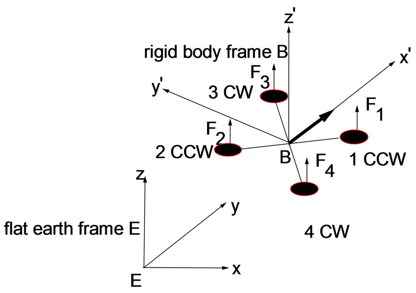
Figure 1. Quadroter UAV coordinate frame systems.
 (5)
(5)
where L is the distance from motor position to the center of quadrotor mass. Rewrite the matrix form of Equations (2)-(5) as follows:
 (6)
(6)
3. Dynamic Model of Quadrotor
The frame E stands for earth coordinate system, and the body frame B stands for the rigid quadrotor coordinate system. The body coordinate B is attached to the center of mass of the quadrotor. The Euler angles which denote the rotation of quadrotor in the flat-earth frame coordinate E is the variables ,
,  and
and ,which respecttively represents the roll, pitch and yaw angles of the quadrotor in the body-fixed coordinates.
3.1. Six DOF Model of Rigid Body
The dynamics of a rigid body under external forces applied to the center of mass expressed in the body fixed frame are in Newton-Euler formalism:
 (7)
(7)
where the  is the velocity in the body frame,
  is the angular velocity in the body frame.
  denote the external propeller forces acted on the rotors, the weight forces of mass center, the elastic force of landing gear only on the ground, respectively.
  are external torques in the body frame.
  are the inertia matrix of quadrotor, m is the mass of quadrotor.
The 3 × 3 symmetrical inertia matrix  is defined as:
 (8)
(8)
and the cross product operator × is defined as :
 (9)
(9)
The external propeller forces  acted on the rotors is defined as:
 (10)
(10)
The weight forces of mass center is as follows:
 (11)
(11)
where s and c are shorthand form of cosine and sine.
The elastic force of landing gear on the ground is modeling the characteristics of taking off situation for quadrotor, so it disappears while flying or leaving the ground. It is modeling as follows:
 (12)
(12)
where  and
and  is elastic coefficient and elastic deformation on ground.
And the function  denotes:
 (13)
(13)
Then the Equation (7) can be expanded as follows:
 (14)
(14)
 (15)
(15)
3.2. Navigation Equations
To obtain the translational and rotational motions from the body frame to the flat earth coordinate system, the well-known navigation equations are described as follows:
 (16)
(16)
where the vector  stand for the positions of quadrotor in flat earth coordinate, the vector
  stand for the attitude angles of body frame in the flat earth coordinate. The matrix R and S is translational and rotational transform matrix. The Equation (16) can be extended as follows:
 (17)
(17)
 (18)
(18)
where s, c and t stand for sine, cosine and tangent, respectively.
3.3. Motor Dynamics
The revolving speed of propeller driven by the brushless DC-motor is proportional to the input voltage which is regulated by speed control unit. Input voltage signals come from the flight control system in the light of flight task. Assumed that the load anti-torque is proportional to the square of revolving speed and the inductance of brushless DC-motor is omitted, the dynamic model of DC-motor is described in following formula:
 (19)
(19)
where the coefficient ,
,  and
and  is constant in dynamic model,
  is the regulated signal pwm from the flight control unit and the ith is the index of DC-motor.
4. Improved Dynamic Inverse Controller
The above airframe dynamics of typical quadrotor involves Equations (14), (15), (17)-(19), including 6 equations in Equations (14) and (15) stand for airframe rigid-body dynamics, 6 equations in Equations (17) and (18) stand for navigation transformation, 4 equations in Equations (19) stand for motor dynamics. In these equations describe the dynamics of quadrotor, the total state variables include 16 state variables and 4 control input variables. The inherent characteristics of strong coupling in pitch-roll-yaw and underactuation are shown in state equations. For solving the coupling in pitch-roll-yaw, the dynamic inverse controller is applied to the controller. In parallel, the hierarchical structure of slow-loop and fast-loop is adopted to solve the underactuation. Nevertheless, the accurate model which is necessary in dynamic inverse method is hardly to acquire, so it’s important to develop an improved dynamic inverse model to enhance the robustness of controller. The overall controller depicted in Figure 2 has fast loop as attitude control loop and slow loop as trajectory tracking loop. The details of improving dynamic inverse of hierarchical structure will be described in following process.
4.1. Slow Loop Control
The desired trajectory can be divided into sequence of segments with waypoints. So quadrotor tracks from one waypoint to the next waypoint with desired velocity and acceleration constraints, then the segments are connected
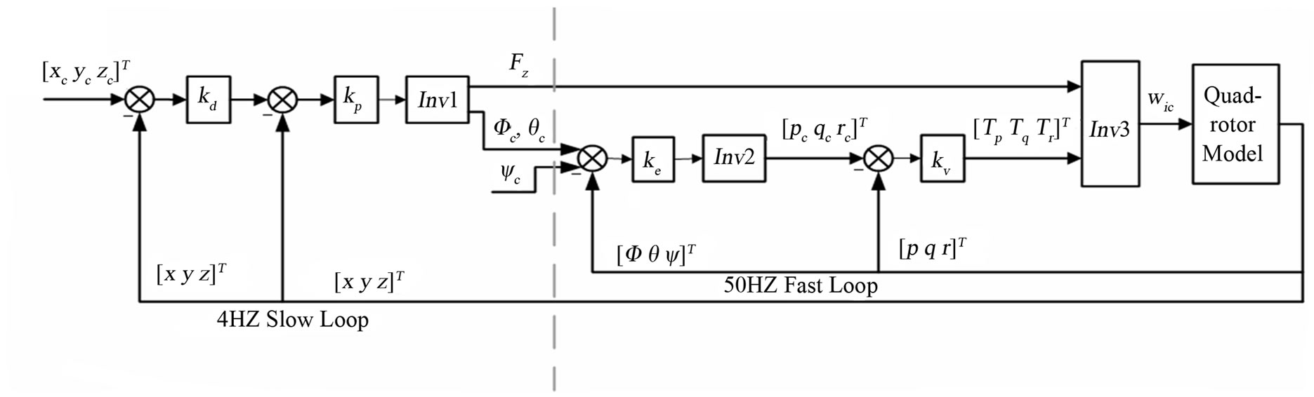
Figure 2. Improved dynamic inverse controller of hierarchical structure for quadrotor.
to approximate the continuous trajectory well. The slow loop frequency which depends on the response of translational motion and position sensor is about 4 Hz.
A given trajectory command signal include position command  and orientation command
 . We assumed that the pitch and roll angle are small enough to combine the formula (14) and (18). Then, symbol inv1 can be denoted by the relationship of attitude angle and position derivative as follows:
 (20)
(20)
Trajectory control is considered to exponentially stabilize the waypoint position error. Then the desired acceleration command would satisfy the relationship as follows:
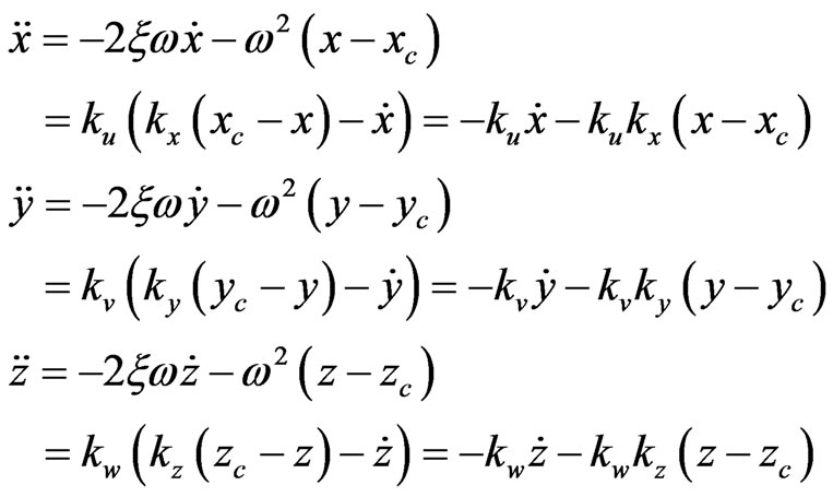 (21)
(21)
As depicted in Figure 2,  ,
,  is the damping factor and natural frequency of system, respectively. The factor
  and
and . From Equations (20) and (21) above, the control problem of quadrotor is addressed by decoupling the position control and attitude control, and position control of slow loop provides the attitude set points for the attitude controller of fast loop. We have testified that the desired system dynamics could be perfect when damping factor is constant 0.4 - 0.8. Only if the natural frequency of system required to aware, the controller factor can be quantified as follows:
 (22)
(22)
4.2. Fast Loop Control
Fast loop is attitude control loop which is required to response the change of attitude angle quickly. Its frequency which settled by system dynamics and control unit is 50 Hz.
Equation (17) can be transformed as follows:
 (23)
(23)
where the matrix inverse stands for symbol inv2. We can acquire  by expected attitude angle command
 .
.
Equation (15) can be transformed as follows:
 (24)
(24)
In Equation (24), the second item is intentionally omitted in order to maintain zero dynamics while angular velocity error is zero. Thus, the model error or unmodel dynamic characteristics in dynamic inverse method can be balanced through improving the dynamic inverse model. Though the proposed model of dynamic inverse is unaccurate, the zero dynamics can be kept even if the model is not valid. We can acquire  by expected attitude angle command
 .
.
In above formula, the factors  and
and  can be quantified in the same process. For example:
 (25)
(25)
The factor  and
and  is gained in the same formula.
4.3. Motor Speed Control
Equation (6) can be transform as follows:
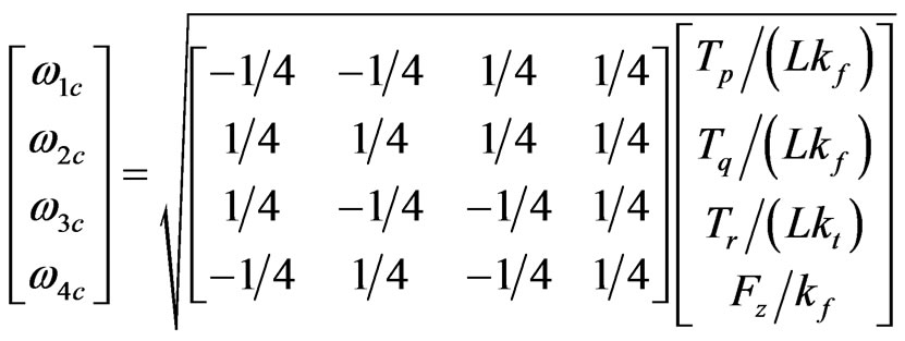 (26)
(26)
where the square root stands for symbol inv3.
5. Simulation Results
In this section, the demonstrating results are presented in order to observe the performances of proposed control principle. We considered a case of a rectangle shape trajectory-tracking problem. The parameters used for the aircraft model and the controller are given in Table 1. These parameters are referred to the quadrotor prototype designed by our lab, just refer Figure 3.
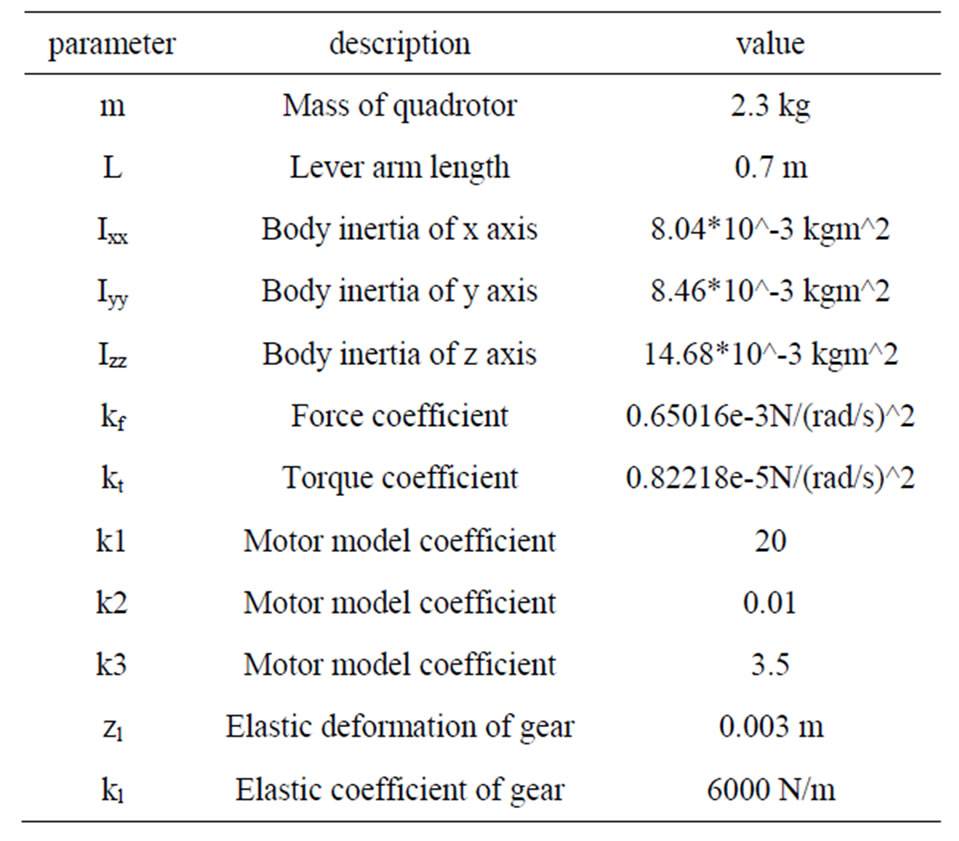
Table 1. Model parameters in demonstrator of quadrotor.
In the improving dynamic inverse controller, the parameters are defined as follows: The natural frequency of slow loop in Equation (21) is guessed as 1 Hz, the damping ratio is chosen as 0.72 according the experience in simulation. So the proportional parameters in controller are defined in Equation (22). In the same way, the natural frequency of pitch and roll attitude in Equation (25) is guessed as 10 Hz and the damping ratio is chosen as 0.7. But the natural frequency of yaw attitude is chosen as 2 Hz and damping ratio is chosen as 0.7.
The rectangle shape trajectory is 10 m × 15 m field with an altitude about 10 m altitude, the tracking simulation task is described as taking off ,tracking the rectangle shape trajectory, then landing. The results shown in Figure 4 illustrate the trajectory tracking performance of control strategy developed in this paper. The modeling difference between plant model and dynamic inverse controller include two aspects: no motor dynamic model in controller and 10% deviation of quadrotor body inertia and mass. But we can see the proposed controller behaves perfectly in Figure 4, except for the altitude due to quadrotor mass error.
6. Conclusion
The analysis presented here has shown the hover and
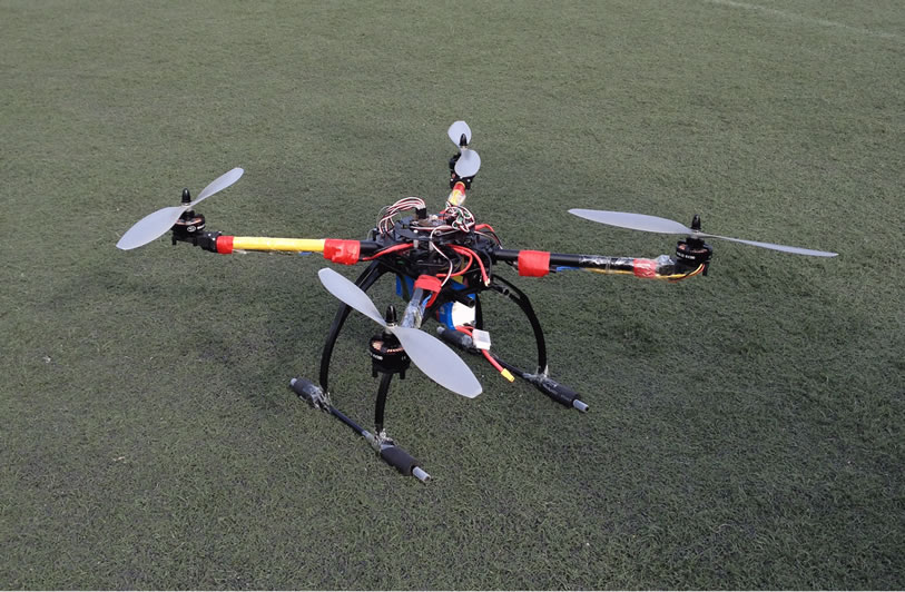
Figure 3. The demonstrator of simulating quadrotor.
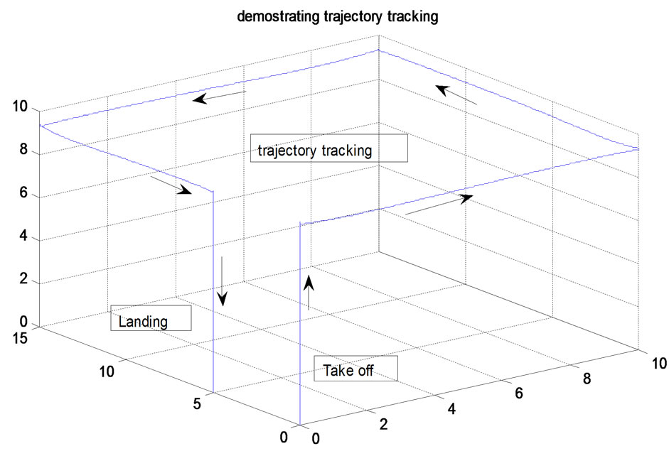
Figure 4. Illustrate the trajectory tracking performance of improved dynamic inverse strategy.
trajectory tracking capability of proposed controller. A nonlinear dynamic model of the quadrotor is provided, and a controller based on the improved dynamic inverse is synthesized for the purpose of stabilization and trajectory tracking. The proposed control strategy can balance the deviation of model inaccuracy.