 Journal of High Energy Physics, Gravitation and Cosmology, 2019, 5, 425-437 http://www.scirp.org/journal/jhepgc ISSN Online: 2380-4335 ISSN Print: 2380-4327 10.4236/jhepgc.2019.52024 Mar. 13, 2019 425 Journal of High Energy Physics, Gravitation and Cosmology An e + e − /γγ/ep Accelerator Complex at a Future Circular Collider Radoje Belusevic High Energy Accelerator Research Organization (KEK), Tsukuba, Japan This is the second paper by the author describing versatile accelerator com- plexes that could be built at a Future Circular Collider (FCC) in produce , and collisions. The facility described here features an ILC-based collider placed tangentially to the FCC tunnel. If the col- lider is positioned asymmetrically with respect to the FCC tunnel, electron (or positron) bunches could be accelerated by both linacs before they are brought into collision with the 50- TeV beams from the FCC proton storage ring (FCC-pp). The two linacs may also form a part of the injector chain for FCC-pp. The facility could be converted into a multi-MW beams for fixed-target experiments. Keywords Accelerator, Future Circular Collider (FCC), Experiments 1. Introduction The maximum luminosity at a circular collider, such as the proposed FCC-ee facility [1], is severely constrained by beamstrahlung effects at high energies; also, it is very difficult to achieve a high degree of beam polarization [2]. At the facilities described in this paper and [3], luminosity grows almost linearly with the beam energy [4] and the initial electron beam polarization can reach about 80% [5]. The availability of polarized beams is essential for some important precision measurements in and collisions [6]. The rich set of final states in and collisions would play an essential role in measuring the mass, spin, parity, two-photon width and trilinear self-coupling of the Standard Model (SM) Higgs boson, as well as its couplings to fermions and gauge bosons. Some of those measurements require centre-of-mass Belusevic, R. 9) An e + e − / γγ / ep Accelerator Com plex at a Future Circular Collider . Journal of High Energy Physics , G , , 425-437. https://doi.org/10.4236/jhepgc.2019.52024 January 27, 2018 March 10, 2019 March 13, 2019 9 by author(s) and Research Publishing Inc. This work is licensed under the Creative Commons Attribution International 4.0). http://creativecommons.org/licenses/by/4.0/ 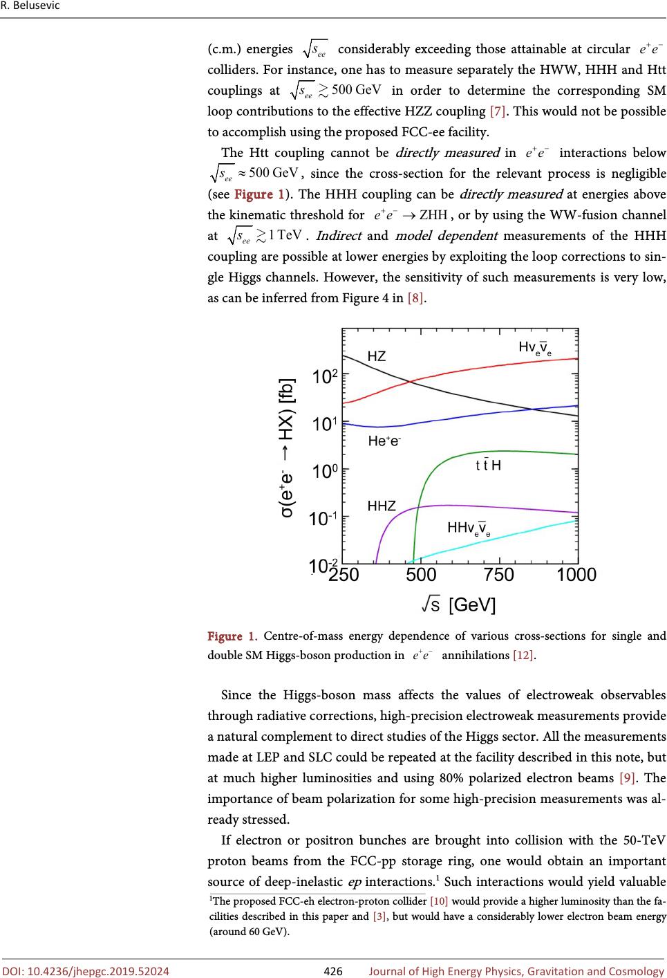 R. Belusevic 10.4236/jhepgc.2019.52024 426 Journal of High Energy Physics, Gravitation and Cosmology (c.m.) energies considerably exceeding those attainable at circular colliders. For instance, one has to measure separately the HWW, HHH and Htt couplings at in order to determine the corresponding SM loop contributions to the effective HZZ coupling [7]. This would not be possible to accomplish using the proposed FCC-ee facility. The Htt coupling cannot be directly measured in interactions below , since the cross-section for the relevant process is negligible (see Figure 1). The HHH coupling can be directly measured at energies above the kinematic threshold for , or by using the WW-fusion channel at . Indirect and model dependent measurements of the HHH coupling are possible at lower energies by exploiting the loop corrections to sin- gle Higgs channels. However, the sensitivity of such measurements is very low, as can be inferred from Figure 4 in [8]. Figure 1. Centre-of-mass energy dependence of various cross-sections for single and double SM Higgs-boson production in annihilations [12]. Since the Higgs-boson mass affects the values of electroweak observables through radiative corrections, high-precision electroweak measurements provide a natural complement to direct studies of the Higgs sector. All the measurements made at LEP and SLC could be repeated at the facility described in this note, but at much higher luminosities and using 80% polarized electron beams [9]. The importance of beam polarization for some high-precision measurements was al- ready stressed. If electron or positron bunches are brought into collision with the 50-TeV proton beams from the FCC-pp storage ring, one would obtain an important source of deep-inelastic ep interactions. 1 Such interactions would yield valuable 1 The proposed FCC-eh electron-proton collider [10] would provide a higher luminosity than the fa- cilities described in this paper and [3] , but would have a considerably lower electron beam energy (around 60 GeV). 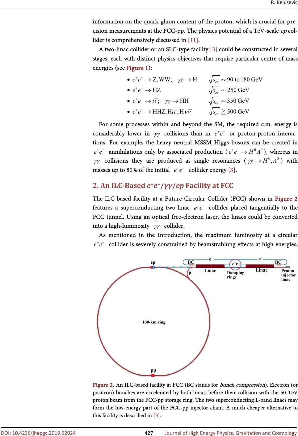 R. Belusevic 10.4236/jhepgc.2019.52024 427 Journal of High Energy Physics, Gravitation and Cosmology information on the quark-gluon content of the proton, which is crucial for pre- cision measurements at the FCC-pp. The physics potential of a TeV-scale ep col- lider is comprehensively discussed in [11]. A two-linac collider or an SLC-type facility [3] could be constructed in several stages, each with distinct physics objectives that require particular centre-of-mass energies (see Figure 1): Z,WW;H90 to180GeV HZ250 GeV ;HH350 GeV HHZ,500GH,eVH ee ee ee ee ees ees eetts eetts γγ γγ νν +− +− +− +− •→→ •→ •→→ •→ For some processes within and beyond the SM, the required c.m. energy is considerably lower in collisions than in or proton-proton interac- tions. For example, the heavy neutral MSSM Higgs bosons can be created in annihilations only by associated production ( ), whereas in collisions they are produced as single resonances ( ) with masses up to 80% of the initial collider energy [3]. 2. An ILC-Based e + e − /γγ/ep Facility at FCC The ILC-based facility at a Future Circular Collider (FCC) shown in Figure 2 features a superconducting two-linac collider placed tangentially to the FCC tunnel. Using an optical free-electron laser, the linacs could be converted into a high-luminosity collider. As mentioned in the Introduction, the maximum luminosity at a circular collider is severely constrained by beamstrahlung effects at high energies; Figure 2. An ILC-based facility at FCC (BC stands for bunch compression ). Electron (or positron) bunches are accelerated by both linacs before their collision with the 50-TeV proton beam from the FCC-pp storage ring. The two superconducting L-band linacs may form the low-energy part of the FCC-pp injector chain. A much cheaper alternative to this facility is described in [3].  R. Belusevic 10.4236/jhepgc.2019.52024 428 Journal of High Energy Physics, Gravitation and Cosmology also, it is very difficult to achieve a high degree of beam polarization. At the facilities described in this paper and [3], luminosity grows almost linearly with the beam energy and the electron beam polarization can reach 80%. The baseline parameters for the proposed ILC collider, shown in Table 1, re- flect the need to balance the constraints imposed by the various accelerator sub-systems, as explained in [13]. The rf power is provided by 10 MW mul- ti-beam klystrons, each driven by a 120 kV pulse modulator. The estimated AC power is 122 MW at and 163 MW at . The 1.3-GHz superconducting niobium rf cavities have average accelerating gra- dients of 31.5 MeV/m. Table 1. Baseline ILC parameters [13]. Centre-of-mass energy GeV 250 500 Pulse repetition rate Hz 5 5 Bunch population ×10 10 2 2 Number of bunches 1312 1312 Bunch interval ns 554 554 RMS bunch length ,ze σ mm 0.3 0.3 Norm. horizontal emittance at IP μm 10 10 Norm. vertical emittance at IP nm 35 35 Horizontal beta function at IP mm 13 11 Vertical beta function at IP mm 0.41 0.48 RMS horizontal beam size at IP nm 729 474 RMS vertical beam size at IP nm 7.7 5.9 Vertical disruption parameter 24.5 24.6 Luminosity 0.75 1.8 In order to maximize luminosity at low centre-of-mass energies, the beam power could be increased by increasing the pulse repetition rate while re- ducing the accelerating gradient of the main linacs. At , the power consumption of the main 250-GeV linacs is reduced by over a factor of two when they are running at half their nominal gradient. Under these condi- tions, one can run the accelerator at the maximum repetition rate of 10 Hz (de- termined by the cryogenic system and the beam damping time ms), thus doubling its luminosity. The two superconducting L-band linacs in Figure 2 may also form a part of the FCC-pp injector chain. Since the collider is positioned asymmetrically with respect to the FCC tunnel, electron (or positron) bunches could be accelerated by both linacs before they are brought into collision with the 50-TeV beams from the FCC-pp proton storage ring. The entire accelerator complex would serve as a source of , , pp and ep interactions. 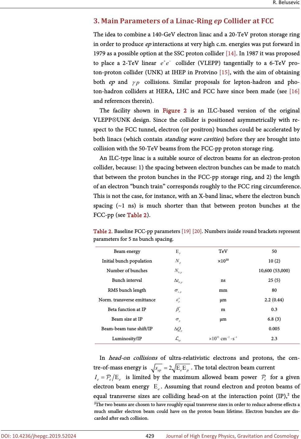 R. Belusevic 10.4236/jhepgc.2019.52024 429 Journal of High Energy Physics, Gravitation and Cosmology 3. Main Parameters of a Linac-Ring ep Collider at FCC The idea to combine a 140-GeV electron linac and a 20-TeV proton storage ring in order to produce ep interactions at very high c.m. energies was put forward in 1979 as a possible option at the SSC proton collider [14]. In 1987 it was proposed to place a 2-TeV linear collider (VLEPP) tangentially to a 6-TeV pro- ton-proton collider (UNK) at IHEP in Protvino [15], with the aim of obtaining both ep and collisions. Similar proposals for lepton-hadron and pho- ton-hadron colliders at HERA, LHC and FCC have since been made (see [16] and references therein). The facility shown in Figure 2 is an ILC-based version of the original VLEPP⊗UNK design. Since the collider is positioned asymmetrically with re- spect to the FCC tunnel, electron (or positron) bunches could be accelerated by both linacs (which contain standing wave cavities ) before they are brought into collision with the 50-TeV beams from the FCC-pp proton storage ring. An ILC-type linac is a suitable source of electron beams for an electron-proton collider, because: 1) the spacing between electron bunches can be made to match that between the proton bunches in the FCC-pp storage ring, and 2) the length of an electron “bunch train” corresponds roughly to the FCC ring circumference. This is not the case, for instance, with an X-band linac, where the electron bunch spacing (~1 ns) is much shorter than that between proton bunches at the FCC-pp (see Table 2). Table 2. Baseline FCC-pp parameters [19] [20]. Numbers inside round brackets represent parameters for 5 ns bunch spacing. Beam energy TeV 50 Initial bunch population ×10 10 10 (2) Number of bunches 10,600 (53,000) Bunch interval ns 25 (5) RMS bunch length mm 80 Norm. transverse emittance μm 2.2 (0.44) Beta function at IP m 0.3 Beam size at IP μm 6.8 (3) Beam-beam tune shift/IP 0.005 Luminosity/IP 2.3 In head-on collisions of ultra-relativistic electrons and protons, the cen- tre-of-mass energy is . The total electron beam current is limited by the maximum allowed beam power for a given electron beam energy . Assuming that round electron and proton beams of equal transverse sizes are colliding head-on at the interaction point (IP), 2 the 2 The two beams are chosen to have roughly equal transverse sizes in order to reduce adverse effects a much smaller electron beam could have on the proton beam lifetime. Electron bunches are di carded after each collision.  R. Belusevic 10.4236/jhepgc.2019.52024 430 Journal of High Energy Physics, Gravitation and Cosmology luminosity of the collider is given by [17] [18] 2* 4π e 4 π epp p e epc n ppp NNN I f γ σεβ =≡ (1) In these expressions, and are the electron and proton bunch popu- lations, respectively; is the bunch collision frequency; is a correction factor discussed below; and is the proton beam size at IP, ex- pressed in terms of the normalized proton beam emitance, , the proton beta function at IP, , and the Lorentz factor of the proton beam, . Note that the luminosity is proportional to the electron beam power ( e is the electron charge), the proton beam energy ( ), and the proton beam brightness . In Equation (1), is a product of three correction factors with values typi- cally close to unity: hourglasspinchfilling HHH≡⋅⋅ (2) The factor takes into account the filling patterns of the electron and proton beams. If the number of proton bunches and the bunch interval ns (see Table 2), the “length” of the proton beam is ns. This corresponds to 80 km, which means that only 80% of the FCC circum- ference is filled with proton bunches ( ). In this particular case 20% of the electron bunches would not collide with the proton beam. The factor accounts for a loss of luminosity when the bunch length is comparable to or larger than . The beta function grows parabolically as a function of distance s from the interaction point, which causes the beam size to increase: (3) As the beam size increases, the contribution to the luminosity from regions with large decreases ( hourglass effect ). For zero crossing angle and , () () 2 hourglass π eerfc x Hxxx= (4) with () () 2 * 2 , 2 2 ,erfced π 1 ep t e x zp ep xxt εε β σ εε ∞ − ≡= + ∫ (5) where and denote geometric emittances [11] [21] (the normalized emittance is invariant under acceleration); erfc(z) is the “complemen- tary error function” (defined as the area under the “tails” of a Gaussian distribu- tion). The enhancement factor in Equation (2) is due to the attractive beam-beam force . Since the electron bunch charge is relatively small and the proton energy is high, the beam-beam force acting on electrons has a much greater strength than that acting on protons. Consequently, the electron bunch is 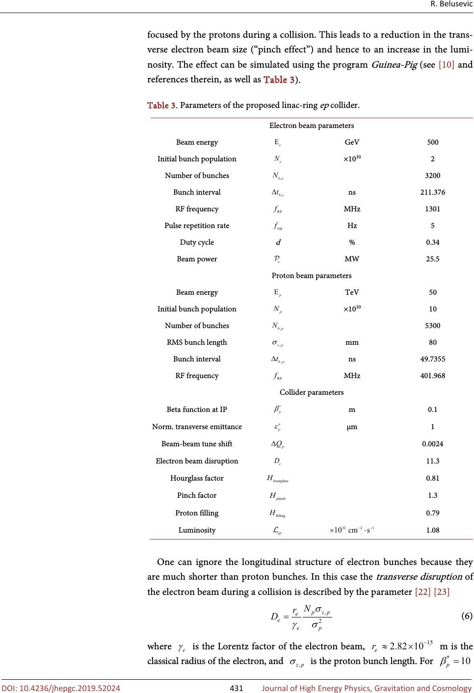 R. Belusevic 10.4236/jhepgc.2019.52024 431 Journal of High Energy Physics, Gravitation and Cosmology focused by the protons during a collision. This leads to a reduction in the trans- verse electron beam size (“pinch effect”) and hence to an increase in the lumi- nosity. The effect can be simulated using the program Guinea-Pig (see [10] and references therein, as well as Table 3). Table 3. Parameters of the proposed linac-ring ep collider. Electron beam parameters Beam energy GeV 500 Initial bunch population ×10 10 2 Number of bunches 3200 Bunch interval ns 211.376 RF frequency MHz 1301 Pulse repetition rate Hz 5 Duty cycle d % 0.34 Beam power MW 25.5 Proton beam parameters Beam energy TeV 50 Initial bunch population ×10 10 10 Number of bunches 5300 RMS bunch length mm 80 Bunch interval ns 49.7355 RF frequency MHz 401.968 Collider parameters Beta function at IP m 0.1 Norm. transverse emittance μm 1 Beam-beam tune shift 0.0024 Electron beam disruption 11.3 Hourglass factor 0.81 Pinch factor 1.3 Proton filling 0.79 Luminosity 1.08 One can ignore the longitudinal structure of electron bunches because they are much shorter than proton bunches. In this case the transverse disruption of the electron beam during a collision is described by the parameter [22] [23] (6) where is the Lorentz factor of the electron beam, m is the classical radius of the electron, and is the proton bunch length. For  R. Belusevic 10.4236/jhepgc.2019.52024 432 Journal of High Energy Physics, Gravitation and Cosmology cm, the disruption parameter can be as large as in an ep linac-ring collider (see Figure 3). Figure 3. Electron beam disruption parameter as a function of [18]. The plot was made for an ep collider based on LHC and an ILC-type electron linac. LHC * denotes an upgraded proton beam scenario (see Table 1 in [18]). As already mentioned, the luminosity of an ep collider is proportional to the proton beam brightenss (see Equation (1)). Together with a given bunch length and energy spread, the beam brightness is a measure of the phase-space density. In the low-energy part of a proton injector, the quantity is limited by space-charge forces that induce a transverse tune shift 3 (7) Here is the proton velocity and c is the speed of light in vacuo [24] [25]. In order to reduce the effect of space-charge forces at low energies and deliver proton bunches a few mm long, the facility in Figure 2 features a single 3-GeV proton injector linac similar to that currently being built at the European Spalla- tion Source (ESS) [26]. At high energies, the beam brightness in a storage ring slowly diminishes due to Coulomb scattering of protons within a bunch ( intra-beam scattering ) [27]. In the presence of dispersion (see footnote 4), the intra-beam scattering also leads to an increase in emittance. This sets the ultimate limit on the phase-space density in a proton storage ring. The growth of a beam of charged particles due to intra-beam scattering is characterized by the horizontal growth rate [28]. 3 The “tune” or Q value is defined as the number of betatron oscillations per revolution in a circular accelerator. The charge and current of a high-inensity beam in an accelerator create self- image fields that alter the beam dynamics and influence the single-particle motion as well as coh rent oscillations of the beam as a whole. The effect of space-charge forces is to change Q amount (“tune shift”) [24].  R. Belusevic 10.4236/jhepgc.2019.52024 433 Journal of High Energy Physics, Gravitation and Cosmology (8) where are the normalized beam emittances, and is the r.m.s. relative momentum . Note that the growth rate depends li- nearly on the normalized phase-space density. In the FCC-pp storage ring syn- chrotron radiation damping is expected to be much stronger than the in- tra-beam scattering, making the latter effect less of an issue [19]. The space-charge forces that limit the beam brightness are determined by the longitudinal charge density and thus by the proton bunch length . To attain maximum brightness, should be as large as possible. On the other hand, there is a loss of luminosity when the bunch length is comparable to or larger than (this hourglass effect was described earlier). Furthermore, the trans- verse disruption of the electron beam during an ep collision is proportional to , as shown in Equation (6). While optimizing the bunch length within these constraints, the beam stability must be preserved (see below). A particle in one colliding beam experiences a force due to the electromagnet- ic interactions with all the particles in the opposing beam. This force depends upon the displacement of the particle from the equilibrium orbit of the opposing bunch. For small particle displacements, the beam-beam interaction is nearly li- near, and its strength is characterized by a parameter known as the beam-beam tune shift [29]: * 2 4π 4 π pppe e p n epp rrN N Q β σγε ∆≡≈ (9) where m is the classical radius of the proton and was used. Since electron bunches are discarded after each collision, only the tune shift of the proton beam, , is considered here. The tune shift is approx- imately given by 10 3 6 10 1.210 10m e p n p N Q ε − − ∆≈×⋅ (10) The parameter must be limited to about in order to stem the emittance growth due to random fluctuations of the electron bunch parameters [30]. This imposes an upper limit of if one assumes m (see also Table 4 in [31]). A small error in the quadrupole gradient leads to a tune shift . To a beam particle with momentum it appears that all the quadrupoles in the ring have a quadrupole error proportional to [32]. The dimen- sionless quantity defined by is called the chromaticity of the beam optics. This quantity increases with the strength of the beam focusing. The main contribution to the chromaticity comes from the final focus quadru- poles, where the β -function is large [33]: (11)  R. Belusevic 10.4236/jhepgc.2019.52024 434 Journal of High Energy Physics, Gravitation and Cosmology Here , and denote the beta function, field gradient and length of the final quadrupole, respectively; is the focal length and the value of the vertical β -function at the interaction point. Thus, the chromaticity increases as decreases. Since grows linearly with the distance between the final-focus quadrupole and the interaction point, it is desirable to make this distance as small as possible. For the interaction region at an electron-proton collider, a novel design tech- nique called the achromatic telescopic squeezing (ATS) has been proposed “in order to find the optimal solution that would produce the highest luminosity while controlling the chromaticity, minimizing the synchrotron radiation power and maintaining the dynamic aperture required for [beam] stability” [34] [35] ( dynamic aperture is the stability region of phase space in a circular accelerator). The issue of beam stability was addressed earlier concerning the optimization of the proton bunch length. The proton bunches inside an ILC-type linac are much shorter than those inside the FCC storage ring (the 3-GeV injector linac mentioned earlier would deliver bunches a few millimetres long). Thus, has to be increased in order to attain the baseline FCC-pp value (see Table 2). In principle, the easiest way to increase the bunch length in a circular accelerator is to switch all RF systems off and let the bunches “decay” due to dispersion. 4 A faster and more subtle method—which could be implemented using a 3-TeV proton booster placed inside the FCC tunnel—is described in [36]. The expressions for beam-beam tune shift, electron beam disruption and beam growth rate given above do not accurately describe the time-dependent beam dynamics during collisions. To study the time-dependent effects caused by varying beam sizes, collision point simulations for linac-ring ep colliders have been performed using the ALOHEP software [37]. This numerical program op- timizes a set of electron and proton beam parameters in order to maximize lu- minosity [38]. The luminosity is independent of the electron bunch charge and the col- lision frequency as long as their product, expressed in terms of the beam power , is constant. One can therefore rewrite Equation (1) as follows [17] [39] 6 3021 11* 10m10cm250GeV 4.810cms 106622.6 MWE 10 pp e ep n e pp N γ εβ − −− =×⋅⋅⋅ (12) The electron beam current mA, where is the inverse of the bunch interval (see Table 3). The electron beam power MW, where d is the linac duty cycle. The proton beam current mA, and the total energy stored per proton beam is 4.2 GJ. To calculate , we set [35]. The value of was taken from [10]. 4 A particle with a momentum difference has a transverse position , where is the position a particle of nominal momentum would have and is the  R. Belusevic 10.4236/jhepgc.2019.52024 435 Journal of High Energy Physics, Gravitation and Cosmology Acknowledgements I would like to thank K. Yokoya for his valuable comments and suggestions. Conflicts of Interest The author declares no conflicts of interest regarding the publication of this pa- per. References [1] Blondel, A. and Zimmermann, F. A High Luminosity e + e − Collider in the LHC Tunnel to Study the Higgs Boson. CERN-OPEN-2011-047, arXiv:1112.2518. [2] Koratzinos, M. The FCC-ee Design Study: Luminosity and Beam Polarization. ar- Xiv:1511.01021v1. [3] Belusevic, R. (2017) An SLC-Type e + e − / γγ Facility at a Future Circular Collider. Journal of Modern Physics , 8, 1-16. https://doi.org/10.4236/jmp.2017.81001 [4] Boscolo, M., Delahaye, J.-P. and Palmer, M. The Future Prospects of Muon Collid- ers and Neutrino Factories. arXiv:1808.01858. [5] Aurand, B., et al. Beam Polarization at the ILC: The Physics Impact and the Accele- rator Solutions. Proceedings of the International Linear Collider Workshop ( LCWS 08 and ILC 08), Chicago, arXiv:0903.2959. [6] Moortgat-Pick, G., et al. , (2015) Physics at the e + e − Linear Collider. The European Physical Journal C , 75, 371. https://doi.org/10.1140/epjc/s10052-015-3511-9 [7] McCullough, M. An Indirect Model-Dependent Probe of the Higgs Self-Coupling. arXiv:1312.3322v6. [8] Di Vita, S., et al. A Global View on the Higgs Self-Coupling at Lepton Colliders. DESY 17-131, FERMILAB-PUB-17-462-T, arXiv:1711.03978. [9] Erler, J., et al. (2000) Physics Impact of GigaZ. Physics Letters B , 486, 125-133. https://doi.org/10.1016/S0370-2693(00)00749-8 [10] Bruning, O., et al. (2017) Future Circular Collider Study FCC-he Baseline Parame- ters. CERN-ACC-2017-0019. [11] Abelleira Fernandez, J.L. (2012) A Large Hadron Electron Collider at CERN: Report on the Physics and Design Concepts for Machine and Detector. Journal of Physics G : Nuclear and Particle Physics , 39, Article ID: 075001. https://doi.org/10.1088/0954-3899/39/7/075001 [12] Asner, D., et al. ILC Higgs White Paper. arXiv:1310.0763v3. [13] C. Adolphsen et al. The International Linear Collider Technical Design Report. Vol. 3, arXiv:1306.6328. [14] Weber, G., et al. (1979) Interaction Regions and Detectors for Electron Proton Ex- periments at 140 GeV + 20 TeV . Proceedings of 2 nd ICFA Workshop on Possibili- ties and Limitations of Accelerators and Detectors , Les Diablerets, 4-10 October 1979, 199-221. [15] Alekhin, S.I., et al. (1987) Prospects of the Future ep Colliders . IHEP Preprint 87-48, Serpukhov. [16] Akay, A.N., Karadeniz, H. and Sultansoy, S. (2010) Review of Linac-Ring-Type Col- lider Proposals. International Journal of Modern Physics A , 25, 4589-4602. https://doi.org/10.1142/S0217751X10049165  R. Belusevic 10.4236/jhepgc.2019.52024 436 Journal of High Energy Physics, Gravitation and Cosmology [17] Tigner, M., Wiik, B. and Willeke, F. (1991) An Electron-Proton Collider in the TeV Range. Proc. 1991 IEEE Part. Accel. Conf. , San Francisco, CA. [18] Zimmermann, F., et al . (2008) Linac-LHC ep Collider Options. Proceedings of EPAC , Genoa, 847-2849. [19] Benedikt, M., Schulte, D. and Zimmermann, F. (2015) Optimizing Integrated Lu- minosity of Future Hadron Colliders. Physical Review Special Topics — Accelerators and Beams , 18, Article ID: 101002. https://doi.org/10.1103/PhysRevSTAB.18.101002 [20] Zimmermann, F. (2015) High-Energy Physics Strategies and Future Large-Scale Projects. Nuclear Instruments and Methods in Physics Research Section B , 355, 4-10. https://doi.org/10.1016/j.nimb.2015.03.090 [21] Furman, M.A. (1991) Hourglass Effects for Asymmetric Colliders. IEEE Particle Accelerator Conference , San Francisco, 6-9 May 1991, 422-424. https://doi.org/10.1109/PAC.1991.164321 [22] Yokoya, K. and Chen, P. (1992) Beam-Beam Phenomena in Linear Colliders. Springer, Berlin, 415-445. [23] Hao, Y. and Ptitsyn, V. (2010) Effect of Electron Disruption in the Energy Recovery Linac Based Electron Ion Collider. Physical Review Special Topics — Accelerators and Beams , 13, Article ID: 071003. https://doi.org/10.1103/PhysRevSTAB.13.071003 [24] Schindl, K. (1999) Space Charge. Proceedings of Joint US - CERN - Japan - Russia School on Particle Accelerators , Beam Measurements , Montreux, 127-151. https://doi.org/10.1142/9789812818003_0004 [25] Benedikt, M. and Garoby, R. (2005) High Brightness Proton Beams for LHC: Needs and Means. CERN-AB-2005-009. [26] Danared, H., Lindroos, M. and Theroine, C. (2014) ESS: Neutron Beams at the High-Intensity Frontier. CERN Courier, 21-24 June. [27] Piwinski, A. (1975) Intra-Beam Scattering. 9 th International Conference on High Energy Accelerators , Stanford, 405. [28] Parzen, G. (1987) Intrabeam Scattering at High Energies. Nuclear Instruments and Methods in Physics Research , Section A , 256, 231-240. https://doi.org/10.1016/0168-9002(87)90213-0 [29] Ruggiero, F. and Zimmermann, F. (2002) Luminosity Optimization near the Beam-Beam Limit by Increasing Bunch Length or Crossing Angle. Physical Review Special Topics — Accelerators and Beams , 5, Article ID: 061001. https://doi.org/10.1103/PhysRevSTAB.5.061001 [30] Brinkmann, R. (1998) Interaction Region and Luminosity Limitations for the TESLA/HERA e/p Collider. Turkish Journal of Physics , 22, 661-666. [31] Yavas, Ö. (1998) Tune Shift Limitations for Linac-Ring Type Colliders. Turkish Journal of Physics , 22, 667-673. [32] Wille, K. (2000) The Physics of Particle Accelerators. Oxford Univ. Press, Oxford. [33] Zimmermann, F. (2002) Accelerator Physics and Technologies for Linear Colliders. Physics 575 Lecture Notes, University of Chicago, Chicago. [34] Fartoukh, S. (2013) Achromatic Telescopic Squeezing Scheme and Application to the LHC and Its Luminosity Upgrade. Physical Review Special Topics — Accelerators and Beams , 16, Article ID: 111002. https://doi.org/10.1103/PhysRevSTAB.16.111002  R. Belusevic 10.4236/jhepgc.2019.52024 437 Journal of High Energy Physics, Gravitation and Cosmology [35] Cruz-Alaniz, E., et al . (2015) Design of the Large Hadron Electron Collider Interac- tion Region. Physical Review Special Topics — Accelerators and Beams , 18, Article ID: 111001. https://doi.org/10.1103/PhysRevSTAB.18.111001 [36] Damerau, H. (2005) Creation and Storage of Long and Flat Bunches in the LHC. Ph.D. Thesis, Technical Univ. Darmstadt, Darmstadt. [37] ALOHEP. https://alohep.hepforge.org [38] Acar, Y.C., et al . (2017) Future Circular Collider Based Lepton-Hadron and Pho- ton-Hadron Colliders: Luminosity and Physics. Nuclear Instruments and Methods in Physics Research Section A , 871, 47-53. https://doi.org/10.1016/j.nima.2017.07.041 [39] Katz, U., Klein, M., Levy, A. and Schlenstedt, S. (2001) The THERA Book. DESY 01-123F, Vol. 4, DESY-LC-REV-2001-062.
|