Open Journal of Civil Engineering
Vol.2 No.3(2012), Article ID:23001,7 pages DOI:10.4236/ojce.2012.23022
Prediction of Reinforcement Effect by Screw on Triangular Embedment Perpendicular to the Grain with Variation of Screw Locations
Research Institute for Sustainable Humanosphere (RISH), Kyoto University, Kyoto, Japan
Email: murakamisatoru@rish.kyoto-u.ac.jp
Received August 1, 2012; revised September 2, 2012; accepted September 14, 2012
Keywords: Screw; Reinforce; FEA; Rotational Performance; Timber Structure
ABSTRACT
In this study, the reinforcement by screws for the wood perpendicular to the grain subjected to a rotational moment has been studied. For the estimation of rotational stiffness and yield moment, the reinforcement effect by the screws which varies depending on their position under the bearing plate was evaluated by taking the internal displacement distribution of the wood into account. The Finite Element Analysis (FEA) was used to investigate the internal displacement distribution of the wood. Then an appropriate function was found out to meet well with various internal displacement distributions under the bearing plate. The equations, which can estimate rotational stiffness and yield moment of the bearing performance of the wood reinforced by screws, were derived from the shear resistance mechanism between the screw and wood by considering their relative displacement distribution. Then rotational tests were carried out with the wood reinforced by the screws, setting screw thread at the various positions. Agreements between prediction and experimental results were very well. It was found that the screw reinforcement was effective, provided screw length should be longer for the wood height.
1. Introduction
The compression performance of wood perpendicular to the grain is remarkably inferior to that of wood parallel to the grain. In the case of the portal frame of through-bolt type as shown in Figure 1 (on the left), the end grain of the beam and the steel plate will be embedded in the side surface of column triangularly.
In order to improve the joint performance of timber structures, the enhancement of the bearing performance might be one of the possible choices. It is an effective method to insert the screws into the wood perpendicular to the grain as shown Figure 1. Therefore the studies on the screw reinforcement of bearing performance by inserting screws in the direction perpendicular to the wood grain has been carried out [1-3].
In reference [3], we have introduced a calculation method of stiffness and strength for screw reinforcement by considering the position of the thread of the screws. It was found that the effect of screw reinforcement varied depending on the position of screws thread. This was thought due to the inner displacement distribution on partial compression.
Since it was reported in the previous study [4] that there were outstanding differences on inner stress distribution of the wood depending on the cases subjected to uniform compression or triangular compression by the rotational moment, it was assumed that the tendency of inner displacement will not be the same for both cases. Although previous studies [1-3] focused on only uniform embedment case, as triangular embedment caused by moment resisting joint in portal frame structure has been getting interests among Japanese timber engineers recently, we intended to treat with triangular case.
In this study, assuming continuous column and column cut up to the same level as the upper surface of beam, the performance of the wood perpendicular to the grain deformed triangularly when they are received rotational moment was studied. Hereinafter we call them as continuous beam and cantilever beam respectively. It is because the stress distribution on the bearing area may be different depending on with and without the extend part of the wood. Then, the mechanical model with the screw reinforcement of rotational performance of the wood is proposed by considering the internal displacement distribution of the wood obtained by FEA.
2. Mechanical Model
In the case where the wood reinforced by the screws is subjected to rotational moment as shown in Figure 2, the resistance moment due to embedment resistance of wood (MW) and that due to individual screw (MS) are assumed to be independent. Hence, the total moment resistance can be expressed by Equation (1).
 (1)
(1)
In Equation (1), M is the total moment resistance and n is the number of inserted screws.
Because M is the function of the rotational angle (θ), therefore, the total rotational stiffness (R) is obtained from rotational stiffness of the wood (RW) and that of the screws (RS) as shown in the Equation (2).
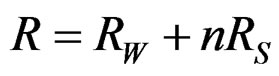 (2)
(2)
Ms can be expressed as multiplying the distance of the screw form the rotational centre (xi) and the resistance force (PS).
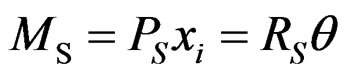 (3)
(3)
Then, θ can be expressed as below by using the displacement on the wood surface (δi) and xi.
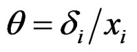 (4)
(4)
Then, RS can be shown by using the PS obtained from
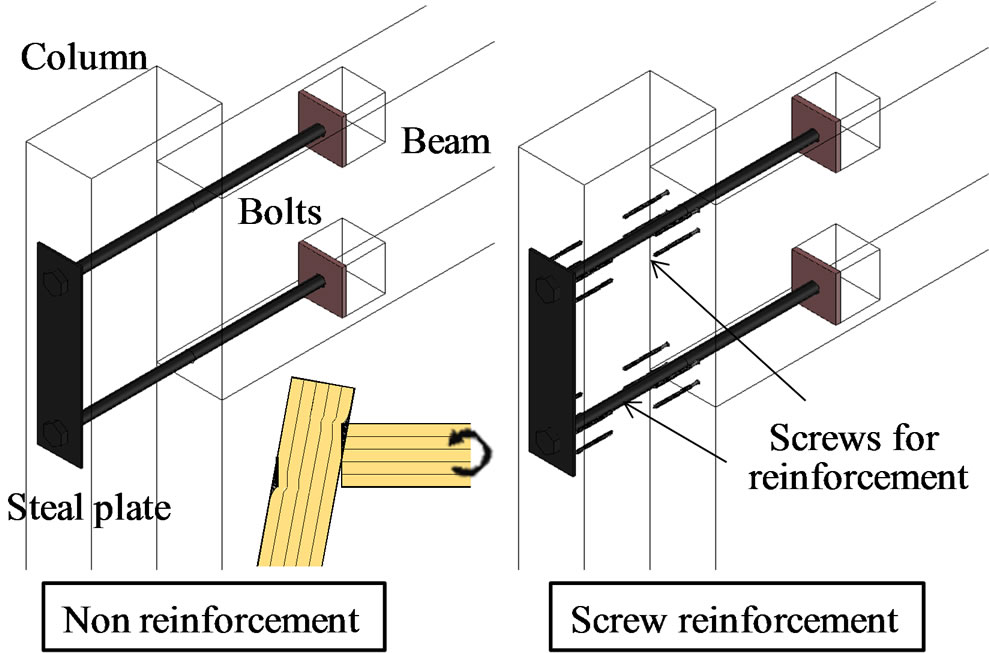
Figure 1. The models of portal frame of through-bolt type.
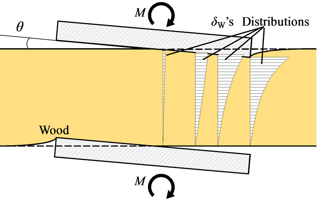
Figure 2. Distributions of compression displacement of wood.
previous study [3]. And, the displacement distribution of wood (δW) can be written as Equation (6).
 (5)
(5)
 (6)
(6)
Here, “a” and “b” are the positions on the vertical axis (z-axis) at the beginning and end of the thread. And ηis the function to decide the form of the displacement distribution and is obtained as follows.
 (7)
(7)
In the case of the uniform embedment, the value of α in Equation (7) is denoted as mentioned in previous study [3]. While in the case of triangular embedment, the value of α must be different from uniform case. Therefore, FEA was carried out in order to obtain the value of α for triangular embedment in the next chapter.
The yield rotational angle can be defined as the deformation angle of the wood when whichever the screws or the wood reaches to the yield displacement earlier.
 (8)
(8)
where:  is the yield displacement of the wood. The yield strength (My) can be obtained by using the total initial stiffness (R) as follows.
 (9)
(9)
3. Materials and Methods
3.1. Finite Element Analysis
3.1.1. Continuous Wood Beam
In order to decide the function of η, two-dimensional elastic analyses for the wood subjected to triangular embedment at the centre were conducted using commercially available FEA software “MSC’s Marc (Ver. 2011)”. Detecting influence of the distributions of δW, the width of the bearing plates, L was varied from 30 to 150 mm as a parameter.
The configuration of the wood analysed is shown in Figure 3. The centre of the wood was put between two rigid bodies and the wood forced to be deformed triangularly by letting two rigid bodies rotated with 0.001 rad, whose rotational centers were at the centers of the wood surface contacting with each rigid body. This moment makes triangle deformation to the wood. Since the internal displacement on the z direction at the any positions hardly changed even if the friction coefficient changed, the friction coefficient was set to zero which was easier for computation only to acquire the reinforcement effect of the screws.
Five different widths ranging from 0.3 to 1.5 times of the height (z0) were modeled. The end distance was set at 400 mm, referring to report by Madsen [5]. Sitka Spruce (Picea sitchensis) was used for the specimen as the experimental verification. The material constants inputted into FEA are indicated in Table 1, referring to [6].
3.1.2. Cantilever Wood Beam
The configuration of the wood analysed by FEA is shown in Figure 4 in accordance with [5]. The edge distance in each condition is 400 mm. Five different widths ranging from 0.3 to 1.5 times of z0 were modeled. The other test conditions are the same as those of the pervious clause.
3.2. Rotation Tests
3.2.1. Continuous Wood Beam
The steel frame used for the rotational test of the wood is

Figure 3. Configuration of the wood analysed by FEA (Continuous beam).

Figure 4. Configuration of the wood analysed by FEA (Cantilever beam).
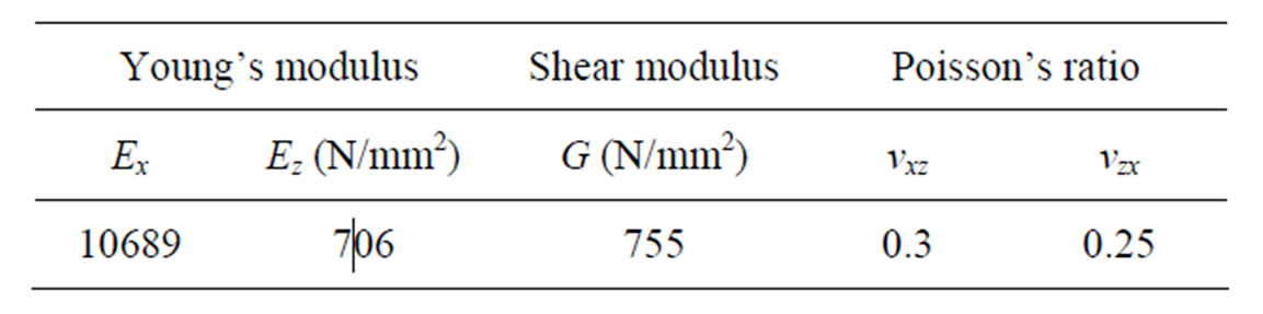
Table 1. Elastic constants.
shown in Figure 5. Every corner point was pin jointed. By applying the force to the top of the frame horizontally a rotational moment is induced in the wood. The steel plates directly contacted to the wood were not fixed to the centre jig mechanically. Because two 0.2 mm thick polytetrafluoroethylene sheets were placed between the two steel plates and steel frame to avoid the influence of friction, the steel plates contacted with the wood specimen can be slid freely.
Two screws were inserted on the both sides of the wood 90 mm apart from the centre of specimen as shown in Figure 5. Since two parts on the wood to be embedded, 4 screws in total were inserted each specimen.
In order to change the positions of the thread on z-axis in the wood, four types of the screws with four different lengths respectively were used (Figure 6), having the equal thread length of 20 mm. Also, the condition of inserting the full-threaded screws with the length of 50 mm (F50) was used for the test. After inserting the screw up to the designated position, the protruded parts of the screws over the wood surface were cut off with a grinder.
Glulam of spruce (density in dry condition: 409.3 ± 46.2 kg/m3, moisture Content: 12.2% ± 0.8%) with the dimensions of 1000 (L) × 100 (R) × 50 (T) [mm] was used.
The screws with outer and inner diameters of its thread, 6.2 and 4.4 mm respectively, were inserted, 90 mm apart from the rotational centre. Transducers (Tokyosokki’s CDP-10) were put on the asymmetrical opposite sides, 95 mm apart from the centre of specimen to measure the rotation due to the embedment.
For comparison, the wood without the screws was also

Figure 4. Configuration of the wood analysed by FEA (Cantilever beam).
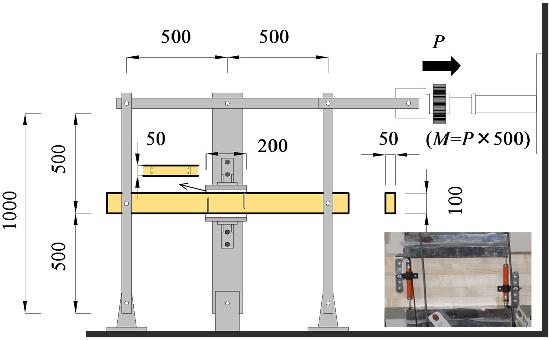
Figure 5. Rotational test set-up (Continuous beam).
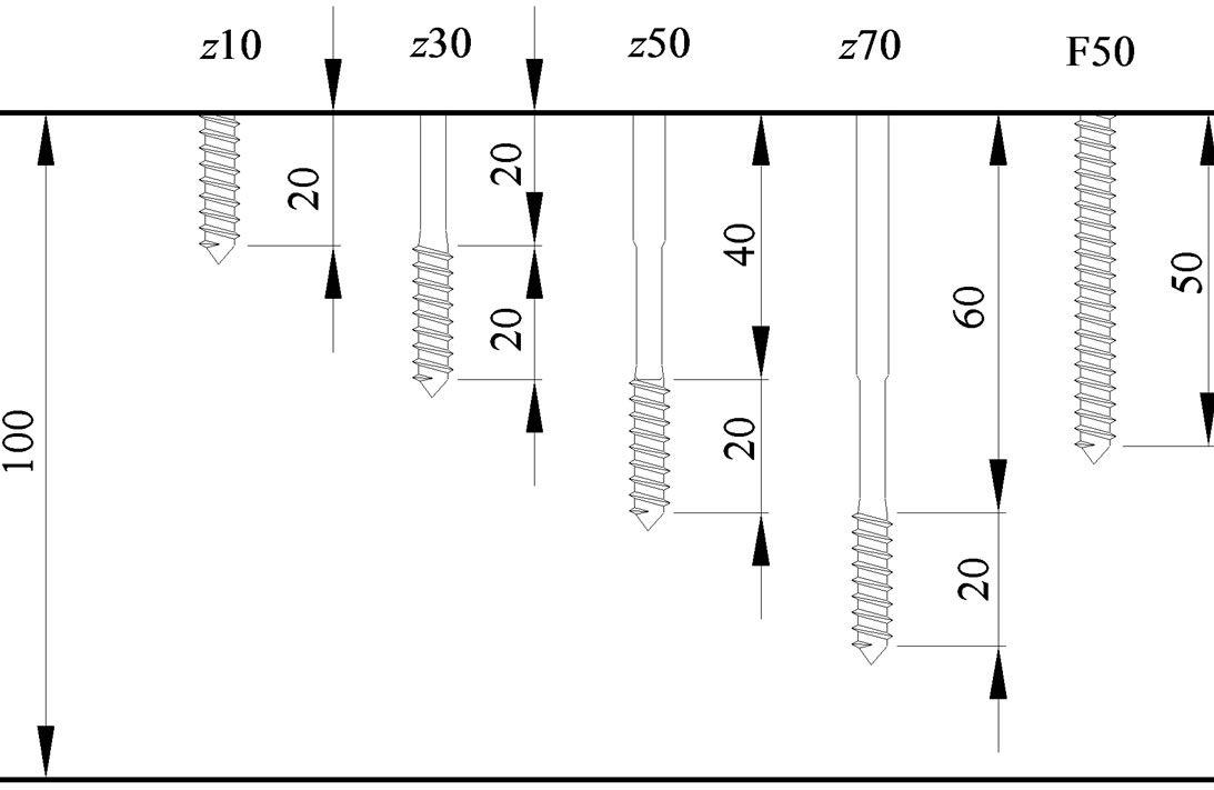
Figure 6. Positions of the thread on z-axis.
tested. Six replications were prepared for each condition. The rotational moment was applied at the constant speed of 1/1000 rad/min.
The moment was calculated by multiplying the load measured by the load cell and the vertical distance between the centre of the specimen and the load cell. The rotational stiffness and yield moment in the condition without the screws (RW and MW_y) were calculated by using the automatic extraction program “PICKPOINT [7]” as shown in Figure 7.
3.2.2. Cantilever Wood Beam
Figure 8 shows the test set up for cantilever type specimen. The test parameter was also the position of the thread in the vertical axis (z) as shown in Figure 6. The other test conditions are the same as those of the pervious clause.
4. Results and Discussion
4.1. Finite Element Analysis
4.1.1. Continuous Wood Beam
The FEA results are shown in Figure 9, as continuous lines. The vertical axis shows the z-directional position of the wood and the horizontal values indicates displacement in each location apart from the centre to that of the edge on the bearing area. The forms of the distribution become being arched as much as distant from the specimen centre on x-axis.
The unknown parameter α in Equation (7) was determined as 5.11 by employing least squares method so as to fir with FEA results. This value was rounded off to the natural number of 5. The displacement distributions calculated by Equation (8) using α = 5 were shown as open circles in Figure 9.
4.1.2. Cantilever Wood Beam
The FEA results are shown in Figure 10. The displacement distributions with the same distance from the centre of with and without the extra wood part were added at

Figure 7. Calculation method of RW and MW_y.
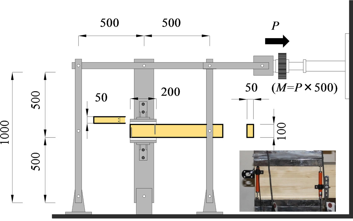
Figure 8. Rotation test (Cantilever beam).

Figure 9. Displacement distribution on each cross-section (Continuous beam).

Figure 10. Displacement distribution on each cross-section (Cantilever beam).
the same place with reversing the condition of the side without the extra length.
The unknown parameter α in Equation (7) was determined as 4.87 by employing least squares method so as to fir with FEA results. Also, this value was rounded off to the natural number of 5 .The displacement distributions calculated from Equation (7) in which the value of α was substituted the number of 5 were shown as open circles in Figure 10.
Then, it is concluded that the number of 5 is appropriate for the value of α regardless of the extra wood part.
4.2. Rotation Tests
4.2.1. Continuous Wood Beam
Figure 11 shows the relationships between the rotation moment and rotational angle (M-θ relationship). And Figures 12 and 13 show the comparisons between experimental results and predicted results in rotational stiffness and yield moment respectively. For the prediction of rotational stiffness and yield moment, the date of the screw shown in Table 2" target="_self"> Table 2 and the rotational stiffness and yield moment without screw reinforcement were substituted into Equations (8) and (9). These characteristic values of screw were obtained by using the same test and calculation methods in [3].
Comparison between the results for with and without the screw reinforcement, the improvement in strength is

Figure 11. M-θ relationships (Continuous beam).
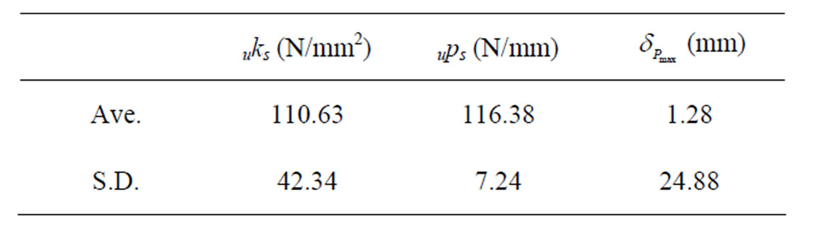
Table 2. Characteristics value of screw.

Figure 12. Comparison in rotational stiffness.
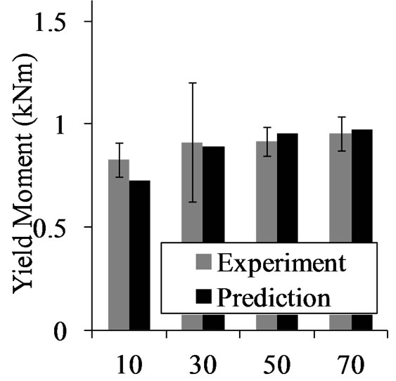
Figure 13. Comparison in rotational moment.
obvious. As concerns M-θ relationships with screw reinforcement, their characteristics become near to ideal elasto-plastic behavior. In the case where the screw length was short for the wood height, the reinforcement effect is very lower. While, the reinforce effect increase with choosing longer screw. Longer screw increases the rotational stiffness. While the yield moments of z-70 are smaller than those of z-50. And it can be conclude that the experimental results were well predicted by the equations derived in this study.
4.2.2. Cantilever Wood Beam
The curves of M-θ relationships on the conditions with the full-threaded screw were shown in Figure 14. These two graphs indicate the condition of continuous and cantilever beams respectively. Because the pull-out performance of the full-threaded screw shows sudden decrease of the resisting force, the moment gradually decreased after reaching the maximum point.
Since there is no extra wood part on the one side in the case of the cantilever and the embedded volume in the case of cantilever beam is smaller than that in the case of the continuous beam, the moment of the continuous beam is a little bit higher than that of cantilever beam if they are the same rotational angle. But, as introduced earlier, it is considered that the effect of the screw were the same between them.
Figures 15 and 16 show the features of continuous beam and cantilever beam reinforced by the full-thread screws rotated by 0.005 rad. respectively. In these tests, no brittle failures were observed. However, in order to

Figure 14. M-θ Relationships on the conditions of F50.
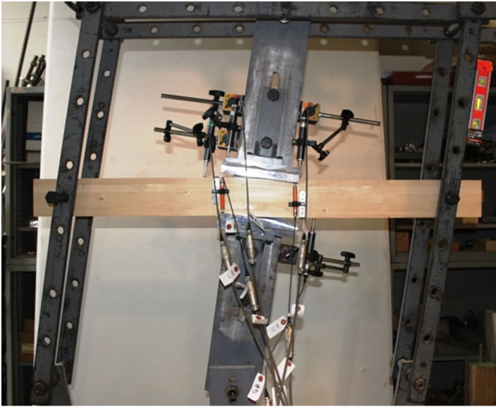
Figure 15. Continuous beam rotated by 0.005 rad.

Figure 16. Cantilever beam rotated by 0.005 rad.
prevent brittle failure due to excessive number of screws, it is required to use appropriate numbers of screws.
Figure 17 shows M-θ relationships of cantilever beam. And, Figures 18 and 19 show the comparisons between experimental results and predicted results in rotational stiffness and yield moment respectively. In the case where the screw length for the wood height was short, the reinforce effect is very lower same as the case of the continuous beam. However, it can be concluded that the longer screws for the wood height are, the higher performance of screw reinforcement can be obtained.
While, in the case where the length of the inserted screw is too long, the declines of the yield moments were observed as well as the case of Continuous beam. It is thought that the reason of decline is because of the short length of the wood under the screw. This point should be noticed.

Figure 17. Relationships between moment and rotational angle (Cantilever beam).

Figure 18. Comparison in rotational stiffness.

Figure 19. Comparison in rotational moment.
5. Conclusion
Regardless the length of the extra wood part where in not subjected to the rotational moment directly, the value of 5 is appropriate for α which decide the shape of the displacement distributions of the inner wood from the FEA results. From the rotation tests on both continuous and cantilever beam specimens, the reinforce effect is high in the case where the screw length is long. Proposed equations appear to be satisfactory to predict the rotational stiffness and yield moment of the wood reinforced by screws.
6. Acknowledgements
Thanks are due to Kokubu Corp. for donations of screws. In this research work we used the supercomputer of ACCMS, Kyoto University.
REFERENCES
- I. Bejtka and H. J. Blass, “Self-Tapping Screws as Reinforcements in Beam Supports,” CIB-W18, Florence, 2006.
- I. Bejtka, “Verstärkung von Bauteilen aus Holz mit Vollgewindeschrauben,” Band 2 der Reihe Karlsruher Berichte zum Ingenieurholzbau. Herausgeber, Karlsruhe University, Karlsruhe Germany, 2005 (In German).
- S. Murakami, A. Kitamori, K. Jung, I. B. Hassel and K. Komatsu, “Prediction of Reinforcement Effect by Screws on Compression Performance of Wood Perpendicular to the Grain,” Open Journal of Civil Engineering (Accepted).
- A. Kitamori, K. Jung, Y. Kataoka and K. Komatsu, “Effect of Additional Length on Partial Compression Perpendicular to the Grain of Wood: Difference among the Supporting Conditions,” Journal of Structural and Construction Engineering, Vol. 74, No. 642, 2009, pp. 1477- 1485 (In Japanese).
- B. Madsen, R. F. Hooley and C. P. Hall, “A Design Method for Bearing Stresses in Wood,” Canadian Journal of Civil Engineering, Vol. 9, No. 2, 1982, pp. 338-349. doi:10.1139/l82-035
- Forest Research Institute of Forestry Agency, “Handbook of Wood Industry,” Maruzen, Tokyo, 1982 (In Japanese).
- M. Karube, M. Harada and T. Hayashi, “A Proposal of Bi-Linear Modeling Tool for Assess Its Method and Problems in Common Tool for Load-Deformation Curves of Wooden Structures,” Digests of Annual Meeting of Architectural Institute of Japan, C-1, III, 2001, pp. 215- 216 (In Japanese).