Journal of Water Resource and Protection
Vol. 5 No. 5 (2013) , Article ID: 31828 , 9 pages DOI:10.4236/jwarp.2013.55055
Investigation of a Flow Modulation System for Siphonic Roof Drainage Systems
School of the Built Environment, Heriot Watt University, Edinburgh, UK
Email: d.p.campbell@hw.ac.uk
Copyright © 2013 David P. Campbell. This is an open access article distributed under the Creative Commons Attribution License, which permits unrestricted use, distribution, and reproduction in any medium, provided the original work is properly cited.
Received February 17, 2013; revised March 19, 2013; accepted April 8, 2013
Keywords: Siphonic Roof Drainage System; Rainfall; Climate Change; Modulated Flow
ABSTRACT
Siphonic roof drainage systems (SRDS’s) have been widespread used now for approximately 40 years and are an efficient method of removing rainwater rapidly from roofs. SRDS’s are designed to run full-bore, resulting in sub-atmospheric system pressures with high hydraulic driving heads and higher system flow velocities than conventionally guttered systems. Hence, SRDS’s normally require far fewer downpipes, and the depressurised conditions also mean that much of the collection pipework can be routed at a high level, thus reducing the extent of any underground pipework. But, they work properly at only one roof run-off rate and therefore suffer from sizing and operational problems including noise and vibration which limit their performance and adoption rate. Climate change is creating situations where normal ranges of rainfall intensity are being frequently exceeded, so the typical:storm ratios (rTS) are large increasing. Current SRDS’s typically operate within a small rTS range of 2. This may have an impact on the future uptake of SRDS’s. This paper describes the development of a novel SRDS which includes a small mobile cap at the roof of outlet appears to offer benefits and avoids sizing problems associated with current SRDS’s. The cap has the potential to avoid noise associated with making and breaking siphonic action through flow modulation. Laboratory scale tests demonstrate the basic feasibility of the cap system and indicate that the cap functions reliably. This research received no specific grant from any funding agency in the public, commercial, or not-for-profit sectors. Basic on sizing and design optimization factors are suggested. The rTS range is increased from approximately 2 to approximately 6.
1. Introduction
Despite the availability of Sustainable Urban Drainage Systems (SUDS), which includes green roofs and other such tools, to reduce, attenuate and treat urban runoff, substantial areas of the urban environment are impermeable and drain rapidly; namely roof surfaces [1]. The design of the roof surface is usually within the remit of the architect rather than the drainage designer and structural concerns often taken precedence over performance criteria [1]. Due to this roof drainage systems (RDS’s) do not necessarily receive the attention they deserve. The cost of a RDS is usually a small proportion of a building’s total cost [2]. The initial cost can be far outweighed by the costs of the damage and disruption, which may result from a failure of the system to provide the necessary degree of protection.
There are two predominant types of RDS, namely conventional and Siphonic (SRD’s) and Conventional (CRDS’s). CRDS’s operate at atmospheric pressure and the driving head is thus limited to the gutter flow depths. In contrast, siphonic roof drainage systems (SSRDS’s) are designed to run full-bore, resulting in sub-atmospheric system pressures, higher driving heads and higher system flow velocities.
Despite with these advantages, SRDS’s are limited to operating efficiently at only one flow rate, which is obviously linked to roof geometry and rainfall intensity. In addition to the natural variation in rainfall intensity, climate change is altering rainfall patterns even further. Rainwater falling on roofs arrives in a range of timedependant rates, from “typical” through to “storm” [3]. For each climatic region on Earth, the ratio between these rates will have a statistically derived range, defined in this application as the typical:storm ratio, or rTS. Tropical locations will have an rTS of approximately 6, while temperate locations such as the UK have an rTS of approximately 3 [4,5]. Since current SRDS’s work properly at only one rainfall rate, such a system can only be designed to operate in its design state with an rTS value of between 1 and 3. It is up to the designer to select a system size which is, at best, a compromise which will minimise the risks of flooding and ponding [6]. The innovation described in this application will allow system operation over a very wide range of rTS values, allowing full siphonic action for a wide range of rainfall rates and effectively no rTS limit.
The key advantage which CRD’s maintain over SRDS’s is their ability to operate as effectively at sub-design rainfall events as the design event. Furthermore CRDS having inherent spare capacity, as their vertical downpipes, are designed to run at or below 33% full. This implies that CRDS are over engineered and therefore they are wasteful of resources, space and cost.
This paper describes an innovation which may reduce the generation of noise and structural vibration within SRDS’s, through the use of a mobile cap placed above the roof outlet. By linking this cap to a lever and counterweight, the potential exists to allow siphonic action a range of rTS values, instead of just one.
2. Siphonic Roof Drainage Systems
2.1. Basic Siphon Systems
Siphonic roof-drainage systems (SRDS’s) are a popular method of transferring rainwater from roof level to the ground, with an estimated 10,000 systems now installed in the UK. Their use is particularly well established for large steel-framed buildings with restricted numbers of internal columns [7].
SRDS’s were developed in the 1960s in Scandinavia however the main body of published research has been carried out at Heriot-Watt University (Edinburgh, Scotland) in the 1990s and 2000s. 2004 saw the publication of a DTI funded draft standard for Siphonic Roof Drainage, and the formation of the Siphonic Roof Drainage Association. The draft standard has since been published as BS 8490:2007 by British Standards Institute.
Pipework in SRDS’s is designed to run full bore, the intrinsically higher flow capacity of siphonic systems result in fewer outlets, smaller diameter pipework, bends and offsets can be accomodated and self cleaning velocities are frequently achieved. The key advantages of this provides including a reduction in the extent of costly underground drainage networks [8] and the flexibility afforded by depressurised flow can free up space, providing greater layout flexibility [9]. These characteristics enable significant savings, in terms of time, space and money. The need for vertical rainwater pipes inside buildings can be eliminated, saving approximately 0.5 m2 per absent down-pipe [8]. For the siphonic action to start the system must be airtight, this requires special rainwater outlets, correctly dimensioned pipes and sealed joints [7]. Gutter outlets are designed to be submerged, to allow full-bore flow conditions to develop and be sustained. The determination of outlet depth is therefore complicated as conditions are dependent on both gutter inflows and the downstream pipework [10].
Priming in SRDS’s is the process in which the air in the system is replaced with rainwater. SRDS’s are typically designed on the assumption that the rain water entering the system is not accompanied by air, consequently any air within the system will result in a reduction in system capacity [11]. Turbulent gutter flow conditions will invariably lead to quantities of air being entrained in the rainwater flow, typically up to 10%. The priming process is complex and key to system performance. The timing, interaction and precise form of priming events depend to a significant degree on the size and complexity of the system [12].
The transition from annular flow to full-bore flow in the vertical stack is the least well understood part of the priming process. Flow velocities must be sufficient to overcome the buoyancy of the air in the stack during initial priming, and mixed within the inflow during operation. Experimental work indicates the terminal velocity of a rising air bubble of equivalent diameter of 0.03 - 0.04 m, is in the range 0.3 - 0.45 m/s [13], therefore the system flow velocities must exceed this level [12]. In order to prime all air must be purged from the system; it has been observed that this occurs through the formation of hydraulic jumps. Studies have shown that flow in SRDS’s is initially sub-critical, changing to supercritical as the tail pipes prime [12].
A hydraulic jump is a phenomenon in fluid dynamics which occurs in free surface flow, when liquid at high velocity discharges into a zone of lower velocity. At this point an abrupt rise or hydraulic jump occurs in the liquid surface. This occurs as the rapidly flowing (super-critical) liquid is abruptly slowed, and some of the kinetic energy it possesses is converted to potential energy which manifests as a hydraulic jump [14]. It is this increase in water height in the system pipework, which ultimately chokes the free surface flow creating flow bore flow, and thus depressurisation of the system.
The phenomenon is dependent upon the initial fluid speed; if the initial speed is below the critical speed then no jump is possible. In fluid dynamics supercritical flow occurs when the flow velocity is larger than the wave velocity, the analogous condition in gas dynamics is supersonic. For initial flow speeds which are not significantly above the critical speed, the transition appears as an undulating wave. If the initial flow speed increases the transition becomes more abrupt [14]. Flow velocities during priming must therefore be sufficient to allow the formation of hydraulic jumps.
In fluid dynamics, the change from sub-critical to super-critical flow is described by the Froude number: FR < 1 = subcritical flow and FR > 1 = supercritical flow. Studies have suggested that rather than specifying a minimum flow velocity in SRDS’s, a minimum Froude number (FR) of 1.50 is achieved, as this accounts for pipe diameter. The Froude number can be calculated from the following, equation [12]:
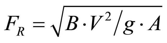
The shallow gradients associated with siphonic roof drainage systems mean that hydraulic jumps form readily when the inflow is supercritical [12].
An alternative approach to minimum system velocity is described:
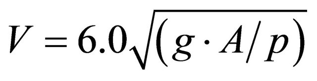
Essentially, if the flow velocity is too low, it will not be able to entrain air into the flow, or preclude bubbles rising to form air pockets along the pipe soffit. Within SRDS’s transient propagation occurs as an inevitable consequence of any change in the system operating condition. The magnitude of any pressure transient depends upon the properties of the fluid, conduit and the rate of change of the system conditions [15]. Theory suggests that the sudden blockage of a siphonic outlet, by detritus such as leaves, can lead to the generation of large pressure transients. Also the surcharge of the sewer can cut off the water path; in this situation flow may be rapidly brought to rest. In these conditions significant pressure transients are generated [16].
2.2. Single-Outlet Siphonic Roof Drainage
Air entering via reduced flow depths causes the severest problems, if a large pocket of air is drawn into the system, it can cause a sudden local de-pressurisation which then propagates through the entire system when it reaches the main vertical stack [11]. Due to the high negative pressures that can occur in SRDS’s, it is important that a resilient material is used with high resistance to implosion. In addition the system must be securely fixed with strong brackets to maintain their integrity through periods of vibration, which occur during both priming and at inflow rates between 40% and 100% of system capacity.
Increasing system capacity by 10% equates to an increase in the rainfall return period of 20% - 40%. Whilst allowing additional capacity is prudent, this reduces the frequency during which the SRDS’s is likely to operate in a fully primed state [12]. In order to prevent flooding at roof level, siphonic systems need to prime quickly and attain their design flow rate within the duration of the design storm event, BS8490:2007 suggests that it should take a maximum of 60 seconds to prime a system. However, other than for idealised installations, there is no analytical method available which can determine how long a system will take to prime, or even if a system will prime [12]. As analytical methods to allow the priming process to be considered in detail during the design phase, are not available, designers should use their understanding of the priming process to inform decisions. Current design practice assumes that, for a specified design storm, a siphonic system fills and primes rapidly with 100% water. This assumption allows siphonic systems to be designed utilizing steady state hydraulic theory [10].
2.3. Multi-Outlet Siphonic Roof Drainage
Frequently SRDS’s are installed in a system with more than one outlet connected to a single downpipe known as a multi-outlet system. Studies into the performance of multi-outlet SRDS’s broadly confirm that priming characteristics are similar to, though more complex, than the priming of a single outlet system. The most significant differences occur due to the inter-relationship between outlets, which create more complex flow conditions. This increases the occurrence of mixed water-air (two phases) flow in the system [1]. Indeed the problems encountered with SRDS’s are exacerbated when the system incorporates more than one outlet connected to a single downpipe.
A key benefit of installing a multi-outlet SRDS’s is their ability to redistribute flows between outlets if one becomes blocked [12]. BS8490:2007 suggests the return period used to determine the design rainfall intensity should be based upon the same categories of risk as described in BS EN 12056-3 for CRDS. It also suggests that SRDS’s are designed to cater for the steady-state flow conditions corresponding to the design rainfall intensity, with no allowance made for storage effects within either the gutters or the pipework. This approach neglects the small quantities of entrained air that enter a siphonic roof drainage system due to turbulent gutter conditions [11]. It has however been reported to yield characteristics similar to those observed in laboratory test rigs [10]. However, one European installer is known make allowance for two phase flow by using reduced flow density.
Bernoulli’s energy equation is used to determine the change in flow conditions between any two points in the system (BS8490:2007):

The terms on the right hand side of the equation indicate the changes in the total energy of the flow, attributable to the pressure energy, (h1 – h2), potential energy (z1 – z2) and the corresponding kinetic energy, where Point 1 is upstream of Point 2. The terms on the left hand side of the equation determine the loss of total energy between the two points. This accounts for the losses at bends, fittings, changes in cross-sectional area and pipe frictional losses.
BS8490:2007 suggests the use of the Colebrook-White relationship to calculate energy losses due to hydraulic resistance. However, these relationships are known to perform poorly in applications where the water contains air [17]:

This equation involves the pipe diameter, surface roughness and viscosity of the liquid. These two equations are applied across the whole piping network to obtain the SRDS’s design [18]. However, steady-state design methods are not applicable when a SRDS’s system is exposed to either a rainfall event below the design criteria, or an event of time-varying intensity. During these periods the flow may contain substantial quantities of air. As such events are the norm; it is clear that current design methods may not be suitable for determining the day-to-day performance characteristics of siphonic roof drainage systems. This is a major disadvantage, as it is during these events that the majority of operational problems (noise and vibration) tend to occur. There is also no published method to assess ability to prime.
3. Modulated Flow Siphon System
3.1. Development Procedure
The basic apparatus is illustrated schematically in Figure 1, and consists of a cap which is allowed to move vertically in response to prevailing suction pressure and flow
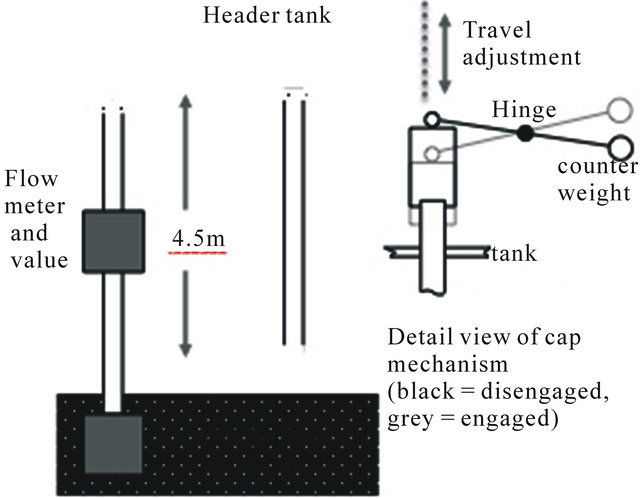
Figure 1. Schematic view of test apparatus showing water recirculation system between header tank and sump tank, and an expanded view of the cap system showing counterweight to adjust the ELAM, cap in upper, disengaged (black) and lower engaged (grey) positions, and travel limiter.
conditions at the SRD system inlet. Elementary laboratory experiments confirm the effectiveness of the concept and have provided basic sizing data.
The resting state of the mobile cap is in the upper “off” position, until siphonage starts, then the prevailing negative pressure in the pipe sucks the mobile cap down against the spring to the lower “on” position until the water level drops.
The resting, “off”, up position is achieved by simple mass balance. The mobile cap is fitted with guide vanes internally that prevent closure of the siphon and therefore water hammer. The mobile cap remains at the lower position until the siphon is broken, suddenly releasing the mobile cap to return to the “off” position. The key fact is that the water has been siphoned to a lower level than the starting position of the mobile cap, which effectively modulates the system, eliminating hunting and, therefore, noise. A floatation device was also added to minimize the effective mass of the system and reduce cycling time. Appropriate measures to prevent blockages by windblown debris will be developed and incorporated once live site trials are established. However, preliminary laboratory investigations indicate that the mobile cap provides some resistance to blockages. Such a system will cope with a wider range of rainfall intensities and will become more useful as climate change brings more diverse and intense storms to the UK and other locations.
No existing data was available for an SRD with a mobile cap therefore the following series of comparative tests were undertaken, involving the following parameters:
• The affect of changing the cap diameter;
• The affect of limiting the cap travel;
• The affect of adding a flotation device to the effort arm.
For each of these parameters, the maximum effort lever arm moment (ELAM) at which the cap would engage, and the minimum ELAM at which the cap would disengage were measured. These tests were completed for a range of flow rates, to determine the effect they hand on the system operation.
3.2. Apparatus
The following equipment was configured to carry out the above tests is shown schematically in Figure 1. This arrangement simulates a typical siphonic roof drainage system which drains a roof situated on top of a building envelope, and in turn discharges in free air into a below ground drainage system. The apparatus consisted of a high level drainage tank, siphonic drainage pipe system, feed tank, sump pump, feed pipework, flow meters and regulating valves. The drainage tank was use to represent a roof gutter whilst the sump pump and feed pipework was used to provide simulated rainfall into the drainage tank.
Regulating valves were used to control the flow of water into the drain tank and the flow rate was measured using an orifice plate flow meter capable of recording up to 3.6l s at ±0.1 l/s accuracy. The height difference between the tanks was 5 m, with an operating head available of 4.50 m. The simulated siphone pipe was 21 mm internal diameter, and three cap sizes of 35 mm, 40 mm, and 45 mm internal diameter (Caps 1, 2 and 3 respectively), all of 70 mm internal height, were used.
The drainage tank was used to simulate a typical roof gutter. The tank was fitted with a drainage pipe, feed pipe with baffle plate to minimize turbulence and overflow pipe. The feed pipe supplied water into the drainage tank below the water level, though a bell mouth inlet to limit turbulence in the tank. This ensured that flow into the siphonic drain pipe was weir flow at low tank inflow rates and orifice flow at high tank inflow rates. To disengage the siphonic cap when the tank had been drained a counter weight was added to the effort arm. The ELAM could then be adjusted by moving the counter weight along the effort arm and fixing it in position using the locking nuts.
The performances of three different caps were tested. The effect of cap volume was tested by using caps of differing diameter which had a constant cap height. These laboratory prototypes had a transparent top to enable the fluid flow to be observed. To ensure water could flow when the cap was fully engaged the caps are fitted with guide vanes which ensure the cap sits squarely above the crown of the drainpipe. A variety of counter weights were manufactured to produce the required ELAM to measure the maximum ELAM beyond which the cap would not engage, and the minimum ELAM below which the cap would not disengage for the various tests. The weights were sized to ensure the effort arm and the associated counter weight remained clear of the drain tank water at all times to prevent the ELAM being affected by buoyancy.
Figure 1 also shows the situation when a generalised cap was fully engaged, at this point the cap is drawn down until the cap sits on the crown of the drain pipe. A gap is maintained at all times above the siphon pipe by the lever arm design-this prevents full cap travel, maintains water flow and prevents water hammer. Figure 1 also demonstrates the disengaged situation, the top of the siphonic cap sits clear of the drain pipe, however, the lower rim of the cap does not rise above the top of the drain pipe. To measure the effect of reducing the travel of the engagement/disengagement of the system, a restrictor in the form of a simple threaded rod which prevented the cap from fully rising was placed above the load arm. This could be adjusted through the use of a locking nut. In this device, cap engagement/disengagement is roughly analogous to a conventional SRD priming/un-priming.
Floats were attached to the end of the counterweight to cause a greater disengage/engage operating range. The floats were manufactured from closed cell polystyrene to ensure they would not absorb water when submerged. With the cap disengaged the floatation device is entirely submerged within the drain tank water. In this position it displaces its own volume in water. As water is denser than polystyrene the floatation device, whilst submerged, creates an upward force on the effort arm which resists the downward force created by the counter weight.
4. Results
4.1. General Procedure
Altering the cap diameter, cap travel and the presence of a float was shown to affect the maximum ELAM against which the system would engage, and the minimum ELAM against which it would disengage. Analysis of these results provides the basis for design optimization. Comparison of the cap system to a siphon with no cap indicates a wider rTS operating range.
The processes and system characteristics such as water inflow rate range were identical for each test.
4.2. Cap Engagement (System Priming)
The general experimental procedure for establishing the system performance during cap engagement was straightforward: the water inflow rate was increased in steps until the inflow rate was beyond the siphon capacity of the system, for a range of ELAM applied force values, and for three cap sizes. Figure 2 shows the results. For each step, the time taken for the cap to engage (i.e. system to prime) was recorded. In every case where cap priming occurred, the operation of the cap was broadly the same, differing only in the time taken to
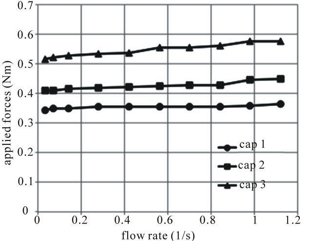
Figure 2. Cap engagement (priming) performance with a range of applied ELAM forces and water inflow rates, for the three caps used.
prime. The drain tank water level rose until flow occurred; the cap remained in the de-primed position until siphonage started, priming the cap. If the tank water level fell below the base of the cap, air would be admitted and the cap would de-prime. When this occurred the test was repeated with a reduced ELAM. The maximum ELAM occurred when the water level reached the base of the de-primed cap, and the cap primed without admitting air into the system. Below the system capacity the cap primed, at the maximum ELAM, followed this pattern irrespective of the inflow rates. As the inflow rate increased the cap would prime against a greater ELAM. This may be attributed to the longer period taken at high inflow rates, for the tank to drain to the base of the cap. This may allow more air to be purged from the downpipe, thus increasing system depressurisation.
The balance between whether the siphon breaks or the cap engages was a function of the ELAM and the resulting balance of forces. The contribution of force experienced due to the surface tension was calculated as 0.001732 Nm, whilst the ELAM attributable to the empty cap and load arm self weight was calculated as 0.140 Nm. The magnitude of the force attributable to surface tension did not form a significant part of the system, and was ignored.
With a low ELAM, the cap would prime once the water level had reached the crown of the drainpipe. Water initially entered the drainpipe via weir flow, this led to annual flow in the downpipe; the friction between this water flow and the surrounding air-core produced a negative pressure in the downpipe. This occurred in a similar pattern to the generation of negative pressure transients in building waste water drainage systems. These negative pressures led to increased flow being drawn in to the drain pipe, as a result of full bore flow developed and all air was expelled from the downpipe. This increased the siphon pressure sufficiently to engage the cap, when this occurred the remaining air pocket within the crown of the cap was entrained in the outflow. The cap then rested on the crown of the drainpipe. The air pocket was then expelled from the base of the drainpipe and the system was fully primed and working at capacity. With a high ELAM and low water inflow rates the cap would not prime, effectively turning the system into a conventional SRDS, resulting in hunting and noisy, two-phase flow. At higher inflow rates above the system capacity, the cap would sometimes be seen to prime, but flow modulation was absent and an overflow situation was evident.
4.3. Cap Disengagement (System De-Priming)
Cap disengagement (i.e. de-priming) was investigated in a similar process to priming and a range of water flow rates, cap sizes and ELAM’s were employed. Figure 3

Figure 3. Cap dis-engagement (de-priming) performance with a range of applied ELAM forces and water inflow rates, for the three caps used.
shows the results. For each inflow rate tested the minimum ELAM, below which the cap would not de-prime, was recorded. The process of cap de-priming at this ELAM was quite straightforward: the drain tank water level fell from initially being slightly higher than the crown of the drain pipe to the base of the primed cap, admitting air, and breaking the siphon thereby causing de-priming.
For the purposes of this investigation, cap de-priming was investigated by forcing priming at a particular flow rate by physically holding the cap down, then releasing it to the control of the prevailing forces. When the water inflow rate was too low or the ELAM too high, depriming was instantaneous.
Predictably, with a relatively low ELAM a point could be found where the air ingestion rate was just sufficient to slow the rate of water loss due to siphonage: this caused cycling of the water level in the range of a few millimetres and was taken to be the equivalent of hunting in this system, although noise was not evident.
Cap dis-engagement (de-priming) performance with a range of applied ELAM forces and water inflow rates, for the three caps used.
4.4. Cap Travel Limitation
The processes through which cap priming and de-priming were investigated when the cap travel was restricted were broadly similar to those above. The test was restricted to cap number 2. However the actual results recorded differed significantly. Restricting the cap travel reduced the volume of air in the crown of the cap thus increasing the mass of water in the cap during priming. This had the effect of decreasing the available effective ELAM; as such the system would prime against a greater actual ELAM. The different degrees of restriction against the normal travel of 60 mm are shown in Figure 4. Only cap priming is shown, which is justified as there was no

Figure 4. Effect of limiting cap travel on cap engagement (priming) performance with various height limits from no restriction up to 40 mm (approximately 75% of available travel) and range of applied ELAM forces and water inflow rates, for Cap 2 only.
effect on cap de-priming: cap movement restriction simply reduced the cycle time.
4.5. Float
The procedure for investigating the effectiveness of the float was similar to that employed above. The test was restricted to cap number 2. When a float was attached to the effort arm the ELAM force generated was dependent on the water level. With the cap in the de-primed position the float was fully submerged, the difference in density between the float material and the tank water generated an up-force which opposed the down-force of the counter weight, thus reducing the effective down-force.
The up-force generated was directly proportional to the float volume. The additional up-force from the float would only be experienced as the water level was rising and the cap was un-primed: after priming, the cap would be pulled down and the float would be lifted clear of the water. The data is representative of the ELAM present during priming. This approach is justified as the depriming state is of no operational significance as the float is clear of the water.
From Figure 5, Floats 1 (25% displacement mass) and 2 (50% displacement mass) experienced a relatively modest increase in the maximum ELAM as the inflow rate increased; this is similar to the results without a float. Float 3 (75% displacement mass) experienced a more significant increase in the maximum ELAM as the inflow rate increased. This was due to the greater float volume which caused partial cap engagement; this partial engagement had the effect of increasing the water volume in the cap. This additional water volume reduced the effective ELAM as described above.
The mass of the float and its associated components increased the ELAM during disengagement, however the impact was considered marginal due to the very low density of the styrene used. The addition of any float had an effect on the time taken for the cap to fully drop to the operating position during priming, as shown in Figure 6,

Figure 5. Effect of adding various float sizes, expressed as a percentage of the ELAM mass, on cap engagement (priming) performance for a range of applied ELAM forces and water inflow rates, for Cap 2 only.
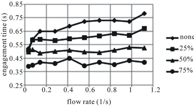
Figure 6. Effect of adding various float sizes, expressed as a percentage of ELAM mass, on cap engagement time for various applied ELAM forces and water inflow rates, for Cap 2 only.
with larger float size reducing the time required. This result could not be achieved by reducing the ELAM without adversely affecting disengagement performance.
Figure 7 compares the engaging/disengaging (priming/de-priming) cycle time of a system fitted with Cap 2, to a system with no cap fitted at all. A logarithmic vertical scale was used for clarity, due to the range of cycle times recorded for the system with no cap, which is essentially a conventional siphonic system. Note that for low flow rates, the first three data points for the uncapped system are absent as the system would not prime at all, simply hunting between plug and open channel flow. From Figure 7 it is clear that the rTS range of a capped system is increased and modulation is apparent (thereby reducing noise and vibration) markedly compared to an uncapped system.
4.6. Effective Working Zones
From Figure 2, it can be seen that above the maximum ELAM force line for each cap, a cap will not prime irespective of tank inflow rate. From Figure 3, it can be seen that a cap will not de-prime, and so rise, below the minimum de-prime ELAM. By redrawing Figures 2 and 3 and combining them, Figure 8, it can be seen that ef-

Figure 7. Comparison of engage/disengage (prime/de-prime) cycle times between capped and uncapped siphon systems for a range of water inflow rates. Error bars refer to ranges of results taken over 5 repeats due to large variability observed.
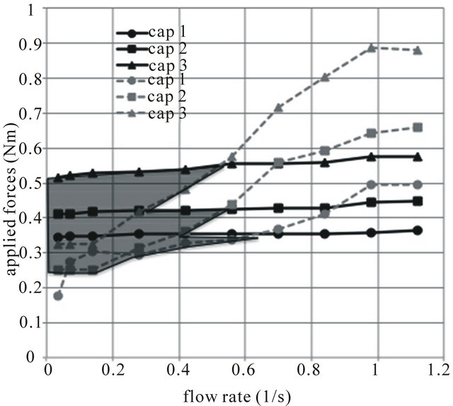
Figure 8. Suggested operating range of laboratory prototype, indicating wider rTS range than previously available.
fective working envelope suggests an operating envelope analogous to that of a fan.
Within this envelope the cap will both engage and disengage satisfactorily. This modulates the flow, creating an effective siphonic drainage system which primes and depressurises rapidly for rainfall events below system capacity. Within the effective working zone the cap minimises the duration of pressure transients and effectively reduces the associated noise and vibration. This represents an rTS range of approximately 6 and is a greater operating envelope than that of a conventional SRDS with a single rTS value.
5. Conclusion
For each test it was found that the force attributable to surface tension did not form a significant part of the process. The force attributable to the empty cap and load arm self weight was constant therefore the significant variable was the remaining force, attributable to the sharply negative pressure caused by siphonic flow or the modifications caused by the stroke limiter or float. In the engaged position the reduction in water level (at the minimum ELAM required to disengage the cap) is the full height of the cap. In the disengaged position the increase in water level is limited to the difference in height between the base of the disengaged cap and the crown of the drain pipe. The empirical data gathered on the parameters measured can be used as a design aid to ensure that the cap will engage and disengage across a wider range of inflow rates, and therefore rTS values, than current SRDS’s. This research has also demonstrated that these aims may conflict which limits the useful working zone of a mobile cap. To ensure the system engages at all flow rates the lowest ELAM, which occurs at the lowest inflow rate, should be selected. No safety margin is deemed to be necessary in the event that the cap fails to engage as the system simply operates as a normal SRDS.
REFERENCES
- G. B. Wright, L. B. Jack and J. A. Swaffield, “Investigation and Numerical Modelling of Roof Drainage Systems under Extreme Events,” Building and Environment, Vol. 41, No. 2, 2006, pp. 126-135. doi:10.1016/j.buildenv.2004.12.006
- D. Langdon, “Spon’s Architects’ and Builders’ Price Book 2009,” 134th Edition, TJ International Ltd., Padstow, 2009.
- J. T. Houghton, L. G. Meira Filho, D. J. Griggs and K. Maskell, “An Introduction to Simple Climate Models Used in the IPCC Second Assessment Report—IPCC Technical Paper II,” IPCC, Geneva, 1997. http://www.ipcc.ch/pdf/technical-papers/paper-II-en.pdf
- R. T. Watson and the Core Writing Team, “IPCC Third Assessment Report: Climate Change 2001: Synthesis Report,” IPCC, Geneva, 2001. http://www.grida.no/publications/other/ipcc_tar/?src=/climate/ipcc_tar/
- R. W. P. May, “Design Criteria for Siphonic Roof Drainage Systems, Report SR654,” HR Wallingford Ltd., England, 2004.
- R. Gargano and W. H. Hager, “Undular Hydraulic Jumps in Circular Conduits,” Journal of Hydraulic Engineering, Vol. 128, No. 11, 2002, pp. 1008-1013. doi:10.1061/(ASCE)0733-9429(2002)128:11(1008)
- G. B. Wright, J. A. Swaffield and S. Arthur, “Investigation into the Performance Characteristics of Multioutlet Siphonic Rainwater Systems,” Building Services Engineering Research & Technology, Vol. 23, No. 3, 2002, pp. 127-141. doi:10.1191/0143624402br041oa
- Arthur, et al., “Operational Performance of Siphonic Roof Drainage Systems,” Building & Environment, Vol. 40, No. 6, 2005, pp. 788-796.
- S. Arthur and J. A. Swaffield, “Siphonic Roof Drainage: Current Understanding,” Urban Water, Vol. 3, No. 1-2, 2001, pp. 43-52. doi:10.1016/S1462-0758(01)00021-8
- S. Arthur and J. A. Swaffield, “Siphonic Roof Drainage: The State of the Art,” Urban Water, Vol. 3, No. 1, 2001, pp. 43-52.
- S. Arthur and G. B. Wright, “Recent and Future Advances in Roof Drainage Design and Performance,” Building Service Engineering Research and Technology, Vol. 26, No. 4, 2005, pp. 337-348.
- S. Arthur and J. A. Swaffield, “Siphonic Roof Drainage System Analysis Utilising Unsteady Flow Theory,” Building and Environment, Vol. 36, No. 8, 2001, pp. 939-948. doi:10.1016/S0360-1323(00)00049-4
- S. Arthur and G. B. Wright, “Siphonic Roof Drainage Systems—Priming Focused Design,” Building and Environment, Vol. 42, No. 6, 2007, pp. 2421-2431. doi:10.1016/j.buildenv.2006.08.021
- G. B. Wallis, “One-Dimensional Two-Phase Flow,” McGraw and Hill, New York, 1969.
- D. J. Acheson, “Elementary Fluid Dynamics,” Oxford University Press, New York, 1990.
- J. A. Swaffield, J. Ballanco, J. A. McDougall, “Pressure Surge in Building Utility Services Exacerbated by the Presence of Trapped or Entrained Air,” Building Service Engineering Research and Technology, Vol. 23, No. 3, 2002, pp. 179-196.
- BS EN 12056-3:2000, “Gravity Drainage Systems Inside Buildings. Roof Drainage, Layout and Calculation,” British Standards Publishing Limited (BSPL), 2000.
- I. E. Idelchik, “Handbook of Hydraulic Resistance,” 3rd Edition, Jaico Publishing, Mumbai, 2007.