Journal of Crystallization Process and Technology
Vol. 2 No. 4 (2012) , Article ID: 23430 , 6 pages DOI:10.4236/jcpt.2012.24024
Fourier Transforms of Tubular Objects with Spiral Structures
![]()
Indian Association for the Cultivation of Science, Jadavpur, India.
Email: gbmitra@gmail.com
Received May 5th, 2012; revised June 8th, 2012; accepted July 3rd, 2012
Keywords: Crystal Structure; Minerals; Deformities; Spiraling; X-Ray Diffraction
ABSTRACT
Crystal structures of several naturally occurring minerals are known to contain various deformities such as cones, cylinders, and tapered hollow cylinders with different apex angles, which have been described as solid and hollow cones, “cups”, “lampshades” as well as rolled cylindrical planes. The present study was undertaken to determine how these different shapes within a crystal structure can be explained. Since the usual method of observing them is by either X-ray and electron diffraction or electron microscopy, we investigated Fourier transforms of these forms, which were considered in terms of spirals with varying radii. Three types of spirals were considered, namely: 1) Archimedean spiral; 2) Involute of a circle or power spiral and 3) Logarithmic spiral. Spiraling caused the radius r to be modified by a factor f(θ), so that r becomes rf(θ), where f(θ) = θ for Archimedean helix, θn for power helices like θ1/2 for Fermat’s helix, θ–1 for hyperbolic helix and eθ or e–θ for logarithmic helix, r and θ being co-ordinates of the map on which the helix has to be drawn, f(θ) is unaffected by the magnitude of r. Expressions have been derived that explain the diffraction of structures containing the distortions described above, and bring all of these phenomena under one “umbrella” of a comprehensive theory.
1. Introduction
Even in the early days of the study of minerals by electron microscopes, it was realized that minerals like chrysolite and halloysite shows additional cylindrical structures with spirals [1]. Jagodzinski and Kunze [2-4] also observed this phenomenon, which was confirmed by Honzo and Mihama [5] who observed small fragments of Halloysite under electron microscope and found that they were wrapped with spirals of tubular stacks. According to Waser [6], these sheets were formed by bending and twisting three-dimensional crystallite into curvaceous shapes. Similar was the observation of Whittaker [7] who found that the spirals were of the type of involutes of circles. The spirals were also mentioned by Waser [6] although his calculations were on the basis of parallel coaxial tubes. Conventional theory utilize parallel coaxial tube model confirmed by the observation of Haanstra [8] and Sumio Iijima [9] that carbon tubules are formed by coaxial carbon sheets, helically rolled up. However, later discovery of graphitic cones and boron nitride cones [10-13] showed that instead of parallel cylinders, there may occur coaxially rolled-up cylinders, as well as tapering cylinders, sometimes ending into sharp cones, sometimes into hollow tapering cylinders, and sometimes end ing into various angles. The various forms assumed by nanotubes include isolated cones [12], disordered aggregates of cones [10], multilayered cones with different apex angles [14,15], as well as stacked closed cones, also called stacked lampshades. Among naturally occurring minerals, Halloysite [16], Cylindrite [17], tochilinites [18] etc form cylindrical morphology. The cylindrical morphology of terrestrial Tectialinite has been described by Jambor [19] as resembling a rolled up newspaper.
The aim of the present paper is to determine how the different shapes can be explained. Since the usual method of observing them is by either X-ray and electron diffraction or electron microscopy, as the first essential step to be considered, we investigate Fourier transforms of the various forms.
2. Preliminary Considerations
Spirals can, in preliminary considerations be of two types—two dimensional or three dimensional. For two dimensional helices, it may be mentioned that it is a curved arc which refuses to close—contrary to a circle which closes. A circle is a two-dimensional curve, every point on which is equidistant from the center. Hence, if one starts from any point on the circular path in the same direction and continues in that direction, one will finally arrive in the same point from where one started. Mathematically, the operation is given by a sin 2πr or a cos 2πr, and is described by the equations  and
and  , so that
  .
.
However, if there is a distortion on a circle, which prevents a point moving on a given circle from returning to the same point on this circle or the sphere on completing one turn of each circle—either by increasing or decreasing the radius of the circle at that point—the circle is said to have been spiraled. Thus, spiraling results from a change in the magnitude of the radius by a factor f(θ), where θ is the angle by which the particle moves on the arc of the spiral.
Similar considerations are valid for an ellipse. There, the ellipse represented by  and
and  will be spiraled as
  and
and  and every point on the ellipse will change with every value of θ. Similarly, there can be three dimensional spirals—spherical, spheroidal, elliptical, ellipsoidal, cylindrical, etc. where, say, x and y are functions of z or vice versa. For example,
 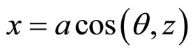 ,
,  , z = z represents a circular, cylindrical helix.
In the present case under consideration, solid and hollow rods, solid and hollow cones, as well as solid and hollow tapering cylinders ending into different apex angles—can all be treated as two-dimensional problems and hence involving two-dimensional helices. Vigodsky [20] had categorized three types of two-dimensional helices, involving three main types of spirals, namely: 1) Archimedean spiral; 2) Involute of a circle or power spiral and 3) Logarithmic spiral. Ferris [21] had later given mathematical expression for these three types of spirals as follows:
1) The Archimedean spiral:

a being constant independent of r and θ. The curve is described in terms of polar coordinates r and θ.
2) The power spiral:

a and n are constants independent of r and θ, the polar coordinates of the term, n constant—either positive or negative.
3) The Logarithmic Spiral:

a constant as above, and e the base of Napierian logarithm. In all the three cases, θ can be positive or negative.
Here, we will determine how the different shapes within a crystal structure can be explained. Since the usual method of observing them is by either X-ray and electron diffraction or electron microscopy, as the first essential step to be considered, we investigate Fourier transforms of the various forms. The optimum Fourier transform of a general spiral structure should be able to explain the growth and formation of almost all crystalline objects.
3. Theory
3.1. Fourier Transform of a Solid Circular Cylinder
Let the solid circular cylinder of radius r and length l be described by the equation  and the corresponding reciprocal lattice is given by

The corresponding Fourier transform of the cylinder is given by
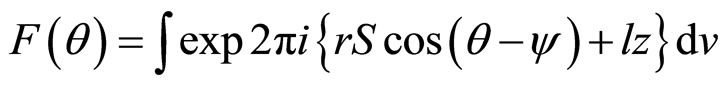 (1)
(1)
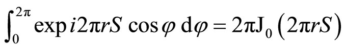
It is known that
 (2)
(2)
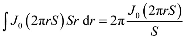
so that
 (3)
(3)
Thus

neglecting the term in z.
 (4)
(4)
Now, it is known that
 (5)
(5)
Putting m = 0

 (6)
(6)
3.2. Fourier Transform of a Hollow Circular Cylinder
Let the hollow circular cylinder have external and internal radii r1 and r2, respectively. Proceeding as in the previous case, we have
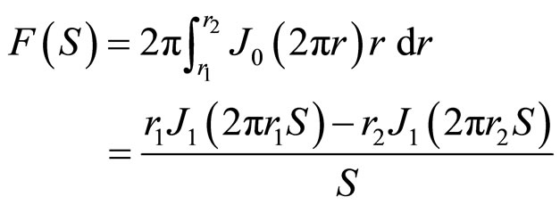 (7)
(7)
Equations (6) and (7) are the same as in Oster and Riley [22].
3.3. Fourier Transform of a Solid Cylindrical Cone
In Figure 1, let the cone have a radius r, height H and apex angle 2φ. So the radius changes from 0 at the apex to r at the base. Note:

So, according to equation (4)

where 
Hence
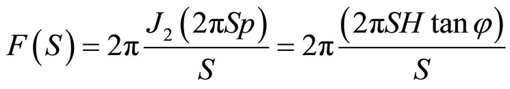 (8)
(8)
3.4. Fourier Transform of a Hollow Cone
The hollow cone may be of two kinds. It may be pointed—i.e. the outer cone may end at an apex point O whose height from the base of the cone is H and the apex angle is 2φ, while for the inner cone, the apex angle is 2ω, the height remaining the same. In Figure 2, the outer radius r1 of equation (7) is H tan φ and the inner radius, the radius r2 of equation (7) is H tan ω. For this case,
 (9)
(9)
The hollow cone may be truncated at a height (H − h) above the base of the cone. In this case, the equation (9) will be modified by replacing H by (H − h). Other similar shapes can easily be considered in the light of the above discussions.

Figure 1. Diagrammatic representation of a solid cone of height H and apex angle 2φ.

Figure 2. Diagrammatic representation of a hollow cone with the outer cone ending at an apex point O whose height from the base of the cone is H and the apex angle is 2φ, while for the inner cone, the apex angle is 2ω, the height remaining the same. Alternately, the hollow cone may be truncated at a height (H − h) above the base of the cone.
3.5. Effect of Spiraling on Fourier Transform
We have described in equations (6)-(9) the Fourier transforms of solid circular cylinders, hollow circular cyliders, solid and hollow cones, both tapered and pointed end. These are the shapes and sizes of carbon and boron nitride inclusions in carbon dusts as observed under elecztron microscope. Now let us consider what happens when these are spiraled. Spiraling causes the radius r to be modified by a factor , so that r becomes
 , where
  = θ for Archimedean helix, θn for power helices like θ1/2 for Fermat’s helix, θ−1 for hyperbolic helix and eθ or e−θ for logarithmic helix, r and θ being co-ordinates of the map on which the helix has to be drawn,
  is unaffected by the magnitude of r.
Thus, in Equation (6), r, in equation (7), r1 and r2, in Equations (8) and (9), H will be affected by the spiraling effect.
Solid circular cylinder,
 (10)
(10)
Hollow circular cylinders
 (11)
(11)
For solid cylindrical cones,
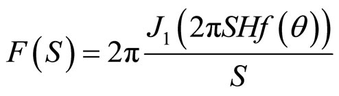 (12)
(12)
And for hollow cylindrical cones
 (13)
(13)
4. Discussions
A weathering environment can cause secondary crystalline structures in minerals either through alterations in the primary structure or through precipitation of a soluble species [23]. Clay minerals including kaolinite and halloysite are particularly susceptible to this sort of weathering, which leads to distortions in the original structure. Kaolinite and halloysite are 1:1 dioctahedral phyllosilicates with the difference that halloysite structure contains H2O molecules in the interlayer (Al2Si2O5(OH)4∙2H2O) [23] Unlike kaolinite, which is planar, halloysite is observed in tubular or rolled structures, which is believed to relieve structural strains that arise as a result of a misfit between octahedral and tetrahedral sheets. Trioctahedral chrysolite has a similar structure (Mg3(Si2O5)(OH)4), except that it curls in the opposite direction due to the smaller dimension of the Al3+ octahedron in halloysite relative to the Mg2+ octahedron in chrysolite. Early electron micrographic studies revealed the presence of secondary structures in these minerals, describing halloysite to consist of hollow rods or rolled sheets 10 - 15 µm in length, with numerous examples of rolls within rolls [1]. Electron micrographs and diffraction diagrams of chrysolite revealed a tubular form of rolled sheet crystal as well [5]. Jagodzinski and Kunze found evidence of a helical and spiral structures in chrysolite, that may be described in terms of radial and axial dislocations [3].
Other structures have also been found in crystal morphologies. During the deposition of carbon by pyrolysis of carbon monoxide above 1800˚C, a columnar growth of carbon could be induced by β-SiC crystals which could be visualized as stacked from parallel layers of carbon atoms in a hexagonal graphite network bent into a cone mantle with a top angle of about 141˚C [8]. Sumio Iijima reported the preparation of finite carbon structures, similar to fullerenes, consisting of needle like tubes, comprising of coaxial tubes of graphitic sheets where the carbon-atom hexagons are arranged in a helical fashion about the needle axis [9]. Later studies generated nanometer-sized carbon cones by vapor condensation of carbon atoms on a graphite substrate [10], while others reported generation of carbon structures consisting of graphitic microstructures with total disinclinations that are multiples of +60˚, due to the presence of pentagons within the hexagonal structure, resulting in the formation of carbon cones [11], or horn-shaped sheaths of single walled graphene sheets [12]. Graphite nano and microcones were found in the pores of commercial glassy carbon, growing along with cylindrical multiwalled nanotubes and graphite polyhedral crystals [14]. Tubular graphite cones synthesized using a chemical vapor deposition method were found to be composed of cylindrical graphite sheets; a continuous shortening of the graphite layers from the interior to the exterior makes them cone shaped [15]. Other structures that have been described include stacked closed cones (stacked cups), stacked open cones (stacked lampshades) and cone-helix structures (see [24] and references therein).
The secondary structures were found not only in carbon particles but also in other compounds such as boron nitride which consist of an ordered stacking of seamless conical shells [13]. Cylindrite, a lead, tin, antimony and iron sulfosalt, contains two types of sheets: hexagonal and tetragonal, with the structure changing systematically from the core to the periphery of the crystals. At the core, the sheets are parallel to each other whereas further from the core, the sheets diverge giving rise to cylindrical structures [17]. Similarly, the dominant morphology for tochilinites (1 Fe0.9S.1.67 [(Mg,Fe)(OH)2]) are filled and hollow cylinders [18], which has also been described as a rolled-up newspaper [19].
Multiple investigators have attempted to explain the secondary structures by X-ray diffraction studies and its mathematical analysis. Early studies, as exemplified by the theoretical discussion set forth by Waser [6] studied Fourier transforms and scattering intensities of discrete tubular objects as well as concentric cylinders, but failed to take into account the spiral cylinders that were observed as well. Many studies discussed the X-ray diffraction phenomena to be expected from a tubular structure in which the wall consists of a succession of equally spaced layers mutually ordered in the direction parallel to the cylinder axis [2-4,7], however, till now, no comprehensive study that takes into consideration all the different types of structures has been effectively conducted. The majority of studies reported in the literature take into consideration the parallel coaxial tube model popularized by Waser [6]. However, molecular modeling and structural analyses compared to reported experimental observations showed that neither parallel coaxial tubes nor stacked cone models could explain the wide variety of apex angles observed for nanofibers and related structures [24]. One the other hand, cone-helix models allowed for a variety of apex angle structures and were applicable for nanofibers [24].
In 1975, we had attempted to explain the structure of halloysite [16] in the light of a theory of diffraction by curved crystals developed by us [25-27]. It was concluded that metahalloysite had a lath-like cylindrival structure and the kaolin layers were considered to be arranged parallel to one another but shifted parallel to themselves [16]. Although the values of the lattice parameters were satisfactory, recent identifications of the secondary structures have rendered necessary the development of a theory which would explain not only perfect cylinders or coaxial cylinders but also helical and spiral structures. The special case of the theory of diffraction at small angles of scattering by a cylindrically constructed structure has recently been developed and general expressions for 2 and 3 dimensional cylindrically curved crystallites have been obtained [28]. The aim of the present paper was to extend these calculations to the conditions of helices and spirals which would explain the diffraction of structures containing the distortions described above, and to bring all of these phenomena under one “umbrella” of a comprehensive theory. This has been achieved in equations (10)-(13) which show the specific cases of equations (6)-(9) when the radius of the circle is variable.
In summary, in this paper, various types of spiral structures have been defined and classified—and their effect on tubular objects in the form of Fourier Transforms have been discussed. The observation under electron microscopes and similar devices of cones, cylinders, tapered hollow cylinders with various apex angles specifically in the cases of carbon and boron nitride powders have been explained.
5. Acknowledgements
The author expresses his deep sense of gratitude to Dr. Paramita Ghosh of University of California at Davis for encouragement and help in many ways. Sincere thanks are due to Bishwajit Halder for secretarial help.
REFERENCES
- M. S. Taggart Jr., W. O. Milligan and H. P. Studer, “Electron Micrographic Studies of Clays,” Clays and Clay Minerals, Vol. 3, No. 1, 1954, pp. 31-95. doi:10.1346/CCMN.1954.0030104
- H. Jagodzinski and G. Kunze, “The Rolled Structure of Chrysotile. II. Far Winklen Interferences,” Neues Jahrb. Mineral Monatsh, Vol. 6, 1954, pp. 113-130.
- H. Jagodzinski and G. Kunze, “The Rolled Structure of Chrysotile. III. The Manner of Growth of the Rolls,” Neues Jahrb. Mineral Monatsh, Vol. 7, 1954, pp. 137-150.
- H. Jagodzinski and G. Kunze, “Die Rcillchenstruktur des Chrysotils. I. Allgemeine Beugungtheorie und Kleinwinkelstreung,” Neues Jahrb. Mineral Monatsh, Vol. 10, 1954, pp. 219-240.
- G. Honzo and K. Mihama, “A Study of Clay Minerals by Electron-Diffraction Diagrams Due to Individual Crystallites,” Acta Crystallographica, Vol. 7, No. 6-7, 1954, pp. 511-513.
- J. Waser, “Fourier Transforms and Scattering Intensities of Tubular Objects,” Acta Crystallographica, Vol. 8, No. 3, 1955, pp. 142-150. doi:10.1107/S0365110X55000583
- E. Whittaker, “A Classification of Cylindrical Lattices,” Acta Crystallographica, Vol. 8, No. 9, 1955, pp. 571-574. doi:10.1107/S0365110X55001771
- H. B. Haanstra, W. F. Knippenberg and G. Verspui, “Columnar Growth of Carbon,” Journal of Crystal Growth, Vol. 16, No. 1, 1972, pp. 71-79. doi:10.1016/0022-0248(72)90091-7
- S. Iijima, “Helical Microtubules of Graphitic Carbon,” Nature, Vol. 354, No. 6348, 1991, pp. 56-58. doi:10.1038/354056a0
- M. Ge and K. Sattler, “Observation of Fullerene Cones,” Chemical Physics Letters, Vol. 220, No. 3-5, 1994, pp. 192-196. doi:10.1016/0009-2614(94)00167-7
- A. Krishnan, E. Dujardin, M. M. J. Treacy, et al., “Graphitic cones and the Nucleation of Curved Carbon Surfaces,” Nature, Vol. 388, No. 6641, 1997, pp. 451-454. doi:10.1038/41284
- S. Iijima, M. Yudasaka, R. Yamada, et al., “Nano-Aggregates of Single-Walled Graphitic Carbon Nano-Horns,” Chemical Physics Letters, Vol. 309, No. 3-4, 1999, pp. 165-170. doi:10.1016/S0009-2614(99)00642-9
- L. Bourgeois, Y. Bando, W. Q. Han, et al., “Structure of Boron Nitride Nanoscale Cones: Ordered Stacking of 240 and 300 Disclinations,” Physical Review B, Vol. 61, No. 11, 2000, pp. 7686-7691. doi:10.1103/PhysRevB.61.7686
- Y. Gogotsi, S. Dimovski and J. A. Libera, “Conical Crystals of Graphite,” Carbon, Vol. 40, No. 12, 2002, pp. 2263-2267. doi:10.1016/S0008-6223(02)00067-2
- G. Zhang, X. Jiang and E. Wang, “Tubular Graphite Cones,” Science, Vol. 300, No. 5618, 2003, pp. 472-474. doi:10.1126/science.1082264
- G. B. Mitra and S. Bhattacherjee, “The Structure of Halloysite,” Acta Crystallographica Section B, Vol. 31, No. 12, 1975, pp. 2851-2857. doi:10.1107/S0567740875009041
- S. Wang and P. R. Buseck, “Cylindrite: The Relation between Its Cylindrical Shape and Modulated Structure,” American Mineralogist, Vol. 77, No. 7-8, 1992, pp. 758-764.
- M. E. Zolensky and I. D. R. Mackinnon, “Microstructures of Cylindrical Tochilinites,” American Mineralogist, Vol. 71, 1986, pp. 1201-1209.
- J. L. Jambor, “New Occurences of the Hybrid Sulphide Tochilinite,” Geological Survey of Canada Paper, Vol. 76, No. 1B, 1976, pp. 65-69.
- M. Vigodsky, “Mathematical Handbook—Higher Mathematics,” 1975, Mir Publishers, Moscow.
- T. L. J. Ferris, A. Nafalski and M. Saghafifar, “Matching Observed Spiral Form Curves to Equations of Spirals in 2-D Images,” In: H. Tsuboi and I. Sebestyen, Eds., A pplied Electromagnetics and Computational Technology, IOS Press, Amsterdam, 2001, pp. 151-158.
- G. Oster and D. P. Riley, “Scattering from Cylindrically Symmetric Systems,” Acta Crystallographica, Vol. 5, No. 2, 1952, pp. 272-276. doi:10.1107/S0365110X5200071X
- M. E. Essington, “Soil and Water Chemistry: An Integrative Approach,” CRC Press, Boca Raton, 2004, p. 440.
- B. Eksioglu and A. Nadarajah, “Structural Analysis of Conical Carbon Nanofibers,” Carbon, Vol. 44, No. 2, 2006, pp. 360-373. doi:10.1016/j.carbon.2005.07.007
- G. Mitra, “Diffraction Intensities from a Cluster of Curved Crystallites. I. General Theory for Oneand TwoDimensional Cases,” Acta Crystallographica, Vol. 18, No. 3, 1965, pp. 464-467. doi:10.1107/S0365110X65001020
- G. B. Mitra and S. Bhattacherjee, “Diffraction Intensities from a Cluster of Curved Crystallites. II. The Effect of Curvature,” Acta Crystallographica Section A, Vol. 24, No. 2, 1968, pp. 266-269. doi:10.1107/S0567739468000422
- G. B. Mitra and S. Bhattacherjee, “Diffraction Intensities from a Cluster of Curved Crystallites. III. The ThreeDimensional Case,” Acta Crystallographica Section A, Vol. 27, No. 1, 1971, pp. 22-28. doi:10.1107/S0567739471000056
- G. Mitra, “Low-Angle Scattering by Cylindrical Structures,” Acta Crystallographica Section A, Vol. 66, No. 1, 2010, pp. 93-97. doi:10.1107/S0108767309044791
NOTES
*Current Address: 284B, Rash Behari Avenue, Kolkata, West Bengal, INDIA Previously: Professor and Head, Department of Physics, Indian Institute of Technology, Kharagpur.