R. Q. PEDRO ET AL.
566
steel screens, a honeycomb and a bellmouth at the begin-
ning of the settling chamber, as can be seen in [1]. The
aim of this work is to present the modifications of the
wind tunnel and, the preliminary flow evaluation of the
LABINTHAP wind tunnel with the contraction nozzle
only by means of velocity and turbulence profiles and,
effect walls.
2. Methodology
2.1. Wind Tunnel Modifications
Modifications proposed to improve flow quality in the
wind tunnel test section are in accordance with the pa-
pers developed by Bradshaw P. and Pankhurst R. C.,
1964 [3] and Metha R. D. and Bradshaw P., 1979 [4].
2.2. Screens and Honeycombs
Screens objectives are reducing the velocity fluctuations
in axial direction and making the velocity profile more
uniform by a static pressure drop. Reference [3] sug-
gested use four screens with an open area ratio of β >
0.57 and the distance between screens have to be of 500
dw (wire diameters). Reference [4] suggested that the
distance between the last screen and the contraction inlet
has to be about 0.2 diameters of the settling chamber.
According to previous criterions, five stainless steel
screens of 20 meshes will be installed in the wind tunnel
settling chamber, wire diameter of 0.23 mm and an open
area ratio of 0.67. The distance between the last screen
and the contraction will be of 500 mm and, the separa-
tions between screens will be of 120 mm (521 dw).
Honeycombs are effective to remove swirl and lateral
mean velocity variations, as long as the flow yaw angles
are not greater than 10˚ [5]. The design parameters for
honeycomb are length to diameter ratio and porosity. The
cell length should be about 6 to 8 times its diameter, as
mentioned in [4]. The honeycomb that will be installed
in the wind tunnel settling chamber will have a cell
size of 10.5 mm, thickness of 0.2 mm and a length of 85
mm.
2.3. Contraction Nozzle and Bellmouth
The purposes of contraction nozzle are: a) to increase the
mean velocity, b) to reduce velocity variations and c) to
reduce velocity fluctuations. The recommended area ra-
tios of the contraction nozzle to get these criterions are 6
to 9, as mentioned in [4]. The method used to design the
contraction nozzle was the one suggested by Morel T.,
1977 [6], this method considered an incompressible and
no viscous flow. The Morel method use two cubic equa-
tions to get the contraction nozzle, both curves are joined
in a point xm.
The principal criterions to design the contraction noz-
zle by this method are: 1) flow uniformity in the exit
nozzle, 2) avoiding flow separation, 3) less contraction
length and 4) minimum boundary layer thickness. To
avoid flow separation pressure coefficient should be 0.42
at the inlet (Cpi) and 0.1 at the contraction exit (Cpo).
These coefficient values let to have a velocity variations
profiles less than 2%.
The contraction design has a contraction area ratio of
9:1, a length of 1680 mm. This area ratio was chosen due
to the laboratory space conditions. The joint of the cubic
equations that form the contraction profiles is xm =
0.531. At inlet of the settling chamber there is a bell-
mounth with a radius of 0.125 of the equivalent diameter
of this device (290 mm).
Figure 2 shows the modifications purposed for the
wind tunnel, the flow enters by bellmount, after passes to
the settling chamber, where the honeycomb and screens
are installed, later the flow passes to the contraction noz-
zle and, finally the flow goes into the test section. The
modifications let to have a velocity variation less than
1% and turbulence intensity less than 0.5%.
In the wind tunnel has been installed the contraction
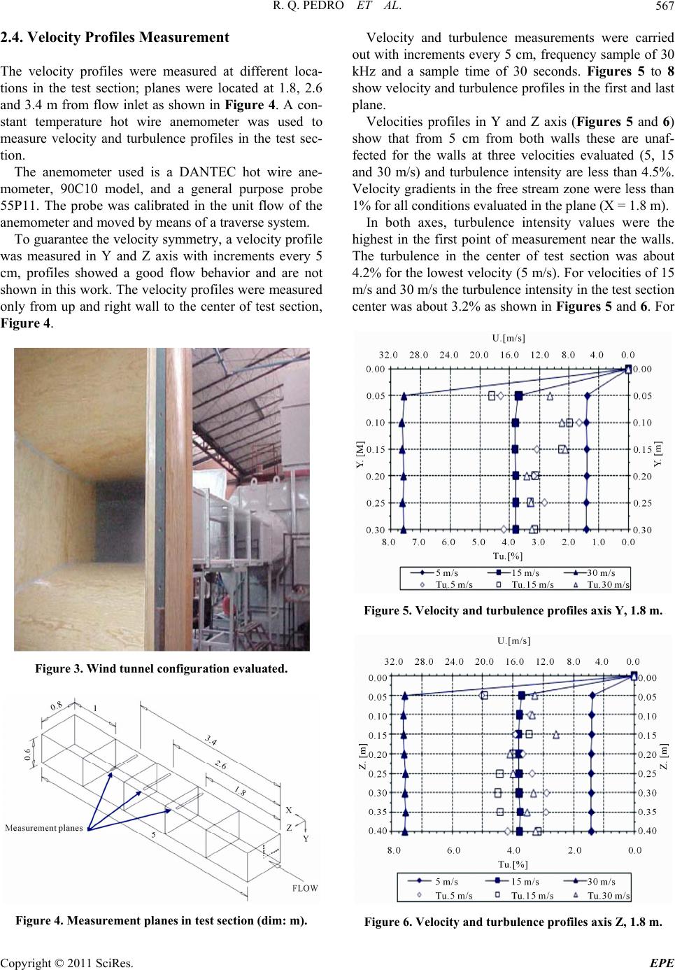
nozzle manufactured with plywood; Figure 3 illustrates
the configuration evaluated in this work.
Figure 2. Modification proposed for wind tunnel.
Copyright © 2011 SciRes. EPE