Open Journal of Civil Engineering
Vol. 3 No. 3 (2013) , Article ID: 36393 , 9 pages DOI:10.4236/ojce.2013.33021
Experimental Investigations of the Shear Capacity of Nails in a Row
1Institute of Technology, Civil Engineering and Architectural Section, The Norwegian University of Life Sciences, Aas, Norway
2Stor-Elvdal Kommune (Stor-Elvdal Municipality), Koppang, Norway
3Venator (Consultants), Oslo, Norway
Email: christian.sørensen@umb.no, rmn@stor-elvdal.kommune, lars@baastad.org
Copyright © 2013 Christian O. Sørensen et al. This is an open access article distributed under the Creative Commons Attribution License, which permits unrestricted use, distribution, and reproduction in any medium, provided the original work is properly cited.
Received May 28, 2013; revised June 28, 2013; accepted July 5, 2013
Keywords: Nails; Shear; Connections; Row; Spacing; Capacities
ABSTRACT
Tests of the capacity of shear connections consisting of nails in a row placed at distances 7, 10 and 14d, “d” being the cross-sectional dimension of the nail, versus single nail capacities, were executed. The performed tests do support the connotation that no reduction should be required for nails of diameter 2.8 mm or less in a row, provided that nails are spaced sufficiently far apart for wood cracking not to occur. At the ultimate capacity of the joint, all such thin nails in a row will be yielding, having developed plastic hinges, i.e. each single nail will have developed its ultimate capacity. Hence, the ultimate capacity of the connection will be each nail’s capacity times the number of nails in the row. The force pr. nail increases subsequent to the development of a plastic hinge. This is likely due to the axial pullout-force, i.e. the ultimate capacity of a shear connection is higher than the force required for developing plastic hinges in the nails. This additional capacity-reserve may also partly be attributed to the rotational resistance of nails. The number of nails in a row should make insignificant difference in the pr. nail capacity, as long as no wood cracking takes place. Thus, applying elastic theory to nails in a row does not seem relevant. This is in contrast to bolt-connections.
1. Introduction
Some variables that affect the capacity of one individual nail, in a shear-type, gusset-plate connection, Figure 1, are member thicknesses, timber density and moisture content, nail cross-sectional shape and area, steel quality and surface texture of the nail, embedment length and angle between direction of force and wood-grain. Common size nails, typically 2.8 mm or less, are prone to cause splitting of the timber due to the “wedging” tendency.
A bolt, on the other hand, will not normally have a tendency to split the wood, as it will be more in a bearing mode against the edge of the predrilled hole. When multiple nails are placed on line in a row, the wedging tendency may be enforced, and increasingly so with de-
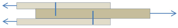
Figure 1. Shear-type nail-connection.
creasing nail spacing, due to “collaboration”, or joint action, between the nails.
Disagreements exist between the various building codes concerning the need to reduce nail capacity when nails are installed in a row in a shear joint. Possibly, some requirements for reduction in capacity of each fastener in multiple-nail joints are based on elastic solutions, which apply to fasteners of greater cross-sectional area, than that of common nails. If splitting of the timber occurs along the fastener rows at load levels below the potential plastic capacity, a full redistribution of the load within the joint is prevented. The chance of splitting may be reduced by increasing the nail spacing and end distances, and by placing nails in a zigzag configuration and by predrilling holes. Such provisions contribute towards a plastic connection behavior. This increases the capacity of multiple-fastener joints beyond predictions based on elastic behavior.
EuroCode 5 [1] recommends that the effective number of nails in a row should be taken as
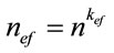 where nef = effective number of nails;
n = number of nails in the row;
kef is listed in Table 1.
The Norwegian structural timber design code recommended that for nails in a row consisting of more than 10 nails, the effective number of nails, nef, should be reduced by allowing only 2/3 of the nails exceeding 10 to be included [2]:
 .
.
2. Purpose and Usefulness
Major areas of application of nails in a row are shear walls and horizontal diaphragms, i.e. in floors and roofs, that are transferring lateral forces caused by seismic action and wind. Commonly, plywood is being nailed to framing members consisting of 2 × 4’s. This research effort is aimed at finding out about the following:
• The legitimacy of applying a reduction factor when nails are placed in a row as specified in NS 3470-1 [2] and in Eurocode 5 [1].
• The influence of c/c distance between nails on the shear capacity of the joint.
• The reasons for a reduction in the shear capacity pr. nail in a row of nails if required.
If proven to be true that the ultimate capacity pr. nail in a row of nails is the same as for one nail in a singlenail connection, an amendment of codes calling for a reduction in the pr. nail capacity of a row of nails may possibly be considered. This could entail reductions in costs due to the smaller number of nails required in certain types of joints.
3. Literature Research
3.1. Bolts in Shear Connections
3.1.1. Bolts in Steel Gusset Plate Connections
A number of bolts, typically the ones near the end of a row, may be loaded to, or beyond, their elastic limit, while other bolts, towards the middle of the row, may not be loaded even close to their elastic limit, Figure 2. Accordingly, the load on the multiple fastener joint, when

Table 1. kef-values.
end-bolts have reached their elastic limit is smaller than the sum of the loads of the single fasteners at their elastic limit [3,4]. Figure 3 displays a plastic failure advancement [3].
According to Cramer [5], unequal bolt load distribution was discovered by J. T. Milton, who applied himself to research on steel structures, in 1885.
3.1.2. Bolts in Timber Shear Connections
Cramer and Lantos [6] made the same observations in the 1960’s on bolted timber structures, as Milton had made on similar all steel connections, ref. the foregoing Section 3.1.1.
It is widely accepted today that the ultimate strength of a multiple-bolt timber joint, loaded statically in one direction, is less than n times the ultimate capacity of a single-bolt joint, where n represents the number of bolts. That is, the individual bolts in a multiple-bolt row do not share the applied load equally, resulting in higher stressed fasteners at certain locations. The outermost bolts at each end transmit a greater proportion of the load

Figure 2. Longitudinal cut thru bolted joint [3].

Figure 3. Bolt forces with connection load Increasing gradually [3].
than the innermost bolts. Lantos (1969) [6] substantiated that bolts in a row in a timber joint do not share the applied load equally.
Hence, for rigid fasteners, such as bolts, the total strength of a multiple-bolt joint, loaded one-directionally, must be smaller than the sum of the capacities of the individual fasteners. To ensure safe design, the concept of effective number of fasteners was introduced [6-8]:

where Z = lateral design load;
neffective = number of fasteners < actual number of fasteners;
K = safety factor.
Lantos’ theory was introduced to the National Design Specification [9] in 1973, with a modification factor table. These factors are being used for reducing the individual bolt capacity in a row of bolts in a shear type connection.
According to Lantos, no bolt would develop a yield hinge, i.e. the failure would take place by either rigid rotation of the connector or because the wood fails by cracking or that the bearing capacity of the wood is exceeded due to pressure other than, or in addition to, that caused by bolt rotation.
3.2. Nails in Shear Connections
Thomas and Malhotra [10] demonstrated that nail joints do exhibit some amount of group action, and, hence, a single-nail joint will behave differently from a joint consisting of several nails in a row. A modification factor was developed to account for this discrepancy.
Carling [11] states that when several nails are placed in a row in the direction of the force, for instance when used with gusset-plates in connections, the capacity is being reduced, and only 2/3 capacity should be allowed on the number of nails exceeding 10. On the other hand, Blass [12] states that “Nailed and stapled joints: Any influence of the number of fasteners on the load-carrying capacity of nailed or stapled connections may be ignored.” And further: “When a connection contains two or more fasteners of the same type and similar size, each of which exhibits the same yield mode, the total allowable design value for the connection shall be the sum of the allowable design values for each individual fastener. Edge distances, end distances and spacings for nails and spikes shall be sufficient to prevent splitting of the wood.”
According to Vaughn [13], to his knowledge, no USA design codes or guidelines addresses this subject for nails, and, accordingly, do not require any capacity-reduction of nails in a row, as long as the spacing between nails is sufficient to avoid crack development.
Isyumov described the plastic hinge failure mode [12] by viewing the behavior of the connectors as nonlinear, which allowed for a redistribution of the load among the connectors. When plastic deformation was initiated at the most highly stressed fastener at the end of the row, it would have reached its ultimate capacity, and an increase in load would have to be distributed to the other connectors. The load would be transferred towards the center of the row. This is in disagreement with Lantos’ theory, as the capacity of each connector will be higher than if the behavior had been elastic.
A wood knot may increase the capacity of a nail because of its higher density.
Whether the connectors display elastic or plastic behavior has an influence on the capacity of the joint. The failure pattern of each nail is mainly determined by factors listed in the introduction to this article, Section 1. If the c/c-distances between nails are too small, splitting of the timber may take place, and the development of plastic hinges in one or more nails may not be possible, which reduces the capacity of the connection.
4. Bolts, as Opposed to Nails, Placed in a Row in a Timber Shear Connection
Based on the preceding assumption concerning differences in behavior between bolts in a row and nails in a row in timber connections, i.e. that all nails in a row will develop plastic hinges, while all bolts will not, it seems reasonable that, as in the past, and also according to some current building codes, that the allowable load on a group of nails should be the product of the allowable value of a single nail and the number of nails in the joint.
5. Single Nail Capacities of Nails Used in This Report, Computed According to Building Codes
Various types of nails were used by each one of the researchers (Nymark, Baastad and Sørensen). The shear capacities of each type of nail, computed according to the Norwegian Code (NS3470), EuroCode 5 and USA-code are listed in Table 2. In all test runs the load was applied in the longitudinal direction of the timber member, i.e. in the general direction of grain, and approximately parallel to grain. An ordinary hammer was used for driving of nails manually, without pre-drilling.
6. Experiments and Results
The investigations required several joints to be fabricated, both multiple nail connections and single nail connections, Figure 4, which were then slowly pulled apart while continuously recording the applied load and the simultaneous displacement.
Knots and cracks in the 2 × 4’s were avoided. Each pair of samples, i.e. the single nail and the multiple nails

Table 2. Characteristic shear design values pr. nail in Newtons.
 (a)
(a) (b)
(b) (c)
(c) (d)
(d) (e)
(e)
Figure 4. Testing configurations. (a) 12 nails in a row shear test piece. Non-yielding part at right; (b) Shear, single nail; (c) Shear, multiple nails; (d) Single nail pullout; (e) Pullout of one single nail from a row of nails.
in a row test specimens, were normally fabricated the same day at Relative Humidity 65% ± 3% at temperature 21˚C ± 3˚C. The moisture content of the 2 × 4’s was ≈ 12%. The corresponding pieces of 2 × 4’s were taken from the same timber stud, adjacent to each other, thus significant density differences were avoided. Edge distances were in compliance with EuroCode 5 [1].
6.1. Nymark’s Tests and Results
Tests:
24 connections with 21 to 26 nails in a row @ 10d.
9 connections with 17 to 19 nails in a row @ 14d.
2 connections with 30 nails in a row @ 7d.
30 single nail connections.
15 mm plywood gussets.
Displacement rate: 2 mm/minute.
Nails: 2.1 × 35 mm, circular, annular, bright.
6.1.1. Nails-in-a-Row, Spacing 7d, and Single Nail Results
When the nail distance was 7d, the average capacity of each nail in the rows was 892 N versus a capacity of 1402 N in a single-nail connection. The statistical significance was high, Table 3.
6.1.2. Nails-in-a-Row, Spacing 10d, and Single Nail Results
When the nail distance in the rows was 10d, the average capacity of each nail in the rows was 1018 N versus a capacity of 1298 N in a single-nail connection. The statistical significance was high, Table 4.
6.1.3. Nails-in-a-Row, Spacing 14d, and Single Nail Results
No statistical significance was found between the singlenail connection capacity, 1331 N, and the average capacity of each nail in the rows, 1114 N, when the spacing was 14d, Table 5.
6.1.4. Evaluation of Tests
A few test specimens were partitioned subsequent to test
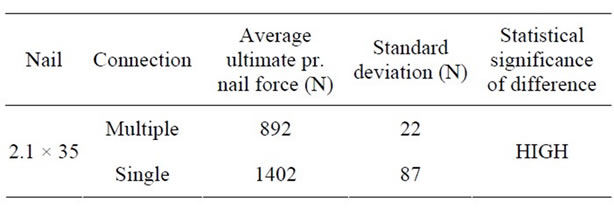
Table 3. Nails in a row @ 7d versus single nail ultimate pr. nail force.

Table 4. Nails in a row @ 10d versus single nail ultimate pr. nail force.
runs with the intent to clarify the behavior of nails and timber pieces during the test.
1) 7d nail spacing The test piece partly displayed in Figure 5, had been loaded to maximum capacity, followed by a reduction in load to 80% of maximum load. The plywood side plates were removed by cutting the nails. The cracks are clearly visible, and it is also apparent that nails were not placed exactly on a line.
During tests in progress, a crackling sound was heard, a clear indication of splitting taking place. Sometimes the sound was local, and sometimes it sounded like an “avalanche” was going thru the test piece, according to Nymark, an indication that splitting between nails 1 and 2 affects and expedites splitting between nails 2 and 3 and so forth. As expected, the tests manifests a clear tendency of several nails in a row to possess, Table 3, less capacity than one nail by itself. This means that the wood is being weakened due to e.g. increased “wedging” caused by “cooperation” of the nails in the row.
2) 10d nail spacing This is the minimum allowable nail spacing according to the Norwegian Code, NS3470-1 [2]. Nymark’s test results indicate a substantial reduction of the capacity pr. nail in a multiple-nails-in-a-row connection compared to the capacity of a single nail joint, Table 4. Nymark found, by removing timber material to the extent that nails became exposed, that all nails had developed plastic hinges, Figure 6, which also shows that the nail has been slightly pulled out axially.

Table 5. Nails in a row @ 14d versus single nail ultimate pr. nail force.

Figure 5. 7d nail spacing cracks.
One 10d test-run was terminated at the ultimate load, and the plates removed by cutting them to pieces. No cracking is visible, only damage at the location of each nail-hole, Figure 7.
3) 14d nail spacing EuroCode 5 permits full pr. nail capacity when nails, placed in a row parallel to the applied force direction, are spaced at 14d.
Nymark’s findings are possibly slightly in conflict with this, even though there was no statistical significance between the 19% higher single nail capacity and the pr. nail capacity in the row, Table 5.
6.1.5. Observations from, Discussion of, and Conclusions from Nymark’s Results
Single nail test results, Table 6, indicated that the force required for pullout was higher than the force required for developing a plastic hinge in a nail.
6.2. Baastad’s Tests and Results
Tests:
Smooth (Figure 8):
22 nails in a row @ 7d: 5 tests 12 nails in a row @ 14d: 10 tests Single-nail: 12 tests

Figure 6. Plastic hinges and initiated pullout.
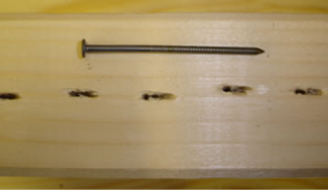
Figure 7. 10d spacing. No visible cracks.

Table 6. Percentage higher ultimate force on nail in singlenail connections versus pr. nail-ultimate-force on a multiple nails-in-a-row connection.

Figure 8. Left: annular nail; middle: smooth nail; right: screw utilized at non-yielding part of test-piece.
2.8 × 55 smooth, galvanized finish, head dimension: 8.7 mm.
Annular (Figure 8):
22 nails in a row @ 7d: 5 tests.
12 nails in a row @ 14d: 5 tests.
Single-nail: 12 tests.
2.8 × 55 annular, galvanized finish, head dimension: 7.5 mm.
Displacement rate: 4 mm/minute, all runs.
Plywood gusset plate thickness: 15 mm all test pieces.
6.2.1. Nails-in-a-Row, Spacing 7d, and Single Nail Results
High statistical significance was found between single nail capacities in single-nail connections and the capacity of each nail in the rows when nails were spaced at 7d, Table 7.
6.2.2. Nails-in-a-Row, Spacing 14d, and Single Nail Results
At 14d nail spacing, there was no statistically significant difference between the single nail capacity and the pr. nail capacity in the row, Table 8.
6.2.3. Observations from, Discussion of, and Conclusions from Baastad’s Results
Only local cracks, barely visible, in the vicinity of each nail at 7d spacing took place in lower density timber, Figure 9, while continuous cracking was observed at 7d spacing at high timber density, Figure 10, indicating the influence of timber density on crack development.
The results uniformly manifests that the shear capacity pr. each single nail in a row at 7d is less than when placed at 14d. However, single nails do not display a greater capacity than nails in a row at 14d.
The results also reveal that 14d may possibly be the distance required for the full capacity to be employed.
6.3. Sørensen’s Tests and Results
Series I tests:
10 nails in a row @ 10d: 11 tests.

Figure 9. Local cracking.

Figure 10. “Global” cracking.

Table 7. Nails-in-a-row @ 7d, and single nail results.

Table 8. Nails in a row @ 14d versus single nail ultimate pr. nail force.
12 nails in a row @ 10d: 5 tests.
11 nails in a row @ 10d: 4 tests.
Single-nail: 12 tests:
Nails: 2.8 × 55 mm, head: 8 mm.
Plywood thickness: 10 mm.
Displacement rate: 10 mm/minute except for 5 test runs at 2 mm/minute.
Series II tests:
16 nails in a row @ 10d: 6 tests.
19 nails in a row @ 10d: 2 tests.
15 nails in a row @ 10d: 4 tests.
17 nails in a row: @ 10d: 2 tests.
Single-nail: 15 tests:
Nails: 1.7 × 35 mm, head: 4 mm.
Plywood thickness: 12 mm.
Displacement rate: 10 mm/minute.
6.3.1. 2.8 × 55 mm Nails @ 10d
No statistically significant difference was found between single nail connection capacity and the capacity of each nail in the rows, Table 9.
6.3.2. 1.7 × 35 mm Nails @ 10d
No statistically significant difference was found between single nail connection capacity and the capacity of each nail in the rows, Table 10.
6.3.3. Observations, Discussion of, and Conclusions from Sørensen’s Results
The tests do support the connotation that no reduction should be required for nails of diameter 2.8 mm and less in a row of nails spaced at 10d as there is no statistical significance between the capacity pr. nail in the rows and single nail connection capacity.
7. Discussion and Follow-Up Recommendations
The obtained test-results do support the USA-connotation that no reduction should be required for nails of diameter 2.8 mm and less in a row. Near the ultimate capacity of the joint, all such thin nails in a row, even if exceeding 10, will be yielding, having developed plastic hinges, i.e. each single nail will have developed its ultimate capacity. Hence, the capacity of the connection will be each nail’s capacity times the number of nails in the row. However, more tests should be done, including tests on longer rows of nails, i.e. a greater number of nails in a row, for instance 20 - 40 nails, and nails of other diameters than 1.7 and 2.8 mm. Also, tests on nails driven in other directions and angles relative to the grain direction may be of interest, as well as utilizing other types of gussets than plywood.
Use of tomography may be useful in verifying the shape of deformed nails subsequent to connection failure. Tomography, however, may or may not give useful pictures of nail deformation, according to Dalen [14].
8. Justification of the Experimental Results
8.1. Multiple Nails Act Together to Increase the Wedge Effect
The wedging effect of each nail in a row of several nails will add up, and as the nail spacing decreases, the amount of wood to resist the tendency of the force transverse to fiber direction, due to wedging, to pull fibers apart, will be reduced.
8.2. Transverse Nail Forces Due to Moment in Connections with 2 or More Nails in a Row in the Direction of the Force
The reason for the pullout force (rope-effect) on a nail possibly being lower when a nail is placed in a row may partly be due to the adjacent nails exerting forces transverse to the direction of the applied force. These forces, generated by local moment, could cause wood fibers to be less tightly connected. This would reduce the holding power of the wood fibers on e.g. the middle nail in Figure 11. The moment may be due to local eccentricities, e.g. nails not being placed exactly on line, and/or not being on the line of action of the applied linear force.

Table 9. Nails in a row @ 10d, and single nail results.

Table 10. Nails in a row @ 10d, and single nail results.

Figure 11. Multiple nails, eccentric loading causes no rotation of connection, but implies transverse forces.
The closer the nails, the less timber there is between nails to resist the transverse force which causes stress in the weakest timber direction, and also the transverse force will increase with decreasing nail spacing.
8.3. Each Nail Will Develop Plastic Hinges
Every single nail in a row with adequate nail spacing, will develop plastic hinges, which corresponds to what could be called the initial ultimate capacity. Subsequent additional ultimate capacity may be generated from pullout resistance, i.e. the rope effect. This is in contrast to bolts, since all bolts in a multiple fastener timber joint, will not, as the case is in steel gusset plate shear connections, develop plastic hinges prior to timber failure.
9. Summary and Conclusive Remarks of This Report
The actual ultimate shear force pr. nail in all test-runs of nails spaced at 14d exceeds the capacity computed according to codes. This implies that the code-capacities could be used, without reduction, as long as the nail spacing is large enough to avoid splitting. Applying the elastic theory to nails in a row does not seem relevant, as all nails in a row develop plastic hinges, provided that no splitting occurs.
The number of nails in a row should make insignificant difference, if any, in the pr. nail capacity, as long as no cracking takes place. A reduction to 2/3 capacity, for instance, applied to the number of nails beyond 10 in a row, seems unjustified, but may be applicable to bolts, as all bolts in a row normally will not be yielding in a timber joint.
The force pr. nail increases subsequent to the development of a plastic hinge. This is likely attributable to the rope-effect, i.e. the axial pullout-force in the nail, or withdrawal of the nail, in a shear-connection. In other words, the ultimate capacity on a shear connection is higher than the force required to develop plastic hinges in the nails in a row. This additional capacity-reserve may also partly be attributed to the nail’s rotational resistance.
10. Final Conclusions of This Report
The test results do indicate that no capacity-reduction should be a requisite for placing nails in a row, which is in agreement with US-codes not calling on any capacity-reduction at all /7/ /2/ /12/, provided that nails are spaced sufficiently far apart to avoid splitting of the wood.
The spacing requirement >14d of EuroCode 5 for allowing ultimate nail capacity, may not be adequate for the ultimate capacity to develop, although sufficient for allowing characteristic code-values without reduction. If a minimum spacing requirement is to be specified, in lieu of “spaced sufficiently apart to avoid cracking”, this should be related to timber density and moisture content.
11. Acknowledgements
The support from The University of Life Sciences is recognized. The advice from Egil A. Berge, Professor Emeritus, on statistical significance computations, is appreciated as is the assistance by Professors Geir Vestøl and Olav Høibø in coordinating equipment-use and demonstrating testing machinery. Assistant Professor NilsIvar Bovim’s general advice during the project is appreciated. The assistance by Bjørn Slette, Carpentry Workshop Manager, and Bjørn Brenna, Mechanical Workshop Manager, in providing supply and in fabricating equipment as needed, is appreciated as is the assistance from Senior Engineers Tom Ringstad and Andreas Flø with the data-equipment and measuring devices.
REFERENCES
- EuroCode 5, EN 1995-1-1:2004, “Design of Timber Structures,” Part 1-1: General—Common Rules and Rules for Buildings, 2004.
- NS 3470-1, “Prosjektering av Trekonstruksjoner,” 1999. www.standard.no
- Beedle, et al., “Structural Steel Design,” Lehigh University, Bethleham, 1964, pp. 568-570.
- H. J. Blass, et al., “Basis of Design, Material Properties, Structural Components and Joints,” Centrum Hout, The Netherlands, 1995.
- C. O. Cramer, “Load Distribution in Multiple-Bolt Tension Joints,” Journal of Structural Division, Vol. 94, No. 5, 1968, pp. 1101-1117.
- G. Lantos, “Load Distribution of a Row of Fasteners Subjected to Lateral Load,” Wood Science, Vol. 1, No. 3, 1969, pp. 129-136.
- H. A. Fahlbusch, “Contribution to the Problem of Bearing Strength of Bolts in Wood under Static Load,” Report No. 49-09, Institute for Mechanical Construction and Carpentry, Braunschweig, 1949.
- A. Jorissen, “Bolted Connection Testing,” Royal Military College of Canada, Kingston, 1996.
- “National Design Specification for Wood Construction,” American Forest and Paper Association, American National Standard, Washington DC, 1997.
- Thomas & Malhotra, “Bolted Connections,” 1985. http://scholar.lib.vt.edu/theses/available/etd-08132002-140200/unrestricted/Chapter2.pdf
- O. Carling, et al., “Dimensionering av Träkonstruktioner,” AB Svensk Byggtjänst, Solna, 1992.
- H. J. Blass, et al., “Basis of Design, Material Properties, Structural Components and Joints,” Centrum Hout, The Netherlands, 1995.
- W. B. Vaughn, “Consulting Structural Engineer,” Vaughn Engineering, 2010.
- K. S. Dalen, “Senior Engineer,” Institutt for Husdyr-og Akvakulturvitenskap, Norway, 2009.