Journal of Electromagnetic Analysis and Applications
Vol.4 No.2(2012), Article ID:17673,5 pages DOI:10.4236/jemaa.2012.42012
Risk of Pacemaker Patients by TASER X26 Contact Mode Application*
![]()
Institute of Health Care Engineering with European Notified Body of Medical Devices, Graz University of Technology, Graz, Austria.
Email: norbert.leitgeb@tugraz.at
Received December 22nd, 2011; revised January 20th, 2012; accepted January 29th, 2012
Keywords: Conducted Energy; Numerical Simulation; Anatomical Model; Health Risk; Electromagnetic Compatibility
ABSTRACT
The prevalence of pacemaker patients among the general population and of conducted energy devices (CED) for law enforcement and self-defence is increasing. Consequently, the question whether cardiac pacemaker (CPM) patients are on particular risk becomes increasingly important. The risk of Taser X26 electric interference with implanted CPM has been investigated by numerical simulation at MRI-based anatomical models of CPM patients with devices implanted at conventional sites (left pectoral, right pectoral and abdominal) and with the monopolar CPM electrode placed at the ventricular apex. In spite of 10 fold higher peak voltages the different coupling conditions make Taser-induced CPM interference voltages lower than those caused by external cardiac defibrillators. It is shown that electric interference considerably depends on ECD electrode orientation. The most unfavourable conditions are encountered with ECD electrodes aligned with the line from the CPM electrode tip to CPM can (EPC line). It could be shown that worst case interference voltages of monopolar pacemakers of any kind of implantation remain below the pulse immunity level as defined in safety standards of implantable cardiac pacemakers and of cardioverter defibrillators. However, interference voltages exceed CPM sensing thresholds. Therefore, capturing should be expected at Taser X26 contact mode application at any position at the upper part of the body including the abdomen, both at frontal and dorsal positions.
1. Introduction
The prevalence of pacemaker patients among the general population and of application of conducted energy devices (CED) for law enforcement and self-defence is increasing. Consequently, the question whether cardiac pacemaker (CPM) patients are at particular risk becomes increasingly important. Electric high-tension pulses of CEDs such as Taser® weapons are used for law enforcement to incapacitate subjects by delivering short-term high-tension pulses. This is done either in distance mode by firing dart electrodes towards the subject or in contact mode by directly pressing the weapon and its integrated two contact electrodes against the body. The Taser X26 emits 5 s long series of pulses with about 18 Hz repetition frequency. Applied voltages depend on load resistance and, hence, on the application site at the body. Since voltages may considerably exceed those of external defibrillators which are limited to 5 kV [1] and are known to be potentially harmful to implanted electronic devices concerns are raised CEDs could also critically damage implanted pacemakers and cardioverter defibrillators.
In Germany the annual pacemaker implantation rate is about 0.09% of the population. With an average CPM lifetime of 9.8 years the prevalence of pacemaker patients can be estimated to about 0.8% of the population [2] Since CEDs are increasingly used—in the USA already more than 15.000 law enforcement and military agencies use them to incapacitate subjects [3]—the probability of applying CEDs to pacemaker patients is increasing. Therefore, there is a need to investigate the potential risk for persons with electronic implants and to quantitatively assess the potential consequences of this kind of electric interference.
Implanted cardiac stimulators (pacemaker or cardioverter defibrillators) are able to adjust their stimulation rate to physiologic needs by measuring patient’s (residual) intrinsic cardiac activity (electrocardiogram, ECG) via a sensing electrode fixed within the cardiac muscle of either the atrium or ventricle. However, this beneficial approach constitutes also an Archilles heel because input signals make the system vulnerable to induced interference voltages which may be confused with cardiac activity and degrade CPM function. Taser pulses generate 3D intracorporal electric field distributions and, consequently, differences of electric potentials which may be picked up between the tip of the cardiac CPM electrode and the pacemaker can and become interference voltages which add to or replace cardiac ECGs. Usually, pacemaker cans are implanted at the upper part of the body below the clavicle at the left side (left-pectoral) with the electrode forwarded along blood vessels to the target cardiac region such as the ventricular apex (Figure 1). An alternative is right-pectoral implantation with electrode insertion into vena cepahlica or subclavia; respectively. In rare cases the pacemaker is placed in abdominal position. Preferably pacing is done via a bipolar electrode which is less sensible to interference. However, with implantation time due to tissue reactions stimulation efficiency reduces. This may make it necessary to switch to the monopolar mode which is more vulnerable to interference.
Experimental results in swine models reported no significant functional changes due to Taser application [4]. In contrast, from human case reports it was concluded that Taser pulses may cause interference with implanted cardiac pacemakers and functional changes such as tachycardial stimulation, reversion to fix-frequency interference mode and inappropriate sensing [5-7]. However, in view of the diversity of existing pacemaker models and specific device settings experimental studies do hardly allow general conclusions, and quantitative dosimetric studies are lacking.
To fill this gap by numerical anatomical modelling this paper quantitatively estimates interference voltages of monopolar pacemakers induced by Taser X26 pulses delivered in contact application.
To allow assessment independent from specific pacemaker models results are compared with requirements of medical device safety standards.
2. Method
Intracorporal electric field distributions have been determined by numerical simulation. This was performed at self-generated models of pacemaker patients based on the anatomical model NORMAN, an MRI-based model of an average European man (73 kg, 176 cm) with a spatial resolution of 2 × 2 × 2 mm voxels, segmented into 35 different biologic tissues [8]. Dielectric values of body tissues were taken from [9]. Three different models of pacemaker patients have been created by implanting a digital model of a cardiac pacemaker (Medtronic 8423 M). The pacemaker can with perfect electric conductivity was implanted at the conventional sites left-pectoral, right-pectoral and abdominal below the cutis; the isolated monopolar electrode was inserted into the vein, pushed forward and finally contacted to the right ventricular apex (Figure 1).
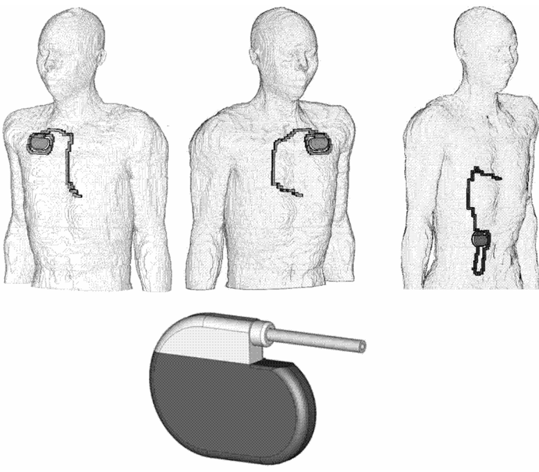
Figure 1. Numerical anatomical models with pacemakers implanted in right-pectoral (left), left-pectoral (middle) and abdominal position (right), numerical CPM model (below).
Calculation of the induced intracorporal electric field distribution was performed by solving Maxwell’s equations based on the Finite Integration Technique with the software package CST Studio® Suite 2009 [10].
Taser X26 application was studied with CED electrodes kept in the constant distance of 38 mm according to contact mode application. They were placed at various positions at the upper part of the body both frontal and dorsal. At each position investigation was performed in two orthogonal orientations of the CED electrodes. From fundamental physics the worst case could be expected at alignment along the line from the pacemaker electrode tip to the pacemaker can (EPC line); some slight deviations from the EPC line were necessary due to anatomical reasons (e.g. ribs). For practical reasons distant from the EPC line investigated orientations were vertical and horizontal, respectively.
From the 3D intracorporal electric field distribution pacemaker interference voltages were assessed by determining the electric potential difference between pacemaker electrode tip and pacemaker can. The load-dependence of delivered Taser pulses was accounted for by numerical calculation of position-dependent body impedances and selecting delivered Taser X26 pulses from the results of own measurements accordingly. For this purpose the delivered Taser X26 pulses had been measured [11,12]. Calculated body impedances have been verified by directly measuring body impedances at volunteers with constant contact pressure.
3. Results
Taser X-26 weapons deliver 5 s long series of pulses repeated with about 18.4 Hz. After an oscillating onset phase the main pulse lasts for about 100 µs. Pulse parameters including time course and repetition frequency vary with load impedance [11-13]. Depending on electrode location the pulse peak amplitude extended to 12 kV (the open circuit voltage exceeded 70 kV). A part of delivered voltages is picked up by the pacemaker.
Delivered CED pulses generate intracorporal electric field distributions with an equipotential zone midway between and fairly perpendicular to the line connecting the two Taser contact electrodes (TCE line) with some variation due to anatomical inhomogeneities. For worst case coupling the electric field distribution is shown within intracorporal planes across the pacemaker can and the ventricular electrode tip for the three different pacemaker patient models (Figure 2). It can be seen that the highest gradient of the intracorporal electric field is found along the TCE line. This explains why the highest interference voltage is encountered in case of electrode alignment along the EPC line. This was confirmed at all three types of implantation.
The highest interference voltages were induced with CED electrodes positioned at one of either end of the EPC line. With increasing distance to the EPC line interference voltages decrease rapidly. With the pacemaker can in left pectoral position the maximum interference voltage with electrodes along the EPC line amounted to 11,500 mVpeak. In the less efficient orientation perpendicular to the EPC line the interference voltage was reduced to 480 mVpeak (Figure 3). However, results demonstrate that orientation counts even if the CED is applied distant from the EPC line with up to 10 fold higher interference voltages for vertical orientation (Figure 3) compared to the horizontal case (Figure 4).
With the electrode at the back at the position corresponding to the frontal worst case position the interfereence voltage was reduced to 580 mVpeak. This is about 20 fold lower than the frontal result but still 290 fold above
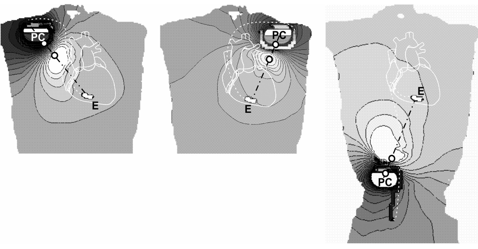
Figure 2. Worst case electric field distributions within intracorporal planes across pacemaker can (PC) and electrode tip (E); pacemakers implanted in right-pectoral (left), left-pectoral (middle) and abdominal position (right). Black lines… equipotential lines, white circles… electrode positions at body’s surface.
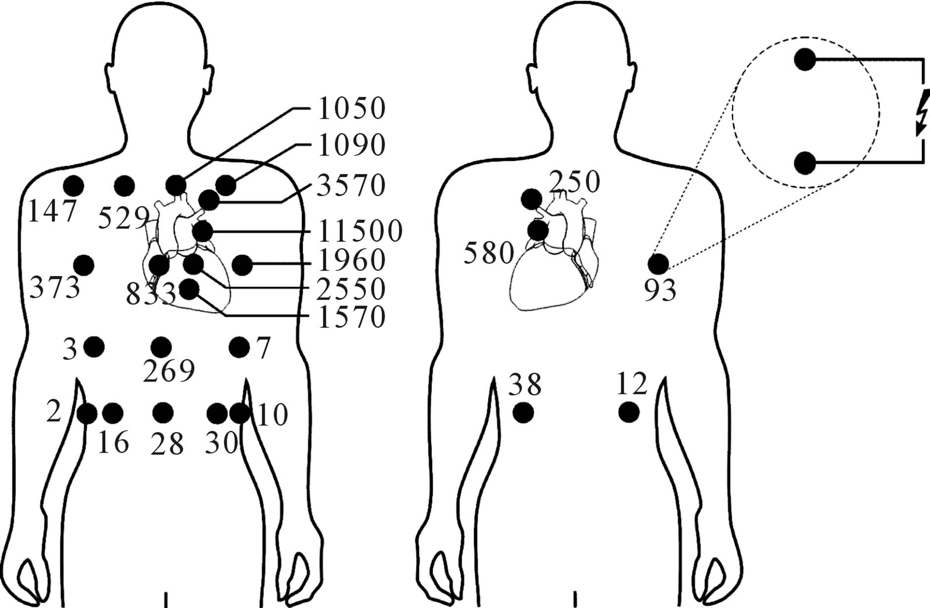
Figure 3. Pacemaker interference voltages (numbers in mV) induced by Taser X26 pulses in a patient with pacemaker implanted at left-pectoral site with CED electrodes in vertical (or EPC line-aligned) orientation at frontal (left) and dorsal positions (right).

Figure 4. Pacemaker interference voltages (numbers in mV) induced by Taser X26 pulses in a patient with pacemaker implanted at left-pectoral site with CED electrodes in horizontal orientation (or perpendicular to the EPC line).
the conventional pacemaker sensing threshold of 2 mVpeak-peak. Even if Taser X26 pulses are delivered in the abdominal region and in the back the interference voltage remains still about one order of magnitude above the pacemaker sensing limit. Applications at the back cause smaller interference voltages compared to frontal, however, not at any position. In general interference voltages were well above 2 mVpeak (Figures 3 and 4). At other types of implantation the worst case interference voltage was in the same range than the left pectoral case. The worst case of right-pectoral implantation was 9100 mVpeak. With the pacemaker in abdominal position, the worst case amounted to 9000 mVpeak.
4. Discussion
Taser devices deliver peak voltages which may be one order of magnitude higher than pulses of external defibrillators. For pacemakers implanted at left-pectoral site simulation results showed that in worst case (defibrillator electrodes placed medial and lateral of the heart) and maximum output voltage (5 kVpeak) the induced interference voltage amounted to critical 676,000 mVpeak. This explains existing concerns that the higher Taser X26 pulses might damage pacemakers. However, results showed that interference voltages induced by worst case contact application are 59 fold lower than those of external defibrillators. This can be explained by the smaller contact area and smaller spacing of Taser X26 contact electrodes and, therefore, less efficient intracorporal electric field distributions.
The use of the numerical anatomical model of a slim man is already widely accepted and validated for investigations of different kind of electric and electromagnetic interference [8,12,14]. It could be expected that CED application at larger and/or more obese persons would lead to lower interference voltages. This was confirmed by additional simulations made with the Visible Human model of an adult man (103 kg, 186 cm) with the body mass index 29.8 (which is higher than NORMAN’s 23.6). In that case the worst case interference voltage was found to be reduced by 19.6%.
To assess the impact of electric interference the results were compared to the requirements on electromagnetic immunity as defined in medical safety standards of electronic implants. This should allow general device-independent conclusions. Safety standards of implantable cardiac pacemakers [15] and of cardioverter defibrillators [16,17] define immunity levels against adverse effects of electromagnetic interference by sinusoidal signals, pulses and transients. Therein, interference is defined as “any harm caused by device’s susceptibility to electric influences, in particular any device malfunction persisting after exposure”. It is required to test potential induction of harmful malfunction with various test signals such as sinusoidal signals (continuous and pulsed) and transients.
Since application of external defibrillators to pacemaker patients cannot be excluded, standards require that cardiac pacemakers and cardioverter defibrillators shall not be damaged and their function not be critically degraded by interference pulses up to 270 Vpeak. From this requirement it can be concluded that even worst case Taser contact application interference voltages of 11.5 Vpeak as encountered in this study should not cause adverse effects in electronic medical implants.
The vulnerability of capturing interference signals depends on the pre-set sensing level of cardiac pacemakers. The most appropriate sensing setting for EMC tests is assumed to be 2 mVpeak-peak for monopolar and 0.3 mVpeak-peak for bipolar electrode configurations [17,18]. However, it is acknowledged that state of the art pacemakers can be adjusted to even more sensitive settings such as 0.1 Vpeak-peak. However, in such cases devices may become already vulnerable also to intracorporal biosignals, and physicians have to decide upon such a tradeoff. Simulation results demonstrate that Taser X26 interference peak voltages are well above these sensing thresholds. At pectoral implantation (left or right) they are about two orders of magnitudes higher in the thorax region and still the 10 fold at abdominal sites. In case of abdominally implanted pacemakers higher voltages can also be induced by abdominal hits. Therefore, with a pulse repetition frequency of about 18 Hz right in the frequency bandwidth of the ECG sensing of Taser X26 pulses should be expected at almost any hit position at the upper part of the body, thorax and abdomen. This is independent from the orientation of the contact electrodes and includes frontal and dorsal hits.
However, in daily life sensing and capturing are no rare events. Existing exposure limits of electromagnetic fields such as of electrical appliances and power supply facilities are not set low enough to exclude such interference [19]. The health relevance of such effects depends on the type of the implanted pacemaker. In general, usually via a separate electrode pacemakers monitor the cardiac activity by sensing (residual) electrocardial biosignals. They might either be used to trigger cardiac pacing (triggered pacemakers) or to inhibit pacing as long as an ECG is generated by the heartbeat; pacing is started again if biosignals disappear and own heartbeats are lacking (demand pacemakers). Today, pacemakers are programmable and operation mode and pacing parameters set (and adapted) by transmitted electromagnetic codes.
If interference signals are stronger than biosignals pacemakers are able to identify such interference, transiently switch to an asynchronous fix-frequency safety mode and pace with constant rate. If interference signals are suitable to mimic cardiac biosignals depending on pacemaker’s operation mode they may either inhibit or trigger pacing. Inhibition can be ignored, if at the same time the heartbeat is generated by the patient, anyway. If not, this can be tolerated if it lasts only for a 5 s Taser X26 pulse series. Triggering may increase pacing rate, however, only up to a device-specific maximum rate (runaway protection) which for several seconds can be tolerated as well. However, it cannot be excluded that interference could cause persisting change of the operation mode of programmable devices with potential adverse consequences although with much lower probability of occurrence.
This investigation is concentrating on hazards of pacemaker patients related to their CPM. Other sideeffects such as adverse tissue heating or cardiac fibrillation were not investigated. The risk of Taser X26-related cardiac fibrillation has already been analysed in [11], the exposure to Taser X26-induced myocardial current densities has been quantitatively analysed in [12].
5. Conclusion
At contact application Taser X26 interference with implanted cardiac pacemakers must be taken into account at the entire upper part of the body, both frontal and dorsal. In general, horizontal orientation of Taser weapons proved to be considerably less efficient in inducing interference voltages than vertical orientation. While interference voltages are not high enough to critically damage pacemaker function, sensing and capturing must be expected at any position at the upper part of the body, frontal and dorsal irrespective the site of implantation.
6. Funding
This work was supported by the Austrian Association for Research Funding in co-operation with the Austrian Ministries of Internal Affairs, Justice and National Defence.
7. Acknowledgements
The authors wish to thank Dr. P. Dimbylow, Health Protection Agency, for providing his numerical model NORMAN.
REFERENCES
- IEC 60601-2-4, “Medical Electrical Equipment Part 2. Particular Requirements for the Safety of Cardiac Defibrillators and Cardiac Defibrillator-Monitors,” 2010.
- A. Markewitz, “Annual Report on the German Cardiac Pacemaker Register,” 2011. http://www.pacemaker-register.de
- E. H. Holder Jr., L. O. Robinson and J. H. Laub, “Police Use of Force, Tasers and Other Less-Lethal Weapons,” National Institute of Justice Report, 2011. http://www.ncjrs.gov/pdffiles1/nij/232215.pdf
- D. Lakkireddy, D. Wallick, K. Ryschon, M. Chung, J. Butany, D. Martin, W. Saliba, W. Kowalewski, A. Natale and P. Tchou, “Effects of Cocaine Intoxication in the Threshold for Stun Gun Induction of Ventricular Fibrillation,” Journal of the American College of Cardiology, Vol. 48, No. 4, 2006, pp. 805-811. doi:10.1016/j.jacc.2006.03.055
- S. R. Vanga, S. Bommana, M. W. Kroll, C. Swerdlow and D. Lakkireddy, “TASER Conducted Electrical Weapons and Implanted Pacemakers and Defibrillators,” Proceedings of the International Conference IEEE EMBS, Minneapolis, 2-6 September 2009, pp. 3199-3204.
- Taser Inc., “Taser® X3TM, X26TM, and M26TM ECD Warnings, Instructions, and Information: Law Enforcement,” Taser International Inc., Scottsdale, 2009.
- M. Cao, J. S. Shinbane, J. M. Gillberg and L. A. Saxon, “Taser-Induced Rapid Ventricular Myocardial Capture Demonstrated by Pacemaker Intracardial Electrograms,” Journal of Cardiovascular Electrophysiology, Vol. 18, No. 8, 2007, pp. 876-879. doi:10.1111/j.1540-8167.2007.00881.x
- P. J. Dimbylow, “FDTD Calculations of the Whole Body Averaged SAR in an Anatomically Realistic Voxel Model of the Human Body from 1 MHz to 1 GHz,” Physics in Medicine and Biology, Vol. 42, 1997, pp. 479-490. doi:10.1088/0031-9155/42/3/003
- S. R. Gabriel, W. Lau and C. Gabriel, “The Dielectric Properties of Biologic Tissues: Measurement in the Frequency Range 10 Hz - 20 GHz,” Physics in Medicine and Biology, Vol. 41, 1996, pp. 2251-2269. doi:10.1088/0031-9155/41/11/002
- CST Studio® Suite 2009, “CST GmbH, Bad Nauheimer Straße 19, D-64289,” Darmstadt, 2009. www.cst.com
- N. Leitgeb, F. Niedermayr, G. Loos and R. Neubauer, “Cardiac Fibrillation Risk of Taser X-26 Dart Mode Application,” Wiener Medizinische Wochenschrift, Vol. 161, No. 21-22, 2011, pp. 571-577. doi:10.1007/s10354-011-0038-z
- N. Leitgeb, F. Niedermayr, R. Neubauer and G. Loos, “Numerically Simulated Cardiac Exposure to Electric Current Densities Induced by TASER X-26 Pulses in Adult Men,” Physics in Medicine and Biology, Vol. 55, 2010, pp. 6187-6195. doi:10.1088/0031-9155/55/20/010
- Taser Inc., “TASER® Electronic Control Devices. Electrical Characteristics—X-26TM,” Taser International Technical Specifications, 1 February 2009.
- N. Leitgeb, A. Omerspahic and F. Niedermayr, “Exposure of Non-Target Tissue in Medical Diathermy,” Bioelectromagnetics, Vol. 31, 2010, pp. 12-19.
- IEC 45502-1, “Active Implantable Medical Devices Part 1: General Requirements for Safety, Marking and Information Provided by the Manufacturer,” 1997.
- EN 45502-2-2, “Active Implantable Medical Devices. Part 2-2: Particular Requirements for Active Implantable Medical Devices Intended to Treat Tachyarrhythmia (Includes Implantable Defibrillators),” 2008.
- ANSI/AAMI PC69, “Active Implantable Medical Devices-Electromagnetic Compatibility-EMC Test Protocols for Implantable Cardiac Pacemakers and Implantable Cardioverter Defibrillators,” 2007.
- IEC 45502-2-1, “Active Implantable Medical Devices. Part 2-1: Particular Requirements for Active Implantable Medical Devices Intended to Treat Bradyarrhythmia (Cardiac Pacemakers),” 2003.
- ICNIRP, “Guidelines for Limiting Exposure to TimeVarying Electric and Magnetic Fields (1 Hz to 100 kHz),” Health Physics, Vol. 99, No. 6, 2010, pp. 818-836.
NOTES
*Conflict of interest: the authors declare no conflict of interest.