Journal of Power and Energy Engineering
Vol.07 No.09(2019), Article ID:95437,14 pages
10.4236/jpee.2019.79006
Research on Parameter Collaborative Configuration of DC Circuit Breaker and DC Fault Current Limiter
Lu Qu, Zhanqing Yu, Zhichang Yuan
Department of Electrical Engineering, Tsinghua University, Beijing, China

Copyright © 2019 by author(s) and Scientific Research Publishing Inc.
This work is licensed under the Creative Commons Attribution International License (CC BY 4.0).
http://creativecommons.org/licenses/by/4.0/


Received: July 24, 2019; Accepted: September 24, 2019; Published: September 27, 2019
ABSTRACT
Fault current suppression is the key technology to ensure the safe operation of the DC power distribution system. In order to realize the parameter collaborative configuration of the DC circuit breaker and the DC current limiter and improve the fault current suppression capability, the fault current suppression mechanism of the DC power distribution system is revealed based on the circuit model. Then, based on the mathematical model of the DC breaker, the characteristic parameters of DC breaking are extracted, and then the influence of different characteristic parameters on the breaking characteristics of fault current is studied. Finally, the mathematical model of the collaborative process between DC circuit breaker and DC current limiter is established. The characteristic parameters of fault current collaborative suppression are extracted. The coupling effects of different characteristic parameters on the fault current collaborative suppression are studied. The principle of collaborative configuration of DC circuit breaker and DC current limiter is proposed, and the collaborative suppression ability of DC circuit breaker and DC current limiter to fault current is fully exploited to ensure the safe and reliable operation of the DC power distribution system.
Keywords:
DC Power Distribution System, Fault Current, DC Circuit Breaker, DC Current Limiter

1. Introduction
With the rapid development of the distributed generation, the increasing DC load and the widespread application of energy storage, the problems of high loss of the AC/DC energy conversion, poor flexibility of the distribution transformation and low matching of the distribution links in traditional AC distribution systems are becoming increasingly prominent. In addition, with the increasing demand of customers for power quality and reliability, the traditional AC distribution system is facing new challenges in power supply stability, economy and other aspects, which can’t meet the demand of DC power access and flexible power consumption. Because of its advantages of high efficiency, large power supply capacity, low line loss, good power quality, no reactive power compensation, and suitable for distributed power supply, energy storage devices and DC load access, the DC distribution system is helpful to solve a series of new problems in the development of the traditional AC distribution system, and is an important development direction of the distribution system [1] - [5] .
Compared with the traditional HVDC transmission and flexible DC transmission, although the voltage level of the DC power distribution is relatively low, the main wiring structure and the operation mode are more complicated and diverse, which leads to more fault modes, faster development of faults, a wide range of impacts and large energy release of the DC distribution system. In addition, the natural property of the DC current without zero-crossing leads to the high requirement of breaking capacity and breaking time for equipment relying solely on the DC circuit breaker to clear faults, which greatly reduces the competitive advantage of the DC distribution technology [6] - [11] . Fault current of a typical DC distribution system as shown in Figure 1. Therefore, there is an urgent need to study the theory and method of the fault current suppression in DC distribution system, in order to solve the bottleneck of the application and promotion of the DC distribution system.
Fault current suppression devices in the DC distribution system mainly include the DC circuit breaker, the DC current limiter and the converter with fault isolation. Among them, the DC circuit breaker is the most ideal choice for the
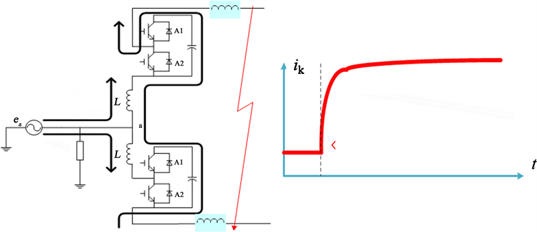
Figure 1. Fault current of a typical DC distribution system.
DC fault current suppression in the DC distribution system. At present, the research of the DC circuit breaker is still in the stage of theoretical research and prototype development, which can be divided into three types: the mechanical DC circuit breaker, the solid-state DC circuit breaker and the hybrid DC circuit breaker [12] - [16] . The DC current limiter can limit the large increase of the fault current after the DC fault occurs, and keep the fault current within the acceptable range, thus reducing the requirements for the operation time and capacity of DC circuit breaker to remove fault. It can be divided into three types: the fault current limiter based on superconducting material [17] , the fault current limiter based on positive temperature coefficient resistance [18] , and the fault current limiter based on power electronic devices [19] [20] . The converters with fault isolation are mainly for modular multilevel converters, which can be divided into: MMC based on full-bridge module and MMC based on clamped double-module [21] .
In summary, the existing research only proposes the topology structure and control method for the fault current suppression of a single device, and the existing research stays in the theoretical research and prototype development stage, and lacks extensive engineering application. In view of the fault characteristics of the DC power distribution system, in order to ensure that the DC power distribution system can operate normally under steady state and transient operation conditions, each current limiting device and the breaking device must cooperate with each other. However, since the DC power distribution system is still in the planning and development at home and abroad, and there is no literature and technical report on the collaborative configuration of the current limiting equipment and the current breaking equipment in the DC distribution system.
In view of the above situation, this paper studies the collaborative configuration of the DC circuit breaker and the DC current limiter suitable for the DC power distribution system. Firstly, based on the circuit model, the fault current suppression mechanism of the DC power distribution system is revealed. Then, based on the mathematical model of the DC breaker, the characteristic parameters of DC breaking are extracted, and then the influence of different characteristic parameters on the breaking characteristics of fault current is studied. Lastly, the mathematical model of the collaborative process between DC circuit breaker and DC current limiter is established, and the characteristic parameters of fault current collaborative suppression are extracted. The coupling effects of different characteristics parameters on fault current suppression and breaking are studied. The principle of the collaborative configuration of the DC current breaker and the DC current limiter is put forward, so as to fully excavate the collaborative suppression ability.
2. Fault Current Suppression Mechanism
When the MMC is in the unblocked mode, the current flowing from the MMC to the fault point is unipolar. To limit this unipolar current, there are two main ways [22] :
1) Resistive current limiting: A large resistor is connected in the fault current path, and the peak value of the fault current is limited by a resistor, such as a resistive superconducting current limiter.
2) Inductive current limiting: A large inductor is connected in the fault current path, and the rising rate of the fault current is limited by the inductor, such as a saturated reactance type current limiter.
There are two main ways to reduce this unipolar current to zero:
1) Insert an infinite resistance (i.e., the arrester) in the fault current path. At this time, regardless of the value of the equivalent voltage source of the MMC, the fault current will drop to zero, such as a mechanical DC circuit breaker or a hybrid DC circuit breaker.
2) A capacitor is connected in the fault current path, so that the fault path is converted into an LC oscillating circuit, then the unipolar fault current becomes an alternating current, and the fault current is cut off when the first zero crossing point is obtained. Such as MMC based on the full bridge sub-module.
In summary, through the coordination of the DC current limiter and the DC circuit breaker, as shown in Figure 2, the fault current can be limited to a lower value, and then the lower fault current can be broke. This will reduce the difficulty of arc extinguishing and manufacturing of mechanical switches, reduce the dynamic overvoltage of the power electronic devices caused by breaking large current, and increase the interruption capacity. In the following section, the parameter collaborative configuration of the DC Circuit Breaker and the DC fault current limiter will be studied.
3. Analysis of DC Breaking
In this chapter, the mathematical model of the DC circuit breaker is established, and the characteristic parameters of DC breaking are extracted, and then the influence of different characteristic parameters of DC breaking on the breaking effect is studied.
3.1. Technical Solution of DC Circuit Breaker
In this paper, an infinite resistance is introduced into the fault current path to realize current breaking. The typical examples are mechanical DC circuit breaker and hybrid DC circuit breaker, as shown in Figure 3.

Figure 2. Circuit model for coordination of fault current suppression devices.
For a mechanical DC circuit breaker, when a fault occurs, the mechanical switch K is opened. When the contact opening distance reaches a certain distance, the solid state switch S is turned on, and the resonant current generated by the LC oscillation branch is superimposed on the mechanical switch branch. Then the arc of the mechanical switch K is extinguished, the fault current is transferred to the LC oscillation branch; when the mechanical switch is opened and the gap can withstand the corresponding transient recovery voltage, the solid-state switch S is turned off; the voltage across the oscillation branch exceeds the action value of Metal Oxide Varistor (MOV), the fault current is transferred to the MOV branch, so that the MOV is connected in the fault path.
For the hybrid DC circuit breaker, when a fault occurs, the power electronic switch T is turned on firstly, and then the fast mechanical switch K is open. When the contact opening distance reaches a certain distance, the control switch of the coupled negative voltage circuit is triggered, and the current of the mechanical switch branch is transferred to the power electronic switch branch, the arc of the mechanical switch is extinguished; when the contact gap can withstand the corresponding transient recovery voltage, the power electronic switch T is turned off; at this time, the overvoltage generated by the branch will exceed the action value of the MOV, so that the MOV is turned on, and the MOV is serially connected in the fault path.
It can be seen from the above that the mechanical DC circuit breaker and the hybrid DC circuit breaker are only different in the current-commutation mode. After the DC circuit breaker completes the current-commutation, an infinite resistor (referred to as MOV) is connected in the fault current path. It is used to realize the breaking of the fault current and the absorption of the fault energy.
3.2. Mathematical Model of DC Circuit Breaker
When the DC circuit breaker completes the current-commutation and an infinite resistor is connected to the fault current path, the equivalent circuit model for the DC breaker to break the DC fault current is shown in Figure 4. Among, the circuit model ignores the line resistance, is the fault current, and is the voltage across the MOV, L is the equivalent inductance of the DC fault current path.

Figure 3. Two typical DC fault current breaking methods. (a) The mechanical DC circuit breaker; (b) The hybrid DC circuit breaker.

Figure 4. Equivalent circuit model for the DC breaker to break the DC fault current.
Assume that the instant when a MOV of the DC is inserted into the fault current path as the time starting point, namely , and the DC fault current is equal to the initial current value . When , then
, (1)
where, depends on the characteristics of MOV. Here, the volt-ampere characteristics of MOV are expressed by two piecewise broken lines, and then . Where, is , usually takes a value of 1.2; is the reference voltage of MOV; is the rated DC grid voltage; is the incremental resistance of MOV, and the smaller the value, the better the overvoltage protection characteristic of MOV. Further, the formula (1) can be changed to
. (2)
Solving Equation (2) gives:
. (3)
Assume that , , , , , then the curves of and as a function of time are shown in Figure 5.
As seen from the above figure, when the power electronic switch T is turned off, the overvoltage generated by the branch will exceed the action value of the MOV, then the MOV is serially connected to the circuit, the DC fault current and the voltage across the MOV reach a maximum value, and then gradually decrease; after the current crosses zero, the voltage across the MOV is abruptly changed to a rated DC voltage. This is because when the fault occurs, the fault current is broken by the circuit breaker, and the MMC is not blocked.
According to the mathematical model of DC breaking, that is, Equation (3), , , , are characteristic parameters that affect the breaking characteristics. In the next chapter, we will use the univariate change analysis method to analyze the influence of the change of characteristic parameters on and .
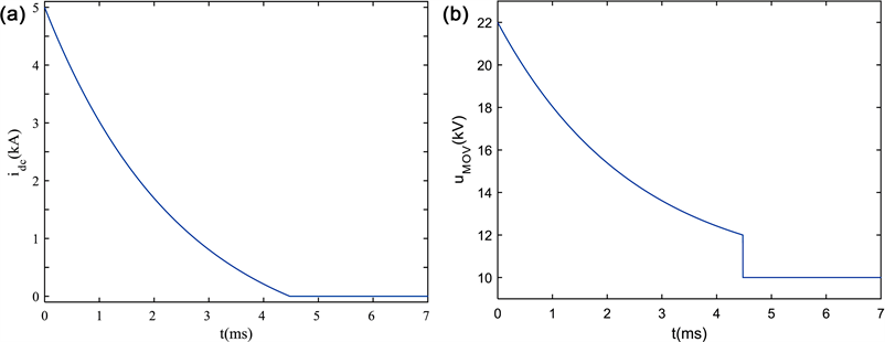
Figure 5. Curve of DC fault current and voltage across MOV. (a) DC fault current curve; (b) Voltage variation curve across MOV.
4. Parameter Configuration of DC Circuit Breaker and DC Current Limiter
This chapter will combine the mathematical model of DC circuit breaker and DC current limiter to establish the mathematical model of the coordination process between DC circuit breaker and DC current limiter, and extract the characteristic parameters of fault current collaborative suppression. The coupling effects of different characteristic parameters on fault current suppression are studied, and the principle of parameter collaborative configuration between DC circuit breaker and DC current limiter is proposed.
4.1. Mathematical Model of Collaborative Configuration
When a short circuit fault occurs, a resistance-type current limiter is connected to the fault current path. Then, DC circuit breaker starts to break fault current. After the DC circuit breaker completing the current-commutation, an infinite resistor is connected to the fault current path. The equivalent circuit model for the DC breaking and current limiting is shown in Figure 6. Among, R is the equivalent resistance of the DC current limiter.
Assume that the instant when a MOV of the DC is inserted into the fault current path as the time starting point, namely , and the DC fault current is equal to the initial current value . When , then
. (4)
Similarly, the volt-ampere characteristic of the MOV is represented by two segmented polylines, and the Equation (4) can be changed to
. (5)
Solving Equation (5) gives:
. (6)
Assume that , , , , , , then the curves of and as a function of time are shown in Figure 7.
It can be seen from the above figure that when the MOV is serially connected to the circuit, the DC fault current and the voltage across the MOV reach a maximum value, and then gradually decrease; after the current crosses zero, the voltage across the MOV is abruptly changed to a rated DC voltage. Compared with the fault current breaking with only MOV, when the resistance-type current limiter is matched with the MOV, the time required for the DC fault current to reach zero decreases, but the maximum value of the voltage across the MOV remains unchanged.
According to the mathematical model of collaborative configuration of DC circuit breaker and current limiter, that is, Equation (6), , , , , are characteristic parameters that affect the breaking characteristics. In the next chapter, we will use the univariate change analysis method to analyze the influence of the change of characteristic parameters on and .

Figure 6. Equivalent circuit model for the DC breaking and current limiting.
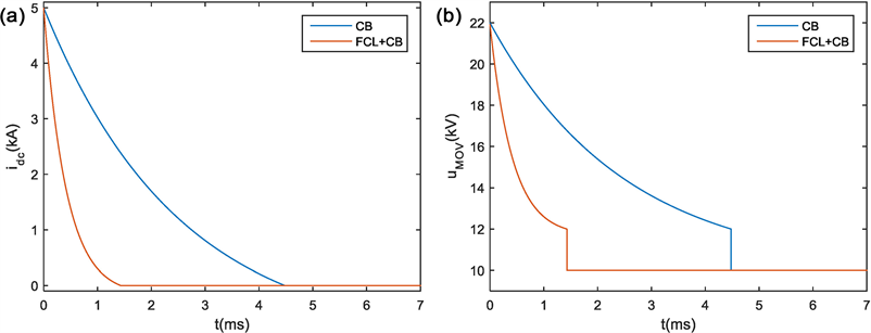
Figure 7. Curve of DC fault current and voltage across MOV. (a) DC fault current curve; (b) Voltage variation curve across MOV.
4.2. Sensitivity Analysis of Characteristic Parameters
1) Influence of R on breaking characteristics
For the mathematical model of collaborative configuration of DC circuit breaker and current limiter, the value of R is set to 1 Ω, 5 Ω, 10 Ω, 15 Ω and 20 Ω respectively, and other characteristic parameters are , , , , , then the characteristic curve of and with R can be obtained as shown in Figure 8.
It can be seen from the above figure that decreases with the increase of R, and the value of has nothing to do with R.
2) Influence of L on breaking characteristics
For the mathematical model of collaborative configuration of DC circuit breaker and current limiter, the value of L is set to 2 mH, 4 mH, 6 mH, 8 mH and 10 mH respectively, and other characteristic parameters are , , , , . Then the characteristic curve of and with L can be obtained as shown in Figure 9.
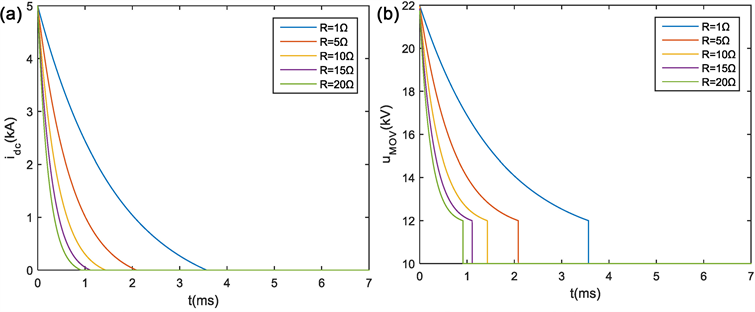
Figure 8. Curve of DC fault current and voltage across MOV. (a) DC fault current curve; (b) Voltage variation curve across MOV.

Figure 9. Curve of DC fault current and voltage across MOV. (a) DC fault current curve; (b) Voltage variation curve across MOV.
It can be seen that increases with the increase of L, and the value of has nothing to do with L.
3) Influence of R0 on breaking characteristics
For the mathematical model of collaborative configuration of DC circuit breaker and current limiter, the value of R0 is set to 1 Ω, 2 Ω, 3 Ω, 4 Ω and 5 Ω respectively, and other characteristic parameters are , , , , . Then the characteristic curve of and with R0 can be shown in Figure 10.
It can be seen that decreases as R0 increases, and the value of increases as R0 increases, which is different from the influence of R on .
4) Influence of Kref on breaking characteristics
For the mathematical model of collaborative configuration of DC circuit breaker and current limiter, the value of Kref is set to 1.1, 1.2, 1.3, 1.4 and 1.5 respectively, and other characteristic parameters are , , , , . Then the characteristic curve of and with Kref can be obtained as shown in Figure 11.
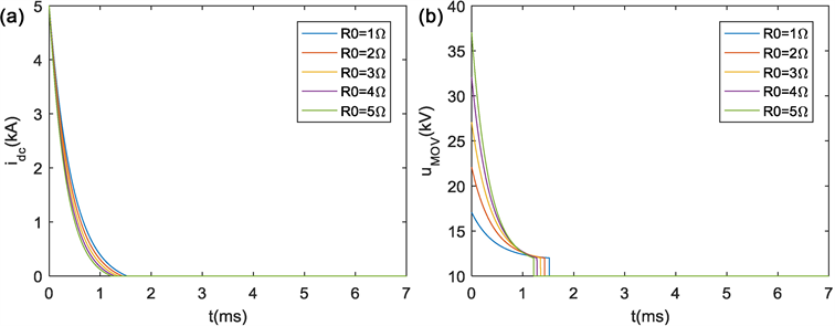
Figure 10. Curve of DC fault current and voltage across MOV. (a) DC fault current curve; (b) Voltage variation curve across MOV.

Figure 11. Curve of DC fault current and voltage across MOV. (a) DC fault current curve; (b) Voltage variation curve across MOV.
It can be seen that decreases as Kref increases, and increases as Kref increases.
5) Influence of idc0 on breaking characteristics
For the mathematical model of collaborative configuration of DC circuit breaker and current limiter, the value of idc0 is set to 2 kA, 24 kA, 6 kA, 8 kA and 10 kA respectively, and other characteristic parameters are , , , , . Then the characteristic curve of and with idc0 can be obtained as shown in Figure 12.
It can be seen from the above figure that idc increases as idc0 increases, and the value of increases as idc0 increases.
In summary, the fault characteristics of the system are greatly affected by the fault current (idc0) and the MOV parameters (R0, Kref ).
4.3. Principle of Parameter Collaborative Configuration
Based on the sensitivity analysis of the characteristic parameters of the collaborative cooperation between the DC circuit breaker and the DC current limiter, the parameter configuration is shown in Table 1. “↑” stands for enlargement, “↓” stands for decrease, “→” stands for unchanged.
It can be seen from the above table that, from the limit of , the larger the equivalent resistance R of the DC current limiter, the shorter the time , but the larger the R, the higher the manufacturing cost and volume will be, which

Table 1. Collaborative cooperation between the DC circuit breaker and the DC current limiter.

Figure 12. Curve of DC fault current and voltage across MOV. (a) DC fault current curve; (b) Voltage variation curve across MOV.
needs to be considered comprehensively. From the point of limiting , the smaller the equivalent inductance L of fault current path, the better; but from the point of limiting the rise rate of fault current di/dt, the larger the L, the better, which needs to be considered comprehensively. Larger and are beneficial to reduce , but increase , which needs to be considered comprehensively. To sum up, the collaborative configuration of DC circuit breaker and current limiter should take into account the magnitude of fault current, the rise rate of fault current, the volume and cost of equipment, and then the collaborative suppression ability of DC circuit breaker and DC current limiter to fault current can be fully exploited.
5. Conclusions
This paper studies the collaborative configuration of DC circuit breaker and DC current limiter for the DC distribution system.
1) The fault current suppression mechanism of the DC power distribution system is revealed. The current limiting method is mainly divided into the resistive current limiting and the inductive current limiting. The current breaking is mainly divided into an infinite resistance in the fault current path and a capacitor in the fault current path.
2) Based on the mathematical model of the DC circuit breaker, the characteristic parameters of DC breaking are extracted, namely , , , . Then the univariate variation method is used to study the influence of characteristic parameter changes on breaking characteristics and .
3) The mathematical model of the coordination process between the DC circuit breaker and the DC current limiter is established, and the characteristic parameters of the fault current collaborative suppression are extracted, namely , , , , . The influence of characteristic parameters on the fault current suppression and breaking is obtained. The principle of parameters collaborative configuration of DC circuit breaker and DC current limiter is proposed. Through research, the collaborative suppression ability of DC circuit breaker and DC current limiter to fault current is fully explored to ensure the safe and reliable operation of DC power distribution system.
Acknowledgements
This work is supported by National Key Research and Development Program 2017YFB0902304 and Science and Technology Program of China Southern Power Grid GDKJXM20172171.
Conflicts of Interest
The authors declare no conflicts of interest regarding the publication of this paper.
Cite this paper
Qu, L., Yu, Z.Q. and Yuan, Z.C. (2019) Research on Parameter Collaborative Configuration of DC Circuit Breaker and DC Fault Current Limiter. Journal of Power and Energy Engineering, 7, 80-93. https://doi.org/10.4236/jpee.2019.79006
References
- 1. Baran, M.E. and Mahajan, N.R. (2003) DC Distribution for Industrial Systems: Opportunities and Challenges. IEEE Transactions on Industry Applications, 39, 1596-1601. https://doi.org/10.1109/TIA.2003.818969
- 2. Riccobono, A. and Santi, E. (2014) Comprehensive Review of Stability Criteria for DC Power Distribution Systems. IEEE Transactions on Industry Applications, 50, 3525-3535. https://doi.org/10.1109/TIA.2014.2309800
- 3. Jiang, D. and Zheng, H. (2012) Research Status and Developing Prospect of DC Distribution Network. Automation of Electric Power Systems, 36, 98-104.
- 4. Starke, M.R., Li, F., Tolbert, L.M. and Ozpineci, B. (2008) AC vs. DC Distribution: Maximum Transfer Capability. 2008 IEEE Power and Energy Society General Meeting, Pittsburgh, PA, 20-24 July 2008, 1-6. https://doi.org/10.1109/PES.2008.4596730
- 5. Dastgeer, F. and Kalam, A. (2009) Efficiency Comparison of DC and AC Distribution Systems for Distributed Generation. 2009 Australasian Universities Power Engineering Conference, Adelaide, SA, 27-30 September 2009, 1-5.
- 6. Salomonsson, D., Soder, L. and Sannino, A. (2009) Protection of Low-Voltage DC Microgrids. IEEE Transactions on Power Delivery, 24, 1045-1053. https://doi.org/10.1109/TPWRD.2009.2016622
- 7. Yang, J., Fletcher, J.E. and O’Reilly, J. (2010) Multiterminal DC Wind Farm Collection Grid Internal Fault Analysis and Protection Design. IEEE Transactions on Power Delivery, 25, 2308-2318. https://doi.org/10.1109/TPWRD.2010.2044813
- 8. Yang, J., Fletcher, J.E. and O’Reilly, J. (2012) Short-Circuit and Ground Fault Analyses and Location in VSC-Based DC Network Cables. IEEE Transactions on Industrial Electronics, 59, 3827-3837. https://doi.org/10.1109/TIE.2011.2162712
- 9. Tang, L. and Ooi, B.T. (2007) Locating and Isolating DC Faults in Multi-Terminal DC Systems. IEEE Transactions on Power Delivery, 22, 1877-1884. https://doi.org/10.1109/TPWRD.2007.899276
- 10. Baran, M.E. and Mahajan, N.R. (2007) Overcurrent Protection on Voltage-Source-Converter-Based Multiterminal DC Distribution Systems. IEEE Transactions on Power Delivery, 22, 406-412. https://doi.org/10.1109/TPWRD.2006.877086
- 11. Cuzner, R.M. and Venkataramanan, G. (2008) The Status of DC Micro-Grid Protection. 2008 IEEE Industry Applications Society Annual Meeting, Edmonton, 5-9 October 2008, 1-8. https://doi.org/10.1109/08IAS.2008.382
- 12. Franck, C.M. (2011) HVDC Circuit Breakers: A Review Identifying Future Research Needs. IEEE Transactions on Power Delivery, 26, 998-1007. https://doi.org/10.1109/TPWRD.2010.2095889
- 13. Tahata, K., Oukaili, S.E., Kamei, K., et al. (2015) HVDC Circuit Breakers for HVDC Grid Applications. 11th IET International Conference on AC & DC Power Trans-mission, Birmingham, 10-12 Feburary 2015. https://doi.org/10.1049/cp.2015.0018
- 14. Cwikowski, O., Chang, B., Barnes, M., et al. (2016) Fault Current Testing Envelopes for VSC HVDC Circuit Breakers. IET Generation, Transmission & Distribution, 10, 1393-1400. https://doi.org/10.1049/iet-gtd.2015.0863
- 15. Bachmann, B., Mauthe, G., Ruoss, E., et al. (1985) Development of a 500kV Airblast HVDC Circuit Breaker. IEEE Transactions on Power Apparatus and Systems, PAS-104, 2460-2466. https://doi.org/10.1109/TPAS.1985.318991
- 16. Wang, X., Wen, J., Peng, C., et al. (2012) Simulation and Test Research for DC Breakers of UHVDC Transmission System. 2012 Second International Conference on Intelligent System Design and Engineering Application, Sanya, Hainan, 6-7 January 2012, 1480-1485. https://doi.org/10.1109/ISdea.2012.725
- 17. Nemdili, S. and Belkhiat, S. (2012) Modeling and Simulation of Resistive Super-conducting Fault-Current Limiters. Journal of Superconductivity & Novel Magnetism, 25, 2351-2356. https://doi.org/10.1007/s10948-012-1685-z
- 18. Guo, Z., Sun, H., Bai, B. and Dong, X.B. (2010) Experiment and Simulation of PTC Used in Fault Current Limiter. CICED 2010 Proceedings, Nanjing, 13-16 September 2010, 1-9.
- 19. Chen, G., Jiang, D., Lu, Z. and Wu, Z. (2004) A New Proposal for Solid State Fault Current Limiter and Its Control Strategies. 2004 IEEE Power Engineering Society General Meeting, Denver, CO, 6-10 June 2004, 1468-1473.
- 20. Bourne, J., Schupbach, M., Carr, J., H. Mantooth, A. and Balda, J. (2009) Initial Development of a Solid-State Fault Current Limiter for Naval Power Systems Protection. 2009 IEEE Electric Ship Technologies Symposium, Baltimore, MD, 20-22 April 2009, 491-498. https://doi.org/10.1109/ESTS.2009.4906557
- 21. Schmitt, D., Wang, Y., Weyh, T. and Marquardt, R. (2012) DC-Side Fault Current Management in Extended Multiterminal-HVDC-Grids. International Multi-Conference on Systems, Signals & Devices, Chemnitz, Germany, 20-23 March 2012, 1-5. https://doi.org/10.1109/SSD.2012.6198125
- 22. Zheng, X., Xiao, H. and Xu, Y.Z. (2019) Two Basic Ways to Realise DC Circuit Breakers. The Journal of Engineering, 16, 3098-3105. https://doi.org/10.1049/joe.2018.8760