Journal of Electromagnetic Analysis and Applications
Vol. 1 No. 4 (2009) , Article ID: 1115 , 7 pages DOI:10.4236/jemaa.2009.14034
Principle and Characteristic of Lorentz Force Propeller
![]()
Northwest Polytechnical University, Xi’an, Shaanxi, China.
Email: zhujing21@sina.com
Received August 4th, 2009; revised September 1st, 2009; accepted September 9th, 2009.
Keywords: Electric Field, Magnetic Field, Self-Field, Radiation Field, the Lorentz Force
ABSTRACT
This paper analyzes two methods that a magnetic field can be generated, and classifies them under two types: 1) Self-field: a magnetic field can be generated by electrically charged particles move, and its characteristic is that it can’t be independent of the electrically charged particles. 2) Radiation field: a magnetic field can be generated by electric field change, and its characteristic is that it independently exists. Lorentz Force Propeller (ab. LFP) utilize the characteristic that radiation magnetic field independently exists. The carrier of the moving electrically charged particles and the device generating the changing electric field are fixed together to form a system. When the moving electrically charged particles under the action of the Lorentz force in the radiation magnetic field, the system achieves propulsion. Same as rocket engine, the LFP achieves propulsion in vacuum. LFP can generate propulsive force only by electric energy and no propellant is required. The main disadvantage of LFP is that the ratio of propulsive force to weight is small.
1. Introduction
The magnetic field generated by a changing electric field is a kind of radiation field and it independently exists. When the moving electrically charged particles are subjected to Lorentz force in the magnetic field, the device generating the changing electric field isn’t subjected to any reacting force.
2. Theoretical Basis
As we know, a magnetic field can be generated by two methods: one is electrically charged particles move and the other is electric field change [1]. However, the magnetic fields generated by the two methods are entirely different in nature.
We discuss the magnetic field generated by moving electrically charged particles at first. It’s well known that the electric quantity carried by the electrically charged particles isn’t affected by the motion state of the particles. This shows that when the electrically charged particles generate a magnetic field due to their movement, the electric quantity owned by the particles doesn’t change with the generation of the magnetic field. Only the distribution of the electric energy, i.e., the distribution of the electric field, is affected by the motion state of the particles. (We will mention below that even this change is also due to the changes in observation angle.) “If the electric quantity carried by the particles is certain, the magnetic field generated by the particles is entirely determined by the motion speed of the particles” [2] and it is a single-valued function of the motion speed. In other words, there must be a certain magnetic field corresponding to the electrically charged particles when the motion state of the particles is determined. This suggests that the magnetic field generated by the moving electrically charged particles is the state quantity which describes the motion state of the electrically charged particles. The state quantity, which reflects the sate of a physical object, is different in different reference systems, but it can’t be separated from the physical object and can’t be independent of the physical object. Thus, the magnetic field generated by moving electrically charged particles is different in different reference systems. Of cause the magnetic field can’t be independent of the electrically charged particles and it’s the self-field of the particles.
As the magnetic field generated by moving electrically charged particles, kinetic energy also belongs to state quantity. They reflect the motion state of a physical object in the form of energy. The difference between them is as follows. The motion state of a physical object is described by its mass in kinetic energy, which is centralized at the object. The motion state of the electrically charged particles is described by the electric quantity in the magnetic field, which is generated by the moving particles and distributed in the space around the particles.
Then we discuss the magnetic field generated by a changing electric field. Based on the energy conservation principle, the total energy in the electromagnetic field isn’t changed in the course that a magnetic field is generated by a changing electric field. This indicates that the magnetic energy is continuously generated and the electric energy is continuously decreased at the same time. The magnetic energy is transformed from the decreased electric energy. The course that a magnetic field is generated by a changing electric field is a course that electric energy is transformed into magnetic energy. The electric energy and the magnetic energy are localized in the electric field and the magnetic field respectively. According to “the superposition principle of electric fields” [3], the initial electric field can be regarded as the superposition of two mutually independent electric fields in the above-mentioned course at any time. One of the two electric fields is the electric field with the localized electric energy, which has been transformed into magnetic energy. The other is the electric field with the localized electric energy, which hasn’t been transformed into magnetic energy. Obviously, the former electric field generated a magnetic field but the magnetic field has disappeared. The latter electric field still exists but it hasn’t generated any magnetic field. Because the two electric fields are mutually independent, the magnetic field generated by the former electric field is independent of the latter electric field. In other words, the magnetic field and the electric field are mutually independent in the course that the magnetic field is generated by the changing electric field. The former electric field is also a tie between the magnetic field and the device generating the changing electric field and it’s shown as the device generating the changing electric field → the electric field → the magnetic field. With the disappearance of the former electric field, the magnetic field generated by the changing electric field is not only independent of the electric field, but also independent of the device generating the changing electric field at the same time. The changing electric field and the device generating the changing electric field are only the initial condition to generate a magnetic field. The magnetic field generated by the changing electric field is a radiation field and it’s irrelevant to reference system.
The relation between the magnetic field generated by a changing electric field and the device generating the changing electric field is similar to the relation between electromagnetic waves and an antenna. The antenna is only the initial condition to generate electromagnetic waves. When the electromagnetic waves have been generated, they are irrelevant to the antenna. In other words, the electromagnetic waves are separated from the antenna and independent of the antenna. [4]
It’s another issue that a changing magnetic field also generates an electric field, which is known as the issue that magnetic energy is transformed into electric energy. Similarly, the electric field generated by the changing magnetic field is independent of the magnetic field. “A magnetic field is generated by a changing electric field, and an electric field is generated by the changing magnetic field” [5], so repeatedly. The process is continuously repeated. The most common example is electromagnetic waves. Just because not only the magnetic field generated by a time varying electric field but also the electric field generated by the time varying magnetic field is a radiation field, electromagnetic waves are formed and spread continuously. On the surface, the electric field and the magnetic field in the electromagnetic waves are tightly fastened and linked. But in fact, they are mutually independent and irrelevant to each other.
The law of a time varying electromagnetic field follows the Maxwell equation. “The differential form of the Maxwell equations in free space is given as follows [6]
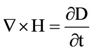
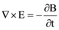
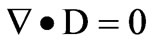
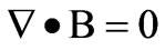 ”
”
It can be seen from the equations that the size of the magnetic field intensity is determined by the changing rate of the electric field. However, according to the above-mentioned, the magnetic field is transformed from the disappeared electric field, so the size of the magnetic field intensity should be determined by the changing amount of the electric field. They seem to be contradictory. This is because that the two courses that the time varying electric field generates the magnetic field and the time varying magnetic field generates the electric field occur at the same time, rather than the magnetic field begins to transform into the electric field after the electric field has thoroughly transformed into the magnetic field. It can be seen more easily from electromagnetic waves.
Finally, we discuss the different changes in the electric field when the electrically charged particles have different motion speeds or have acceleration. The relations between the changes and electromagnetic radiation are also investigated.
The situation that the electrically charged particles have different motion speeds is firstly discussed. As shown in Figure 1, a is a stationary particle carrying positive charge and its electric field is distributed in the space
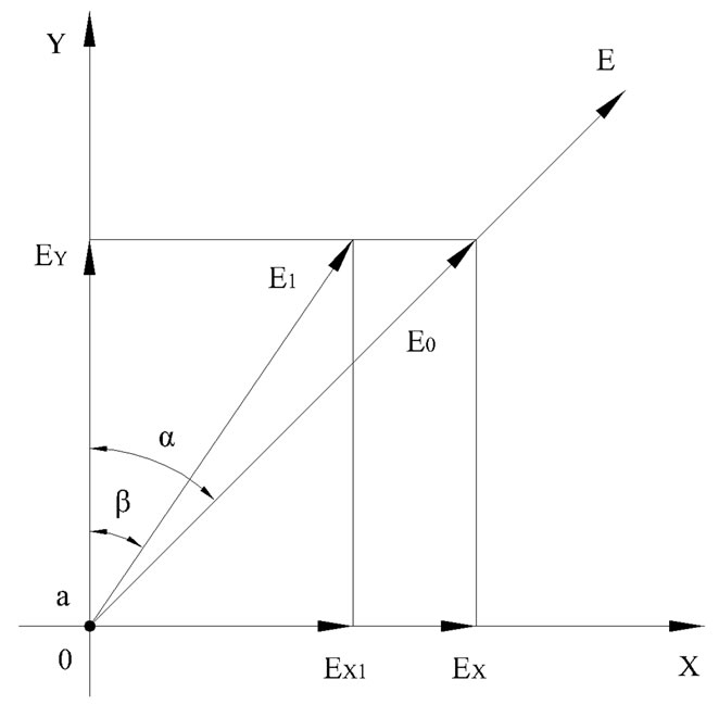
Figure 1. The reason for the deflection of the electric field line
around it. An arbitrary electric field line, E, is chosen and discussed. It’s supposed that the angle between the electric field line, E, and the Y-axis is α. A certain part of the electric field line, called E0, which starts from the particle, is randomly intercepted from E. The electric field line E0 is decomposed into two mutually perpendicular components. One, called EX, is parallel to the X-axis. The other, called EY, is parallel to the Y-axis. When the electrically charged particle, a, moves in a straight line with a uniform speed along the X-axis direction, the length of EX is shortened because it’s parallel to the motion direction, shown as EX1. The phenomenon is known as Lorentz contraction. Nevertheless, the length of EY is unchanged because it’s perpendicular to the motion direction. It can be seen from Fig.1 that the vector sum of EX1 and EY is no longer E0 but E1. The angle between E1 and the Y-axis is β and β <α is satisfied. This means that the electric field line is deflected towards the Y-axis and the particle is the circle center. So the distribution of the electric field changes. The faster the motion speed of the particle is, the larger the Lorentz contraction is. Thus the deflection of the electric field line is more obvious. In practice, an electric field line starts from a positive charge and ends at a negative charge. So we can only observe the deflection of the electric field line, rather than observe the Lorentz contraction. In Figure 1, the length of EX is shortened caused by the Lorentz contraction, but its inherent length is unchanged. So the “inherent angle” between the electric field line and the Y-axis is unchanged and the “inherent distribution” of the electric field is also unchanged. From the above-mentioned, it’s conduced that the change of the electric field of the electrically charged particles caused by the different motion speeds of the particles is the relative change between electrically charged particles and reference system in essence. Therefore, the magnetic field generated by the moving electrically charged particles aren’t generated by the change of the electric field. Electrically charged particles moving in a straight line with a uniform speed can’t generate any electromagnetic radiation.
“The electric field of stationary electrically charged particles and the electric field of electrically charged particles moving in a straight line with a uniform speed are both radial. The electric field lines of them are also straight” [7] and the inherent distributions of them are also the same. This state of the electric field of the particles is called a normal state. When the electrically charged particles have acceleration, the electric fields of the particles are no longer radial and a horizontal component perpendicular to the radial direction will emerge in the electric field. The horizontal component is irrelevant to the motion speed of the particles and it’s determined by the accelerations of the particles. Therefore, the inherent distribution of the electric field changes. According to the superposition principle of electric fields, the horizontal component and the radial component can be regarded as two mutually independent electric fields. And they are known as the horizontal electric field and the radial electric field. Then they are respectively discussed below.
No matter how the motion speed of the electrically charged particles changes, the electric field of the particles is in a normal state. This indicates that the changing electric field caused by the acceleration of the electrically charged particles tends to return to a normal state. In other words, the horizontal electric field tends to disappear. The disappeared horizontal field will generate a magnetic field, that is, a changing electric field generates a magnetic field, and the electrically charged particles generate electromagnetic radiation. When the acceleration of the electrically charged particles remains unchanged or increases, the horizontal electric field doesn’t decrease or disappear, and it remains unchanged or increases on the contrary. At the same time, the electromagnetic radiation still exists. It seems incompatible with the opinion that a magnetic field is generated while an electric field disappears. The reason is that an external force (because the electrically charged particles have acceleration) and the electromagnetic radiation act simultaneously. The external force keeps the horizontal electric field increasing continuously and the electric field lines bending continuously at the same time. The electromagnetic radiation keeps the horizontal electric field decreasing constantly and the electric field lines constantly returning to being straight. When the effect of the external force is equal to or in excess of the effect of the electromagnetic radiation, the increased horizontal electric field is equal to or in excess of the decreased horizontal electric field. At this time, the phenomenon that the electromagnetic radiation is continuously generated and the horizontal electric field keeps unchanged or increases appears.
The deflection of the radial electric field is caused by the change of the motion speed of the particles. As above-mentioned, it’s irrelevant to the generation of the radiation magnetic field, that is, it is irrelevant to the electromagnetic radiation.
We have got two conclusions that analyze the different origins of magnetic fields:
1) A magnetic field that can be generated by electrically charged particles move is the self-field of the particles, and it can’t be independent of the electrically charged particles.
2) A magnetic field can be generated by electric field change is radiation field, and it independently exists.
3. Operating Principle
The magnetic field generated by a changing electric field is a kind of radiation field and it independently exists. When the moving electrically charged particles are subjected to Lorentz force in the magnetic field, the device generating the changing electric field isn’t subjected to any reacting force. The Newton’s third law is not tenable between the electrically charged particles and the device generating the changing electric field.
The carrier of the moving electrically charged particles and the device generating the changing electric field are fixed together to form a system. The relative position between them makes the moving electrically charged particles is located in the magnetic field generated by the changing electric field and the motion direction of the electrically charged particles is unparallel to the direction of the magnetic field. The magnetic field generated by the changing electric field is independent of the device generating the changing electric field, so it’s independent of the foregoing system. For the foregoing system, the Lorentz force subjected by the moving electrically charged particles in the magnetic field generated by the changing electric field is attributable to a external force of the system. When the carrier of the electrically charged particles moves under the action of the Lorentz force, the device generating the changing electric field is driven and moves together with the carrier. Thus, the system achieves propulsion. The above-mentioned is the design idea of the new novel propulsion system. The new propulsion system utilizes Lorentz force, so it’s called as the Lorentz force propeller, which is LFP for short hereinafter.
Obviously, conductor can be selected as the carrier of the moving electrically charged particles. Yet, what kind of devices can be used to generate a radiation magnetic field?
The most common radiation magnetic field is the magnetic field in electromagnetic waves. That is to say that an antenna is the most common device being able to generate a radiation magnetic field. But there are two main problems if an antenna is selected as the device generating a radiation magnetic field. One is that it’s difficult to improve the magnetic induction intensity, which is crucial to improve the propulsion force. The other is that it will produce electromagnetic radiation pollution. So we have to find a new way to solve these problems. A coil (solenoid) is selected as the device to generate a changing electric field.
When we talk about a coil, i.e., inductance, we generally consider that “the energy of the inductance is stored in the magnetic field generated by the current.” [8] How is the energy stored in the inductance? For easily discussed, we suppose that the coil is ideal, that is, it hasn’t internal resistance.
As we all know, “when a time varying current flows through a coil, a magnetic field is generated in the coil and an induced electric field is generated in the coil winding” [9]. Generally, the induced electric field is also time varying. At a steady state, the induced electric field can’t generate any current because it’s disturbed by an external electric field. The changing induced electric field will generate a magnetic field. How can we know this? It has been known that the inductive reactance of the coil increases and the current decreases if other conditions are unchanged and only the frequency of the time varying current increases. The limit case that the frequency approaches infinity is assumed. In this case, the inductance is broken, no current flows through the coil and the induced electric field reaches the maximum. There is no current means that there is no energy input or output. At this time, the energy stored in the inductance should be a definite value. But the induced electric field is time varying. Where is the energy gone when the induced electric field decreases? Where is the energy from when the induced electric field increases? The answer is that the time varying induced electric field generates a time varying magnetic field. The energy is transformed backwards and forwards between the electric field and the magnetic field, and the total energy of the electromagnetic field remains unchanged.
In general, when a time varying current flows through a coil, two magnetic fields are generated in the coil. One is the magnetic field generated by the current, that is, the magnetic field generated by the moving electrically charged particles. The other is the magnetic field generated by the induced electric field, that is, the magnetic field generated by the changing electric field. The two magnetic fields are superposed.
Therefore, it can be deduced from the abovementioned that the energy stored in the inductance should include three parts: the magnetic field generated by the current, the induced electric field and the magnetic field generated by the induced electric field. The first part of the energy will flow into and out of the inductance together with the current. When it reaches a steady state, the other two parts of the energy is always stored in the coil.
If the frequency of the current is zero, that is, the current is a direct current, the induced electric field is zero and only the magnetic field generated by the current exists in the coil. With the increase of the frequency of the current, the current gradually decreases and the magnetic field generated by the current also gradually decreases. At the same time, the induced electric field gradually increases and the magnetic field generated by the induced electric field also gradually increases. When the frequency of the current approaches infinity, the current disappears and the magnetic field generated by the current also disappears. At the same time, the induced electric field reaches the maximum and the magnetic field generated by the current also reaches the maximum. The magnetic field generated by the induced electric field is the magnetic field generated by the changing electric field and it is a kind of radiation field. This is the reason that the higher the frequency of a current is, the more powerful the radiation is. The number and magnitude of radiation magnetic fields isn’t the only factor forming electromagnetic waves. The generation of electromagnetic waves is also determined by the characteristics of the antenna.
As we all know, an antenna is not only a transmitting antenna, but also a receiving antenna. In other words, it can not only transmit electromagnetic waves, but also receive electromagnetic waves at the same time. In fact, an antenna shows the characteristics of transmitting and receiving simultaneously when it transmits electromagnetic waves. When it generates a radiation magnetic field, the antenna will receive them back more or less at the same time. The received part forms electromagnetic induction and the unreceived part forms electromagnetic waves. [10]
Strictly speaking, the magnetic field generated by the induced electric field shouldn’t be regarded as the energy stored in the coil because it is a kind of radiation field and is independent of the coil. The magnetic field is generated by the coil and received by the coil in turn. From this point of view, the coil can be regarded as an antenna. The phenomenon that a coil receives its own radiation magnetic field is called self-induction of the coil. Moreover, the receiving is not necessarily 100%, for example, inducing mutually in the coil or radiating electromagnetic waves.
As shown in Figure 2, the conductor I0 gets through the coil L0, and they are fixed together and form a system. a is the main view and b is the left view. When there are time varying currents flowing through the conductor I0
and the coil L0 respectively, the moving electrically charged particles in the conductor I0 are located in the magnetic field generated by the coil L0 and their directions are unparallel. The conductor I0 will be subjected to two Lorentz forces. One is the acting force that the cur-
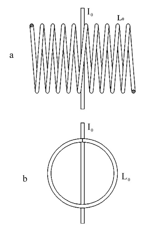
Figure 2. The operating principle of Lorentz Force Propeller
rent-carrying conductor is subjected in the magnetic field generated by the current and the other is the acting force that it is subjected in the magnetic field generated by the induced electric field. For the above-mentioned system, the former acting force is an internal force of the system. Its reacting force is the Lorentz force that the coil winding is subjected in the magnetic field generated by the current-carrying conductor. Since the conductor I0 and the coil L0 are fixed together, the couple of acting force and reacting force can’t make any relative movement between the conductor I0 and the coil L0. So the relative position between them is also unchanged. The latter acting force is an external force of the system and it hasn’t any reacting force. When the current-carrying conductor I0 moves under the action of the force, the coil L0 will be driven and move together with the conductor. Therefore, the system achieves propulsion.
Because the direction of the magnetic field generated by the induced electric field is time varying, the current in the conductor I0 should also be time varying in order to achieve propulsion. The frequencies of them must be same, and the phase difference between them is 0 or 1/2 cycle. The direction of the propulsive force when the phase difference is zero is opposite to that of the propulsive force when the phase difference is 1/2 cycle. In addition, there is no magnetic core (iron core) in the coil L0. Since it’s generated by the moving electrically charged particles, the magnetic field doesn’t contribute to propulsion.
Like electric motor, LFP also utilizes the Lorentz force. But there are two fundamental differences between them.
1) Electric motor utilizes the magnetic field generated by electrically charged particles, whereas LFP utilizes the magnetic field generated by a changing electric field.
2) In electric motor, the current-carrying conductor and the device generating magnetic field can relatively move and they are called stator and rotor. In LFP, the current-carrying conductor and the device generating magnetic field are fixed and there is no relative movement between them.
Just because the foregoing differences, LFP and electric motor have completely different functions. Electric motor can’t achieve propulsion by itself and a propulsion device must be adopted. For example, cartwheels are used to achieve propulsion by the friction between cartwheels and the ground. So it can’t be called a propeller. LFP can achieve propulsion by itself and it can propel in vacuum.
4. Design Optimization
In the LFP shown in Figure 2, both of the two ends of the coil L0 are open, and the external of the coil may generate magnetic field. One part of the conductor I0 is in the coil and the other part is out of the coil. The directions of the two magnetic fields that the two parts are located are opposite. That is to say, the directions of the Lorentz forces subjected are also opposite. It’s harmful to propulsion. In addition, some other problems, such as radiation pollution and electromagnetic induction, may arise at the same time. In order to overcome these disadvantages, the LFP shown in Figure 2 is optimized and shown in Figure 3. In Figure 3, L1 is an end-to-end annular coil. I1~I6 are the six conductors getting through the coil Ll. They are divided into two layers. I1, I2 and I3 are located at the upper layer and I4, I5 and I6 are located at the lower layer. The two parts are fixed with the coil L1 respectively. F is the direction of the propulsion force.
L1 is a closed coil and the magnetic field in the external of the coil is eliminated. So the problem resulting from this disappears. It should be explained that because the direction of the magnetic field that the conductors I1, I2, I3 are located is opposite to the direction of the magnetic field that the conductors I4, I5, I6 are located, there is 1/2 cycle phase difference between the current in the conductors I1, I2, I3 and that in the conductors I4, I5, I6. Figure 3 is the schematic drawing. In practical application, the shape and turn number of coil, the number and position of conductors can be adjusted and determined according to different requirements.
It’s very important to manufacture propellers with large propulsive force in practice. To obtain more powerful propulsive force, the most intuitive method is to increase the amplitude and the frequency of the time varying current. However, it’s restricted by many factors, such as materials and manufacture techniques. Thus, the effect is limited. We conceive a new novel method to obtain large propulsive force, which is described as follows.
L2 is a helical closed coil, shown in Figure 4 a. It can also be considered that one end of the eight L1 is cut and then they are connected end to end. For simplicity, there are two conductors, I7 and I8, are shown in Figure 4 a. They get through the upper and lower layer of the coil respectively. The direction of the propulsive force is perpendicular to the paper.
The propulsive device shown in Figure 4 a can be fixed on a circular pedestal. Therefore, a propulsive unit, which looks like an optical disc in appearance, is obtained. Then many of these propulsive units are organically assembled, for example, stacked as shown in Figure4 b, to obtain more powerful propulsive force. In Figure 4(b), F is the direction of the propulsive force.
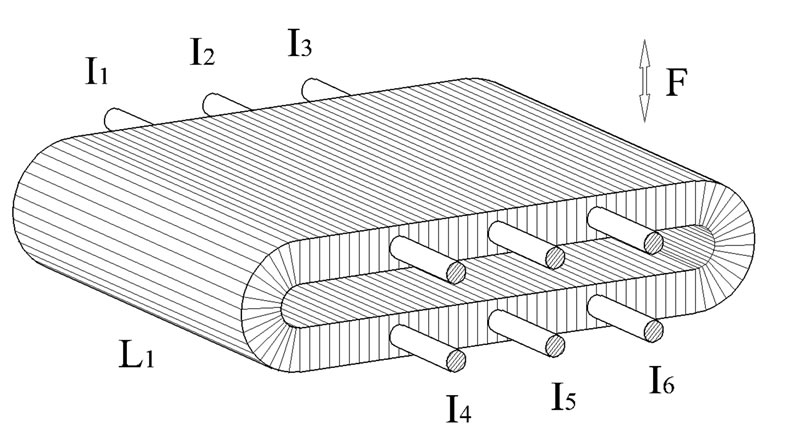
Figure 3. The three-dimensional schematic drawing of design optimization of Lorentz Force Propeller
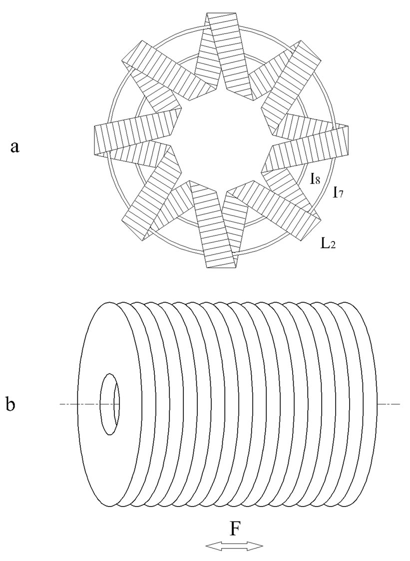
Figure 4. The schematic drawing of Lorentz Force Propeller with large propulsive force
5. Main Characteristics
An integrated Lorentz force propulsion system includes three main parts: energy supply system, control system and LFP. The function of the energy supply system is to supply electric energy for the whole system. It may be batteries, combustion engines, nuclear reactors and so on. The main function of the control system is to control the magnitude and the direction of the propulsive force by controlling the current inputting into the LFP. The function of the LFP is to transform electric energy into propulsive force. The energy supply system and the control system should be determined according to different concrete situations and requirements. With different selection, the two systems may be quite different. Therefore, only the characteristics of LFP are discussed in the paper and the integrated Lorentz force propulsion system isn’t involved. Moreover, because LFP is a new novel design, the studies on materials, manufacture techniques and so on related to LFP are blank. And these are the important factors determining the performance of LFP. Thus, only qualitative analysis on LFP is made and no quantitative analysis is done.
Like rocket engine, LFP can generate propulsive force without any external medium. So the main characteristics of LFP are described by the comparison with rocket engine.
1) LFP can generate propulsive force only by electric energy and no propellant is required.
2) The specific impulse of LFP is large. If solar energy or nuclear energy is used, the specific impulse may be astronomical. (The specific impulse is an important index to describe the performance of rocket engine through the assumption of propellant. LFP doesn’t use any propellant. For comparison, the assumption of propellant is replaced by the assumption of fuel here. In mechanical rocket engine, fuel has the same meaning as propellant.)
3) The propulsive force of liquid-propellant rocket engine can be adjusted in a certain range by adjusting the throttle and other mechanical components. The ratio of propulsive force can reach 10:1.
LFP can adjust propulsive force directly by controlling the current and no mechanical component is required. The adjusting accuracy and response speed are far superior to those of rocket engine. The adjusting range is between 0 and the maximum propulsive force. The ratio of propulsive force approaches infinity and the direction of propulsive force can be reversed 1800.
4) There is severe mechanical vibration when rocket engine is working. Although the propulsive force of LFP is time varying, there is no mechanical vibration because the frequency is high.
5) When LFP is working, no sound is produced and no exhaust gas is emitted. So it’s beneficial to protect environment.
6) Compared with rocket engine, the main disadvantage of LFP is that the ratio of propulsive force to weight is small.
6. Claims
LFP has been applied for a patent. So please do not use without permission.
REFERENCES
- B. S. Guru and H. R. Hiziroglu, “Electromagnetic field theory fundamentals,” (Second Edition) (Chinese Version), published by Cambridge University Press in 2005, P5, P7. There have expatiated generating methods of magnetic field.
- F. T. Ulaby, “Fundamentals of applied electromagnetics,” (Fourth Edition) (Chinese Version), 2004 Media Edition, 013185089X by ULABY, published by Pearson Education, Inc., P8.
- F. T. Ulaby, “Fundamentals of applied electromagnetics,” (Fourth Edition) (Chinese Version), 2004 Media Edition, 013185089X by ULABY, published by Pearson Education, Inc., P6.
- N. N. Rao, “Elements of engineering electromagnetics,” (Sixth Edition) (Chinese Version), published by Pearson Education, Inc., P427, P449, P450. There has expatiated the relation between electromagnetic waves and an antenna.
- B. S. Guru and H. R. Hiziroglu, “Electromagnetic field theory fundamentals,” (Second Edition) (Chinese Version), published by Cambridge University Press in 2005, P185, 2005.
- J. A. Edminister, “Schaum’s outlines theory and problems of electromagnetics,” Second Edition (Chinese Version), P148, 2002.
- B. S. Guru and H. R. Hiziroglu, “Electromagnetic field theory fundamentals,” (Second Edition) (Chinese Version), published by Cambridge University Press in 2005, P57.
- T. L. Floyd, “Principles of electric circuits: Conventional current, seventh edition,” (Chinese Version), published by Pearson Education, Inc., P430
- T. L. Floyd, “Principles of electric circuits: Conventional current version,” (Seventh Edition) (Chinese Version), published by Pearson Education, Inc., P429, P431
- B. S. Guru and H. R. Hiziroglu, “Electromagnetic field theory fundamentals,” (Second Edition) (Chinese Version), published by Cambridge University Press in 2005, P366, P386, P387. There has expatiated the course that antenna radiates electromagnetic waves.