Applied Mathematics
Vol.4 No.8(2013), Article ID:35146,17 pages DOI:10.4236/am.2013.48152
A Quantitative Computational Method for Landslip Orientation of a Body Isolated from Bed Rock in Mountain by Using Spatial Analytic Geometry
Mathematical College of Tianjin Normal University, Upāsaka (Viewer of Reality of Personality), Tianjin Dabei Buddhist Institute, Tianjin, China
Email: amritahcg@126.com
Copyright © 2013 Chenggui Huang. This is an open access article distributed under the Creative Commons Attribution License, which permits unrestricted use, distribution, and reproduction in any medium, provided the original work is properly cited.
Received May 17, 2013; revised June 18, 2013; accepted June 26, 2013
Keywords: Landslip Plane; Normalization of Horizontal Project; Un-Allowed Straight Angle Law; Critical Straight Angle Law; Allowed Straight Angle Law; Project Expression According to Unit Sphere
ABSTRACT
The paper is going to give a quantitative computational method for “Landslip Orientation of a body isolated from bed rock in Mountain” only with spatial analytic geometry. The paper gives computational formulae in proper order for only landslip plane, just two landslip planes and just three landslip planes, and gives numerical examples. And the paper gives a general computational model for landslip orientation of m landslip planes. The author puts forward “Un-allowed Straight Angle Law”, “Critical Straight Angle Law” and “Allowed Straight Angle Law”. Finally, the author gives a project expression of a landslip plane on unit sphere.
1. Introduction
In paper [1], Professor Shi Gen Hua found that the landslip of an isolated rock body is only able to produce along finite planes. If one parallel moves the finite planes passed through origin O, then he will find on the unite sphere centered O they form a polygon constructed by their up sides. Let S denote the lowest point (or points) of the polygon, if the perpendicular height of point S is lower than the equatorial plane of the sphere, then OS denotes the landslip orientation. In this paper, in order to convenient to engineers, the author provides mainly a quantitative computational method to solve OS. Therefore we suppose that  and
and  are n possible landslip planes, where n is a natural number. Their equations are as follows1:
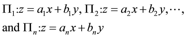 (1)
(1)
For convenient and united, we let x axis point to east, y axis to north, and z axis perpendicularly to up orientation.
Professor Shi originally used stereographic projection2 to transfer the planes onto the equatorial plane, and he applied topologic method to prove the existence of the orientation of landslip. Furthermore, Shi prevented landslip by piling to withstand landslip along the steepest decent orientation.
2. To Analyze the Landslip Orientation in the Case of Only One Landslip Plane
The basic supposition and deduction of compute formulas for the Case of Only One Landslip Plane are as follows.
Here suppose there is only one landslip plane P, whose equation is: , where
 . Its normal is
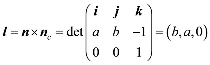
 . And the intersection line L of P and the contour plane z = constant C satisfies
 . The normal of
 ![]() is
is . Let the orientation of intersection L be
  then it holds
 (2)
(2)
Let ![]() denote the steepest ascent orientation, then it holds
denote the steepest ascent orientation, then it holds
 (3)
(3)
Let ,
,  ,
,  , then the steepest ascent orientation after normalization of horizontal project is denoted by
 , then
  is expressed as follows
 ,
,  ,
, (4)
(4)
where q denotes the horizontal angle in the xy plane during the steepest ascent, r the ascent gradient. From (a,b)one may compute . For the signs of
 , we have the following eight cases:
 (5)
(5)
If signs are , then
 , in the fourth quadrant. Let angle q denote the steepest ascent orientation. The steepest decent angle is
 , satisfies
 . The following open interval
 (6)
(6)
denotes the angle interval on horizontal plane, in which does not allow slip, called un-allowed interval. However the open interval
 (7)
(7)
denotes the angle interval on horizontal plane, in which allows slip, called allowed interval.
We explain basic properties for the case of Only One Landslip Plane.
Because the normal of the decent slip plane is , and the steepest ascent orientation is
 , the horizontal projects of
 ![]() and
and ![]() are equal to each other, i.e. equal to
are equal to each other, i.e. equal to . The orientation of intersectional line of the contour plane z = C and P is
 , whose horizontal project orientation is (b, -a), which is perpendicular to horizontal project of
![]() .
.
From (a,b) one obtains . We have supposed that q is an angle in {Oxy} horizontal plane for the steepest ascent case. If the signs of (a,b) are (+,+), then
 , in the first quadrant; if the signs of (a,b) are (-,-),
  , in the third quadrant. If the signs of (a,b) are (-,+), then
 , in the second quadrant. If the signs of (a,b) are (+,-), then
 , in the fourth quadrant.
The steepest decent angle is . In the horizontal plane the un-allowed open interval is
 . The allowed interval is
  . The intersectional line L of them is their boundary line.
Because the line L is horizontal, the weight is not able to move the isolated rock. However, if there is wind force, water force or earth force to move it, possibly it is able to produce horizontal movement. So the line L is critical line.
We have known that the normal of the slip plane P is , whose horizontal project is (a,b). The horizontal project orientation of intersectional line L is (b,-a), which is the critical orientation between
 ![]() and
and . The horizontal project of P is resolved to be
 .
.
However, the slip orientation  after normalization of horizontal project had not been mentioned in Shi’s paper [1].
The first case of plane division is as follows. When  and
and , q is in the first quadrant of xy plane, the decent orientation from north-east points to southwest. The support must from south-west points to northeast. If a denotes the angle of gradient, then we have
 , and
, and . (8)
. (8)
where  denotes the falling gradient of up support, a denotes the angle of altitude.
The included angle between plane P and horizontal plane  is equal to a. The intersection line between plane P and horizontal
  is
is .
.
Especially, when , the steepest ascent angle
 , the steepest decent angle
  , and
, and , the angle of gradient
 . The allowed angle interval is
 . And the angle interval
  is un-allowed to slip.
Now , the slip orientation points from northeast to south-west. In the practice, at the risk area, the support orientation should point from south-west to north-east according to the horizontal angle q, and to the angle of gradient a by piling to withstand landslip.
3. To Analyze the Other Seven Cases for the Plane Division in the Case of Only One Landslip Plane
The second case of plane division is as follows. When
 and
and ,
,  ,
,  , the slip orientation points from north to south. The support orientation should point from south to north. If a denotes the angle of gradient, then
 , and
, and . r is ascent gradient, a is ascent angle. The un-allowed angle interval is
 (9)
(9)
The allowed angle interval is
 (10)
(10)
The third case of plane division is as follows. When
 and
and ,
,  , in the second quadrant:
 , the slip orientation is from north-west to south-east. The support orientation is from south-east to north-west. If a denotes the angle of gradient, then
 , and
, and , where r is the gradient of ascent support, a is ascent angle.
The fourth case of plane division is as follows. When  and
and ,
,  , at -x axis;
 . The slip orientation is from west to east. The support orientation is from east to west. If a denotes the angle of gradient, then
 , and
, and , where r is ascent support gradient, a is ascent angle. The un-allowed interval is
 ; the allowed interval is
 .
.
The fifth case of plane division is as follows. When
 and
and ,
,  , in the third quadrant;
 , the slip orientation is from south-west to north-east. The support orientation should be from north-east to south-west. If a denotes the angle of gradient, then
 , and
, and , where r is ascent support gradient, a is ascent angle.
The sixth case of plane division is as follows. When
 and
and ,
,  , at -y axis;
 . The slip orientation is from south to north. The support orientation should be from north to south. If a denotes the angle of gradient, then
 , and
, and , where r is ascent support gradient, a is ascent angle. The un-allowed interval is
 ; the allowed interval is
 .
.
The seventh case of plane division is as follows. When
 and
and ,
,  , it is in the fourth quadrant, and the slip orientation is from south-east to north-west. The support orientation should be from north-west to south-east. If a denotes the angle of gradient, then
 , and
, and , where r is ascent support gradient, a is ascent angle.
The eighth case of plane division is as follows. When  and
and ,
,  , at +x axis, and
 . The slip orientation is from east to west. The support orientation should be from west to east. If a denotes the angle of gradient, then
 , and
, and , r denotes the ascent gradient of supporting, a is the angle of ascent supporting. The un-allowed interval is
 ; the allowed interval is
 .
.
4. The Case of Just Having Two Slip Planes
Now we suppose that  and
and  are two possible slip planes. If
  and
and  are parallel each other, and because the two planes have a common point: (0,0,0), they must be coincident, and turn to be the case of only one slip plane, as stated in the former section. Therefore we only discuss the case of that the two slip planes
  and
and  have an intersectional line. Suppose the equations of the two slip planes are as follows;
Suppose ,
, . The two planes have a common point: (0,0,0). Because we have supposed that
  and
and  have an intersectional line
 , then
  , and
, and  are not able to hold simultaneously. Because of the normal of
  is
is , and the normal of
  is
is . It follows that the orientation
  of
of  is denoted by3
 (11)
(11)
Let , after normalized horizontal project we have
 (12)
(12)
where
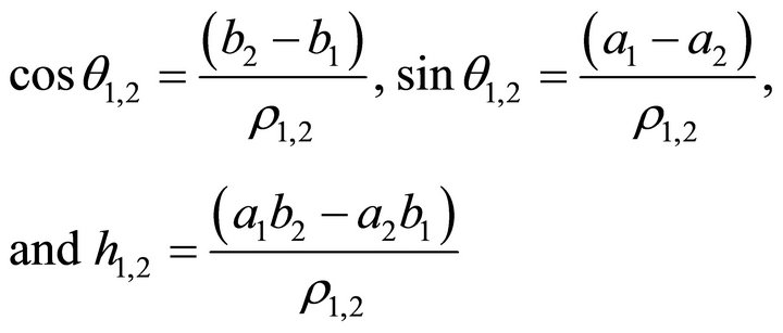 (13)
(13)
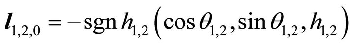
Let  denote the slip orientation under normalizetion horizontal project, then it holds the following formula
 (14)
(14)
Or in detail, when , it holds
 , (15)
while the slip horizontal angle is .
.
When , it holds
 , (16)
while it is not able to slip, called critical case.
When , it holds
 , (17)
while the slip horizontal angle is 
And the absolute value  denotes the decent gradient of intersection line
 . Besides if
  denotes the ascent angle for slip, then it holds
 ,
, (18)
(18)
5. Example for Just Two Slip Planes
Suppose  ,
, . For
. For
 .
. , The un-allowed interval is
 . And
. And , the ascent angle
 ,
,  is in the first quadrant in xy horizontal plane. The slip orientation is from north-east to south-west.
  is the steepest decent horizontal angle. The support orientation should be from south-west to north-east. The allowed interval is
 .
.
For . The signs are (-,+),
  ,
,  is in the second quadrant,
  ,
,  ,
,  , the slip orientation is from north-west to south-east. The support orientation is from north-west to south-east.
 . The un-allowed interval is
 ; the allowed interval is
 . The ascent angle
 .
.
The intersection of two allowed interval is as follows
 (19)
(19)
We have supposed that the intersectional line of  and
and  is
is , where
 ,
,  , it follows
 (20)
(20)
 (21)
(21)
 (22)
(22)
 (23)
(23)
 ;
; . (24)
And the decent gradient
 (25)
(25)
Refer to Equation (15), because , it holds:
 (26)
(26)
while the steepest slip horizontal angle is

Very fortunately, here the slip orientation of  is:
is: , which coincides with
  when
when , by using the formula in Equation (4) according to condition
 . Note that here
  is namely the plane
  when
when . The steepest decent angle is
 and
and , the ascent angle is
  . The allowed interval is
 . And the un-allowed interval is
 .
.  .
.
Very fortunately, here we have . In dealing with the landslip of an isolated rock in a tunnel, we should note not only the caving in along the slip orientation
  of the intersectional line
  of
of  and
and ; but also note the landslip along the steepest decent orientation
  of the plane
 . Therefore, the support area should be some what wider, while we should decide according to practical survey.
Note the following data for comparing:
 ;
; ;
;
 ;
; ;
;
 ;
; ;
;
 ;
; ;
;
To sum up, the damage orientations are three:
The slip orientation along the intersectional line 
 (27)
(27)
The steepest horizontal normalized slip orientation along P1:
 (28)
(28)
The steepest horizontal normalized slip orientation along P2;
 (29)
(29)
Fortunately, it holds here: . If having not done through repeated computations, only by intuition, it is difficult to see the result. In the paper [1] of Professor Shi Gen Hua, he claimed that the slip orientation
  of the intersectional line of the most damage one, the author also had the view. However the slip orientations
  and
and  had not be mentioned, which should be noted also.
According to the data of the problem, the most damage orientations are three: 1) The slip orientation  along the intersectional line
 ; 2) The steepest slip orientation
  along
along ; and 3) The steepest slip orientation
  along
along . Because the existence of
  forms a bound for the orientation
 ; but the existence of
  does not form a bound for the orientation
 . That needs a detail analysis for three orientations, please refer to the following minimal analysis.
Because the section appears fortunate case: , we must note special cases which appear occasionally like this kind.
Checking computations: Substituting  into
into  we get:
 . Substituting
  into
into  we get:
 . It is certainly the intersection of
  and
and .
.
The following is to find Allowed Slip Pyramid. Refer to Figure 1, the slip horizontal angle is ÐPOR. The allowed slip three edge pyramid formed by two planes  and
and  is as follows: The first edge is OP. The first boundary surface is
 . The second edge is
  which is under the ray q1, 2T. The second boundary surface is
 . The third edge is OR. The third boundary surface is the horizontal plane from OR to OP along clockwise.
The following is Minimal Analysis.
The horizontal project figure of  and
and .The allowed interval is
 .
.
Fortunately it holds which is the first minimal angle. However
 , which falls in the fourth quadrant and beyond the scope of ÐPO - q1, 2T, we do not take it. Therefore, in the section, the steepest slip horizontal angle is namely
 . The ascent angle is
 .
.
6. Example for Just Three Slip Planes
Suppose the first landslip plane  is:
is:  . Through computation, the normal of
  is:
is: ,
,
 ,
, .
.

Figure 1. The horizontal project figure for  and
and .
.
![]() ,
, .
.
 ;
;
the un-allowed interval is
 ;
;
and the allowed interval is
 .
.
Suppose the second landslip plane  is:
is: ; through computation we get: the normal of
  is:
is:
 ,
,
 ,
,
 .
.
![]() ,
,
 .
.
 ;
;
The un-allowed interval is
 ;
;
and the allowed interval is
 .
.
It follows that the orientation  of intersectional line
  is denoted by
 (30)
(30)
Let , and let
  denote horizontal normalized decent slip orientation, and
  the decent slip angle in the horizontal project plane,
  ,
,  , and
, and ; And the horizontal signs of
  is (0,-), then
  is on -y axisit holds
 , and
, and
 ,
, (31)
(31)
Because of it holds ; the decent slip orientation
  of
of  is a horizontal project normalized orientation. The angle
 (32)
(32)
On one hand, we must note the first paragraph in Section 6, the steepest decent slip orientation of  is
is
 (33)
(33)
The allowed interval is
 (34)
(34)
On the other hand, through computation we get: the steepest decent slip orientation of P10 is
 (35)
(35)
The allowed interval is
 (36)
(36)
Because of the intersection of  and
and  is
is
 (37)
(37)
This is the allowed decent slip interval.
Refer to Equation (37), it holds the inequalities
 (38)
(38)
It namely holds the membership
 (39)
(39)
And note that  denotes the ascent angle of the slip, it follows
 (40)
(40)
Suppose the third landslip plane  is:
is: 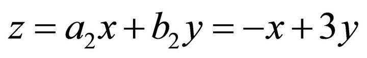 . Through computation we get: the normal of
  is
is ,
,
 ,
,
 .
.
![]() ,
, .
.
 ;
;
The un-allowed interval is
 ;
;
and the allowed interval is
 .
.
It follows that the orientation  of intersectional line
 ![]() is denoted by
is denoted by
 (41)
(41)
Let , and let
  denote the horizontal normalized decent slip orientation, and
  the slip angle in horizontal plane,
 ,
,  , and
, and ; And
; And ,
,  and the horizontal signs of
  are (-,-), then
  is in the third quadrant, it holds
 , which is between (
 ;
;  ). We have the following formulae

 (42)
(42)
Because it holds ; the decent slip orientation
  of
of ![]() is horizontal project normalization. The angle
is horizontal project normalization. The angle
 (43)
(43)
On one hand, through computation we get: the steepest decent slip orientation along  is
is
 (44)
(44)
The allowed interval is
 (45)
(45)
On the other hand, through computation we get:, the steepest decent slip orientation along  is
is
 (46)
(46)
The allowed interval is
 (47)
(47)
The intersection of  and
and  is
is
 (48)
(48)
This is the allowed interval of the slip.
Refer to Equation (43), it holds the inequalities
 (49)
(49)
It namely holds the membership
 (50)
(50)
And note that ![]() denotes the ascent angle of the slip, it holds
denotes the ascent angle of the slip, it holds
 (51)
(51)
 (52)
(52)
We have supposed that the intersectional line of  and
and  is
is , where
 ,
,  , it follows
 (53)
(53)
 (54)
(54)
 (55)
(55)
 (56)
(56)
 ;
; (57)
(57)
And the decent slip gradient is
 (58)
(58)
Refer to Equation (15), because of , it holds
 (59)
(59)
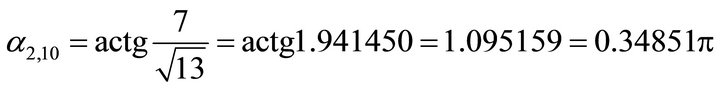
The steepest decent slip horizontal angle is
 .
.
Fortunately, here the decent slip orientation of  is
is , which is coincide with
  in section 2, above Equation (8). Note that here
  is namely the plane
  in the example in section 2, when
 . The steepest decent angle is
 , and
, and , the ascent angle
 .
.
The allowed interval is
 (60)
(60)
The un-allowed interval is
 (61)
(61)
 (62)
(62)
For three planes ,
,  and
and , the allowed interval is
 (63)
(63)
Therefore it holds the memberships
 (64)
(64)
 (65)
(65)
 (66)
(66)
Correspondingly, the ascent angles are
 (67)
(67)
 (68)
(68)
 (69)
(69)
And it holds the inequalities
 (70)
(70)
 (71)
(71)
Along counter clockwise, from  to
to  to
to , now
, now ![]() is the steepest decent gradient. How to analyze? At first we list the main data for planes as follows
is the steepest decent gradient. How to analyze? At first we list the main data for planes as follows
 (72)
(72)
 (73)
(73)
 (74)
(74)
Afterwards, we list the main data for intersectional lines as follows
 (75)
(75)
 (76)
(76)
 (77)
(77)
Now we draw the orientation figure of horizontal project as follows We give explanations for the Figure 2. Let the coordinates {Oxy} denote the horizontal project plane The straight angle under the line D2T-O-P is denoted by .
.
The straight angle on the left of the line D10T-O-P is denoted by .
.
The straight angle on the left of the line D1T-O-R is denoted by .
.
The angle of ray q1, 10T is denoted by
 .
.
The angle of ray q2, 10T is denoted by
 .
.
The angle of ray q1, 2T is denoted by
 .
.
The angle ÐPOQ denotes the allowed interval

Pyramid Allowed to Decent Slip
We start from OP, and let OP be the first edge. According to counter clockwise, the first boundary surface of pyramid is . Through computation we have
 ,
,  , and
, and .
.
Refer to the Figure 2, according to counter clockwise, the second edge of the pyramid is the edge  which is under the ray q1, 2T. Through computation, according to counter clockwise, the second boundary surface of the pyramid is
 .
. ,
,  ,
, .
.
Refer to the Figure 2, according to counter clockwise, the third edge of the pyramid is the edge ![]() which is under the ray q2, 10T. Through computation, according to counter clockwise the third boundary surface is still
which is under the ray q2, 10T. Through computation, according to counter clockwise the third boundary surface is still . The third edge under q2,10T is covered by
 .
. ,
,  ,
, .
.
Refer to the Figure 2, according to counter clockwise, the fourth edge of the pyramid is the edge  which is under the ray q1, 10T. Through computation, according to counter clockwise, the fourth boundary surface of the pyramid is
  or
or .
. ,
,  ,
, .
.
Refer to the Figure 2, according to counter clockwise, the fifth edge of the pyramid is OQ. Through computation, according to counter clockwise, the fourth boundary surface is defined by .
. ,
,  ,
, .
.
Refer to the Figure 2, the fifth boundary surface of the pyramid is defined by the horizontal plane which is from OQ to OP according to clockwise.
To sum up, the allowed decent slip pyramid degenerates to be a four edge pyramid, whose boundary surface begin with the edge OP, through  to the edge under q1, 2T, and through
  to the edge
  under q1, 10T, and through
  arrived OQ, and according to clockwise, through horizontal plane to the edge OP.
Through minimal computation, the final conclusion is as follows: in the four edge pyramid of the section,
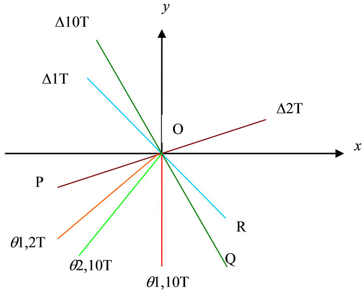
Figure 2. The orientation figure of horizontal project.
 is the steepest decent slip orientation.
We should firstly reinforce along the orientation, i.e. from south-west to north-east, with ascent angle , to reinforce.
Minimal value, i.e. the steepest decent slip orientation is along the edge  which is under the ray q1, 2T
7. Discussions for the Case of m Slip Planes
According to Section 1, let  and
and  be m possible slip planes, where m is a natural number. Their equations are expressed by
  and
and  . For convenient and unification, the x axis points to east, the y axis points to north, and the z axis points to up.
Suppose 
Among them, we choose an element , whose equation is
 . Its normal is
 . And the intersectional line
  of the contour plane
 ![]() and
and  satisfies
 . The normal of
 ![]() is
is . Let
. Let  be the orientation of intersectional line
 , it follows
 (78)
(78)
Let ![]() denote the steepest ascent orientation, it follows
denote the steepest ascent orientation, it follows
 (79)
(79)
Let  denote the horizontal project of the steepest ascent orientation
![]() , which is also the horizontal project of normal
, which is also the horizontal project of normal , i.e. it holds
 (80)
(80)
This is a deputation of plane .
.
Let![]() ,
, 
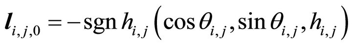
 , the horizontal project decent slip orientation is denoted by
 , then
  is able to be expressed by
 (81)
(81)
Let  denote the horizontal normalized project of the steepest ascent orientation, then it follows
 (82)
(82)
The intersectional line of two planes  and
and  is
is , whose orientation
  is expressed as follows
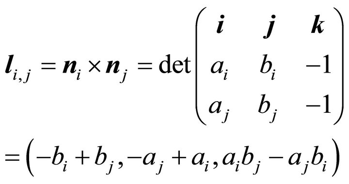 (83)
(83)
Let , after horizontal project normalizing one obtains
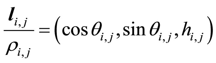 (84)
(84)
where
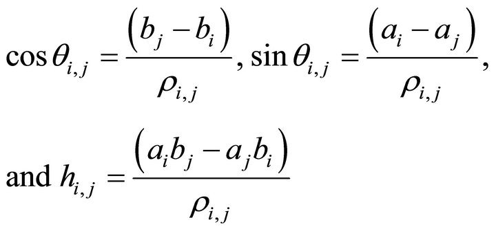 (85)
(85)
Let  denote the decent slip orientation of horizontal project normalization, then it holds
 (86)
(86)
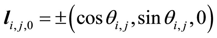
Or in detail, when , it holds:
 , (87)
while the decent slip horizontal angle is 
When , it holds
 , (88)
while don’t produce slip, it may produce horizontal movement, it is critical line.
When , it holds
 (89)
(89)
while the decent slip horizontal angle is 
And the absolute value  denotes the decent slip gradient of the intersectional line
 . And if
  denotes the ascent angle of the decent slip, then it holds
 ,
, (90)
(90)
The steepest decent slip horizontal angle is
 . The un-allowed horizontal angle open interval is
 . The allowed interval is
 . The horizontal intersectional line
  is their boundary line.
7.1. “Un-Allowed Straight Angle Law” about m Planes
Now we draw the figure of the un-allowed straight angle law about m planes as follows.
In the Figure 3, we draw the m steepest ascent angle  and
and  whose corresponding rays are denoted by
  and
and  and the corresponding m planes are
  and
and . Suppose they permute according to counter clockwise.
There is an angle between two adjacent rays. Suppose all the angles are less than p, i.e. less than a straight angle, then the un-allowed intervals  and
and  formed by m planes
  and
and  cover the whole circumference angle. Therefore, there is not any horizontal angle which is allowed decent slip. This may be simply called un-allowed straight angle law.
7.2. “Critical Straight Angle Law” about m Planes
Now we draw the figure of the critical straight angle law about m planes as follows.
In the Figure 4, we draw the m steepest ascent angles  and
and  whose corresponding rays are denoted by
  and
and  and the corresponding m planes are
  and
and . Suppose they permute according to counter clockwise.
There is an angle between two adjacent rays. Suppose among the angles there is an angle equal to p, i.e. equal to a straight angle. No harm of the generality, suppose the angle between qm and q1 is equal to p, then the critical line  between
  and
and  is namely the critical line among
  and
and .
.
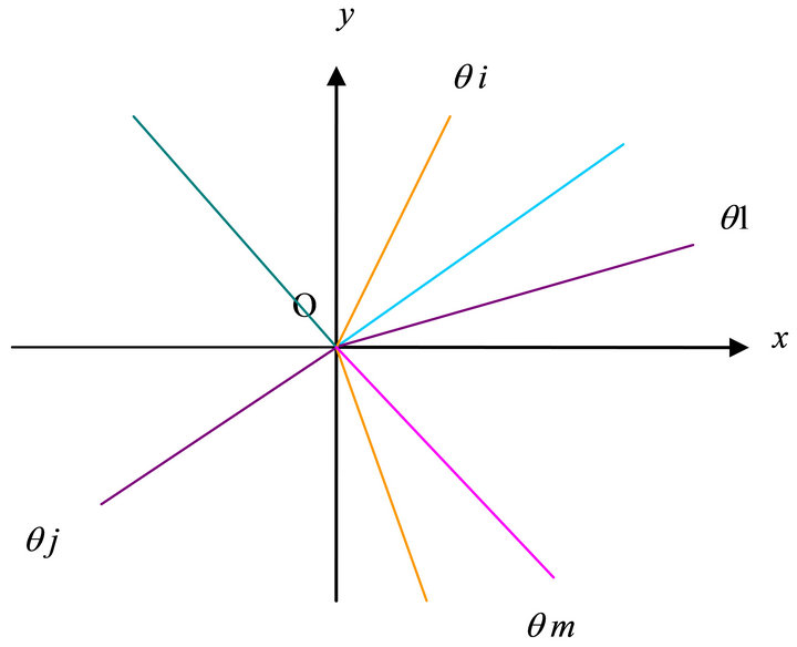
Figure 3. The figure of un-allowed straight angle law.

Figure 4. The figure for critical straight angle law.
This is called critical straight angle law. If there is wind force, water force or earth force to move it, possibly it is able to produce horizontal movement.
7.3. “Allowed Straight Angle Law” about m Planes
Now we draw the figure of the allowed straight angle law about m planes as follows.
In the Figure 5, we draw the m steepest ascent angle  and
and  whose corresponding rays are denoted by
  and
and  and the corresponding m planes are
  and
and . Suppose they permute according to counter clockwise.
There is an angle between two adjacent rays. No harm of generality, suppose along counter clockwise the angle ÐqmOq1 is more than p, i.e. more than a straight angle. The angle ÐqmOP is equal to a right angle, then the angle ÐPOQ which is more than zero, is the intersectional part of all allowed angles  and
and , and is called allowed interval D. Because of the existence of allowed interval D, which is called allowed straight angle law.
Let  denote the intersectional line of
  and
and  Generally let
  denote the intersectional line of planes
  and
and , then the set
  have
have
 elements. And there are m plane steepest decent slip angles
  and
and , which is denoted by the set
 .
.
Let the intersectional set  denote the set of all intersectional lines in the angle ÐPOQ. Let the intersectional set
  denote the set of all steepest decent slip angles in the angle ÐPOQ. Afterwards, we
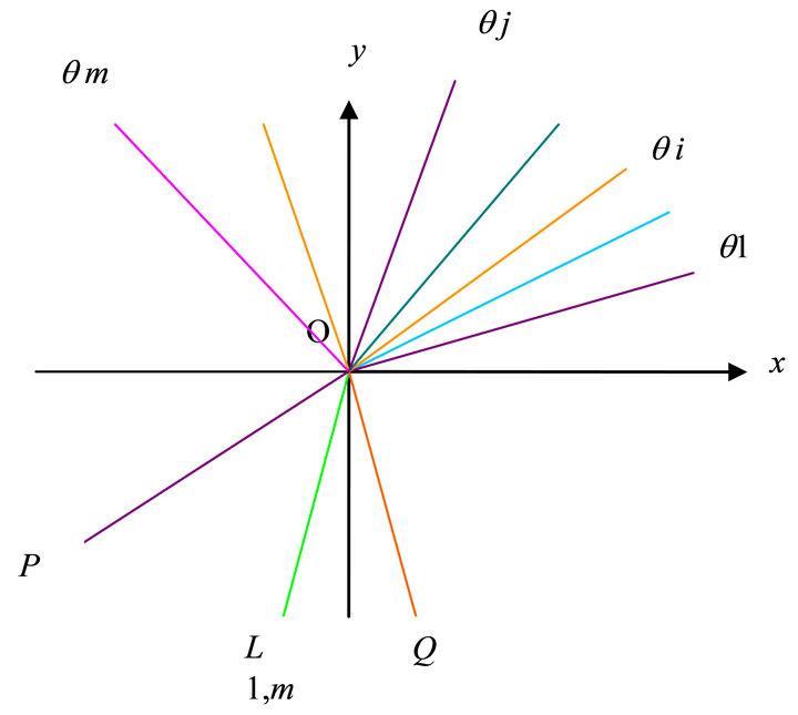
Figure 5. The figure of allowed straight angle law.
compare the z values along these orientations on unit sphere. How to analytically compare? Please refer to Section 6: the example for just have three decent slip planes, in which we should give up some planes and orientations. After sifting we need only analytically compare the values on the left orientations, in which the orientation of the minimal z value is just the steepest decent slip angle formed by m planes  and
and . This is the most important orientation which need reinforce.
8. Project Expression of Landslip Plane on Unit Sphere
If thinking of the theoretical beauty-ness, one should naturally use the unit spherical project
8.1. Inspiration from the Computation along One Orientation
Now let  to be an example, while the allowed interval is
 ,
,
 ,
, . The ascent angle
  .
. ,
,  .
.
The component , is the vertical component of the intersectional point of the ray formed by
  and on the lower semi unit sphere. Because of
 , the steepest ascent orientation is
 , and the steepest decent slip orientation is
  .
.
The equation of unit sphere is . Let
. Let ,
, . And let
 (91)
(91)
Now , it follows
 (92)
(92)
8.2. An Example of Practical Computation on the Project of Unit Sphere
We consider on plane z = 0 the following ellipse whose long radius is equal to 1, and short radius is equal to . The orientation of long radius is x, pointed to
 . The orientation of short radius is h, pointed to q.
The equation of the ellipse in the coordinates {xOh} is as follows
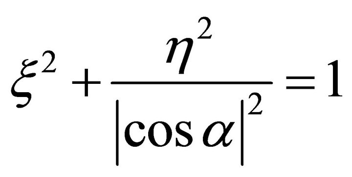 (93)
(93)
We plan to solve the equation of the ellipse in the coordinates {xOy}. In order to doing this, we should find the corresponding formula of the coordinate transformation. Therefore we should firstly draw the hint figure of coordinate transformation.
The hint Figure 6 for coordinate transformation is as follows.
In the figure y denotes the angle from Ox axis to Ox axis, whose measure is equal to the angle from  to Ox axis. In the problem, refer to the first and second paragraphs of article 8.1, because of
 , we have
 (94)
(94)
The deduction of the formula for coordinate transformation: let
 (95)
(95)
Because of
 (96)
(96)
It follows the formula
 (97)
(97)
Finally, we obtain
 (98)
(98)
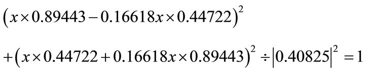
The above elliptic Equation (93) changes into
 (99)
(99)
For the decent slip plane P, the allowed interval is ,
,
 . Now we divide
  into equidistance
  components. In practice the n should be 2, 3, or 4. In the section being only a hint, so we take
 . Note
 . Similarly, we have the data as follows Let
 ,
,
 ,
,
 ,
,
 ,
,
 ,
,
 ,
,
 ,
,
 ,
,
 ,
,
 ,
,

In the plane  for the ray with orientation j, its orientation vector is
 , its normal is
 , and its equation is as follows
 (100)
(100)
Note ,
,  ,
,
 . And note
 ,
,
 . The equation of the ellipse is as follows
 (101)
(101)
 (102)
(102)

Figure 6. The hint figure for coordinate transformation formula.
The detail numerical computation is as follows :
For , its orientation vector is
  . Because its signs are (-,+), the solution (x,y) falls in the second quadrant. Then we use the normal equation:
  . Substituting into the ellipse in Equation (102) one obtains:
 ;
;
 .
.
When it holds: , from the normal equation one obtains:
 . Substituting into
 ;
;  ; one obtains
  , which does not fall in the second quadrant, so we give up it.
When it holds: , still from the normal equation one obtains:
 . Substituting it into
 ,
,  , one obtains:
  ;
; . It is just wanted, the computation is correct.
  , coinciding.
For , firstly we compute the orientation vector:
 . Because its signs are (-,+), the solution (x,y) falls into the second quadrant. Then we use the normal equation:
  ;
;  Substituting into the ellipse in Equation (102) one obtains:


By taking the negative, one obtains: ;
; .
. .
.
For , firstly, we compute the orientation vector:
 . Because its signs are (-,-), the solution falls in the third quadrant. Then by using the normal equation one obtains:
 ;
;  . Substituting into the ellipse in Equation (102), one obtains

By taking the negative, one obtains:
For , firstly, we compute the orientation vector:
 . Because its signs are (-,-), the solution (x,y) falls in the third quadrant. Then by using the normal equation one obtains:
 ;
;  . Substituting into the ellipse in Equation (102) one obtains


By taking the negative, one obtains:
For , firstly, we compute the orientation vector:
 . Because its signs are (-,-), the solution (x,y) falls in the third quadrant. Then by using the normal equation one obtains:
 ;
;  . Substituting into the ellipse in Equation (102) one obtains:

 .
.
By taking the negative one obtains:
For , firstly, we compute the orientation vector:
 . Because its signs are (-,-), the solution (x,y) falls in the third quadrant. Then by using the normal equation one obtains:
 ;
;  . Substituting into the ellipse in Equation (102) one obtains:

 .
.
By taking the negative, one obtains: ;
; .
.
 , that coincides with
 in the first paragraph in Article 8.1. Therefore the computation is correct.
For , firstly, we compute the orientation vector:
 . Because its signs are (-,-), the solution (x,y) falls in the third quadrant. Then by using the normal equation one obtains:
 ;
; . Substituting into the ellipse in Equation (102) one obtains:


By taking the negative, one obtains: ;
; .
. . It coincides with
  of
of . So the computation is reasonable.
For , firstly, we compute the orientation vector:
  Because the signs are (+,-), the solution (x,y) falls in the fourth quadrant. Then by using the normal equation one obtains:
 ;
;  . Substituting into the ellipse in Equation (102) one obtains:

 .
.
By taking the positive, one obtains: ;
; .
.  It coincides with
  of
of . Therefore, the computation is reasonable.
For , firstly, we compute the orientation vector:
 . Because the signs are (+,-), the solution (x,y) falls in the fourth quadrant. Then by using the normal equation one obtains:
 ;
;  . Substituting into the ellipse in Equation (102) one obtains:

 .
.
By taking the positive, one obtains: ;
; .
. . It coincides with
  of
of . Therefore, the computation is reasonable.
For , firstly, we compute the orientation vector:
 . Because the signs are (+,-), the solution (x,y) falls in the fourth quadrant. Then by using the normal equation one obtains:
 ;
;  . Substituting into the ellipse in Equation (102) one obtains:

 .
.
By taking the positive, one obtains: ;
;
 .
. . It coincides with
  of
of . Therefore, the computation is reasonable.
For , firstly, we compute the orientation vector
 . Because the signs are (+,-), the solution (x,y) falls in the fourth quadrant. Then by using the normal equation one obtains:
 ;
;
 . Substituting into the ellipse in Equation (102) one obtains:

 .
.
By taking the positive, one obtains: ;
; .
. . It coincides with
  of
of . Therefore, the computation is reasonable.
8.3. General Description for the Project Computation on Unit Sphere
The equation of decent slip plane P is z=ax+by, whose normal orientation is: . From (a,b), one obtains
 . Suppose q denotes the steepest ascent angle in the horizontal plane {Oxy}, then by using (a,b) one obtains
 . It follows the steepest decent angle
 , the allowed interval is
 . The equation of unit sphere is
 (103)
(103)
Let ,
,  , and
, and , then after horizontal project normalized the steepest ascent orientation is denoted by
 , which may be expressed by
 ,
,  , and
, and . The ascent angle is
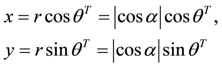
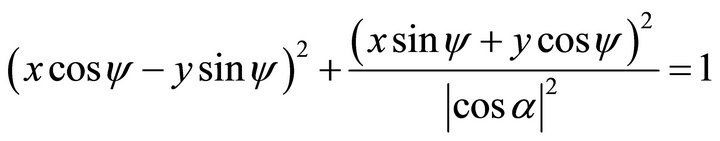
In the plane , we consider the following ellipse, whose long radius is equal to 1, and short radius equal to |cosa|. The orientation of long radius is x, whose orientation denotes to the angle
 . The orientation of short radius is h, whose orientation points to q. In the coordinates {xOh}, the equation of the ellipse is as follows
 (104)
(104)
We want to find the equation of the ellipse in the coordinates {xOy}. Refer to the Figure 6, in which y denotes the angle from Ox axis to Ox axis. The coordinate transformational formula is ; and
; and . Substituting into Equation (104), one obtains
 (105)
(105)
Let ,
,  , then
 , the allowed interval is
 . Now we divide
  into equidistance
  sub-intervals; i.e. we take a set
![]() , where
, where . Let
. Let , and let
 ,
,  ,
,  ,
, .
.
The computational process: for given , we firstly compute the orientation vector
 . According to its signs, we define what quadrant does the solution
  fall in, or what axis it falls on. Then by using the normal equation:
 ; we determine
 . Substituting into the ellipse in Equation (105), one obtains
 (106)
(106)
From the above formula and refer to quadrant what the solution  falls in, or what axis the solution falls on, then we solve the value of
 . Then we compute:
 . And by using the formula
![]() (107)
(107)
we compute the value![]() . The three dimensional coordinates
. The three dimensional coordinates  is namely the intersectional point of the plane P and the unit sphere along the orientation angle
 .
.
For the set![]() , after finding the corresponding three dimensional points, one obtains a downward semi circular plane. The solid angle between it and the horizontal plane is namely the domain of allowed decent orientation.
, after finding the corresponding three dimensional points, one obtains a downward semi circular plane. The solid angle between it and the horizontal plane is namely the domain of allowed decent orientation.
For the discussion of m planes, refer to Section 7, here we don’t repeat it.
8.4. Complements for Vertical Plane
In view of theory, it is possible for the existing of a decent slip plane  which is perpendicular to the horizontal plane. Suppose the equation of
  is
is , where
 . Its normal has two possibilities:
 , and
, and , in which there is only one who points to the solid part of
 , denoted by:
 . Then it holds:
 . The equation of
  turns into:
 , i.e.
 .
.
From (a,b) it follows . Suppose q is the steepest ascent angle in horizontal plane {Oxy}, then from the signs of (a,b) we are able to determine
 . Then we solve the steepest decent angle
 , and the allowed interval
Let y denote the angle from Ox axis to Ox axis, whose value is equal to the angle from  to Ox axis. We have the following coordinate transformational formula
 (108)
(108)
In the coordinates {Oxhz}, the equation of unit sphere is as follows
 (109)
(109)
whose project G on the plane  is as follows:
 (110)
(110)
Transforming into the coordinates {Oxyz}, the equations of G is as follows
 (111)
(111)
and
 (112)
(112)
When , one solves
 (113)
(113)
Substituting into Equation (111) one obtains
 (114)
(114)
 (115)
(115)
This is an ellipse whose long radius is equal to 1 and on z axis, and whose short radius is equal to |cosy| and on x axis. This is a formula expression in coordinate {Oxz} of G which is the project of the great circle of unit sphere on the plane . We solve
 (116)
(116)
When ,
,  ,
, . It coincides. When
 ,
,  ,
,  , this is the steepest decent slip orientation. It coincides.
When , one solves
 (117)
(117)
Substituting into Equation (111) one obtains
 (118)
(118)
 (119)
(119)
where is an ellipse with its long radius equal to 1 and on z axis, and its short radius equal to  and on y axis. This is a formula expression in coordinate {Oyz} of G which is the project of the great circle of unit sphere on the plane h = 0. We solve
 (120)
(120)
When ,
,  ,
, . This coincides. When
 ,
,  ,
, . This is the steepest decent slip orientation. It also coincides.
From formulas Equation (113), Equation (115) and satisfying the condition Equation (116), for every given x value, we may compute z value for y = 0. Therefore, we can draw the locus of G.
In order to solve the solid angle between F and G, where F is the horizontal semi circle of unit circle  along the orientation
 , let
, let ,
,
 ,
,  , then we take a set
![]() , where
, where . Let
. Let , and let
 ,
,  ,
,  ,
, . According to the coordinates (x,y), one may draw the figure of F.
Because the data of the figure of vertical plane has solved, it follows that the mathematical method for spherical project of landslip plane is also obtained. For the detail of figure, please refer to three dimension software. The author must do an optimal stopping now.
REFERENCES
- S. G. Hua, “Stereographic Projection of Rock Stable Analysis,” Scientia Sinica, Vol. 3, No. 5, 1977, pp. 260-272. (in Chinese)
- I. Shokichi, “Encyclopedic Dictionary of Mathematics,” Iwanami Shoten, Tokyo, 1954, p. 459.
- W. G. Lei and T. Chou, “A Short Course of Analytical Geometry,” 2nd Edition, High Education Press, Beijing, 2007. (in Chinese)
NOTES
1Refer to [3], pp. 10-11, general equation of a plane.
2For stereographic projection, please refer to p. 459 in EDM [2].
3Refer to book [3], pp. 44-45, in the item “vector product of vectors”.