Energy and Power Engineering
Vol.12 No.02(2020), Article ID:98530,13 pages
10.4236/epe.2020.122007
Heat Transfer and Energy Utilization of Waste Heat Recovery Device with Different Internal Component
Enmin Tang1, Jing Ding2, Jianfeng Lu2*
1School of Intelligent Systems Engineering, Sun Yat-sen University, Guangzhou, China
2School of Materials and Engineering, Sun Yat-sen University, Guangzhou, China

Copyright © 2020 by author(s) and Scientific Research Publishing Inc.
This work is licensed under the Creative Commons Attribution International License (CC BY 4.0).
http://creativecommons.org/licenses/by/4.0/


Received: January 3, 2020; Accepted: February 24, 2020; Published: February 27, 2020
ABSTRACT
Steel industry is high energy-consuming industry, and its waste heat recovery is critically important for energy utilization. In this study, pipeline bundle is used to enhance heat transfer in waste heat recovery device, and associated gas-solid heat transfer and energy utilization performance with different pipeline arrangement, pipe diameter and shape of internal component are further analyzed. The temperatures of gas and particle in device with pipeline bundle periodically fluctuate in horizontal direction, and those in staggered system distribute more uniformly than those in paralleled system. Compared with paralleled device, exergy and waste heat utilization efficiency of staggered device have been improved, and they are both higher than those without pipeline. As pipe diameter increases, exergy and waste heat utilization efficiency first increases and then decreases, and they reach the maxima with optimal pipe diameter. As the width of internal component keeps constant, influence of its shape on heat transfer is very little.
Keywords:
Waste Heat Recovery Device, Porous Media, Local Thermal Non-Equilibrium, Gas Solid Heat Transfer

1. Introduction
The steel industry has always been the top priority of national industry, and energy consumption of blast furnace steelmaking can reach 40% of total energy consumption in steel industry, 10% - 15% of total energy consumption in the country, belonging to high energy-consuming industry [1].
Shigaki et al. [2] rolled slag into a sheet and passed it into a packed bed for waste heat recovery, and they found that sensible heat recovery efficiency can be up to 43%. Hadley et al. [3] established a countercurrent packed bed heat transfer model, and obtained ratio of mass flow rate of gas and particles at lowest particle outlet temperature and highest gas outlet temperature through experimental research. South Korea’s Posco proposed a waste heat recovery solution that pelletizes the slag and flows into heat exchanger through a slope, and waste heat utilization efficiency can be as high as 50% [4]. Liu et al. [5] [6] [7] built self-flow bed heat exchange device for indirect heat exchange between particles and water in a pipeline, and they found that smaller slag particle size and larger slag particle velocity had higher overall heat transfer coefficient and the waste heat recovery efficiency. Zhao et al. [8] compared sensible heat recovery efficiency of ring-type and vertical type waste heat recovery devices through exergy analysis method, and found that efficiency of vertical type of waste heat recovery device was significantly higher than ring type one. Dong et al. [9] studied effects of operating parameters and structural parameters on gas flow in vertical waste heat recovery device, and effects of parameters such as particle diameter on waste heat recovery efficiency and exergy were analyzed [10] [11] [12]. Chen et al. [13] founded that device height and gas-solid ratio in vertical device had a large effect on exergy, and its required air volume was much smaller than ring one. Fu et al. [14] performed numerical analysis on vertical device to obtain optimal operating conditions. In addition, Australian CSIRO [15] [16] used semi-industrialized equipment in slag waste heat recovery, and waste heat recovery rate can reach 50%. Rouaban et al. [17] studied recycling and utilization of slag in road construction in Algeria. Al-Baijat et al. [18] found that using slag can improve concrete properties.
At present, there are few studies on the influence of waste heat recovery device with different internal components on gas-solid heat transfer and waste heat utilization. In this paper, gas-solid heat transfer and waste heat utilization efficiency in waste heat recovery device with different pipeline arrangements, pipe diameter and shape of internal component is simulated. In addition, effects of inlet gas velocity, inlet gas temperature, particle diameter and particle porosity are further considered.
2. Physical Model and Validation
2.1. Physical Model
The schematic diagram of waste heat recovery device is shown in Figure 1, and different pipe arrangements and shape of internal component are studied. The 2D model of waste heat recovery devices size is 2.2 × 3 m. High temperature particle and cold gas exist countercurrent flow heat transfer. The gas-solid heat transfer is complex, so following assumptions are made:
1) The simulation process is steady state, and operating parameters are constant.
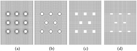
Figure 1. Waste heat recovery device with different internal components. (a) Paralleled; (b) Staggered; (c) Quadrate; (d) Rectangle.
2) Porous media model is used for simulation. Porous media is homogenous material, and the temperature of the particles is uniform.
3) Considering convection and heat conduction between particle and fluid in porous media, regardless of influence of radiation and heat loss.
2.2. Governing Equation
Continuous equation:
(1)
Momentum equation:
(2)
where ρ is density, kg/m3; ui is flow velocity in i direction, m/s; P is pressure, Pa; g is acceleration of gravity, m/s2; Si is momentum source term; μ is viscosity, Pa·s.
When the porous medium model is used, the momentum source term is added to the equation to add the effect of porous medium on the fluid.
(3)
The viscous resistance coefficient and the inertia resistance coefficient can be expressed as [19] :
(4)
(5)
where ε is particle porosity; ds is particle diameter, m.
The local thermal non-equilibrium:
(6)
(7)
where T is temperature, K; λ is thermal conductivity, W/(m·K); h and he are heat transfer coefficient and effective heat transfer coefficient, W/(m2·K); cp is specific heat of particle, J/(kg·K); subscripts “s” and “g” represent particle and gas respectively.
According to the Achenbach, the specific surface area can be expressed as [20] :
(8)
Also consider the effect of the internal heat transfer of the particles on the overall heat transfer coefficient, the heat transfer coefficient is corrected. The effective heat transfer coefficient according to Jefferson can be expressed as [21] :
(9)
where Nu is used the association proposed by Ranz [22] :
(10)
The quantity of waste heat utilization is expressed as:
(11)
The exergy of gas (Ex) is expressed as:
(12)
The waste heat utilization efficiency (η) is expressed as:
(13)
where β is heat capacity ratio; T0 is ambient temperature, K; q is air mass flow rate, kg·s−1; subscripts “in” and “out” represent the inlet and outlet.
The equations are solved by Fluent. The local thermal non-equilibrium energy equations are applied by UDF and UDS. The material density, specific heat and other parameters are set by UDF and Fluent database, grid is divided by ICEM, and pressure velocity coupling is solved by SIMPLE algorithm. The turbulence model adopts k-ε model, and residual convergence criterion is less than 10−6.
The gas density is 1.225 kg/m3, air specific heat can be calculated by Equation (14); particle gas density is 2900 kg/m3, particle specific heat can be calculated by Equation (15).
(14)
(15)
2.3. Model Validation
This paper uses experiment of Feng [10] to verify the model. This paper studies the heat recovery at steady state, and experimental results and simulation data are compared as Table 1. Experimental results have good agreement with simulation data with maximum deviation of 3.74%.
3. Results and Discussions
3.1. Basic Heat and Mass Transfer Performance
Figure 2 presents temperature field in heat recovery device with different pipe arrangement. When there are pipelines, the flow changes, and then gas-solid heat transfer will be significantly enhanced. Compared with paralleled pipeline arrangement, the staggered arrangement can reduce the temperature heterogeneity, and heat transfer is expected to be enhanced better.
Temperature and velocity evolution in horizontal direction of paralleled device are shown in Figure 3. Due to the influence of pipeline distribution, gas velocity and temperature in horizontal direction periodically change. Below the pipeline, the velocity and temperature are lower, and the temperature difference between gas and particle are also lower.
Temperature and velocity evolution in horizontal directions of staggered device are shown in Figure 4. The fluctuating amplitudes of gas velocity and temperature in staggered device are smaller than those of the paralleled one, and the period is decreased by half.
3.2. Effect of Inlet Condition
Figure 5 shows outlet gas and particle temperatures with different inlet gas

Table 1. Simulation and experimental comparison [10].

Figure 2. Temperature field in heat recovery device with different pipe arrangement. (a) Air temperature; (b) Particle temperature; (c) Air temperature; (d) Particle temperature.

Figure 3. Temperature and velocity changes in horizontal directions of paralleled device (y = 1.25 m).
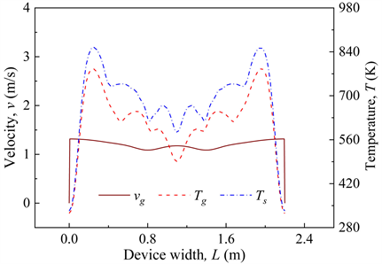
Figure 4. Temperature and velocity changes in horizontal directions of staggered device (y = 1.25 m).

Figure 5. Outlet gas and particle temperatures with different inlet gas velocity.
velocity in different devices. As inlet gas velocity increases, outlet gas temperature and outlet particle temperature drops. The increase of inlet gas velocity results in an increase in heat transfer coefficient, which leads to a decrease in outlet particle temperature. At the same time, larger mass flow rate of gas requires more energy, resulting in a decrease in outlet gas temperature.
Figure 6 shows outlet gas and particle temperatures with different inlet gas temperatures. In general, outlet gas and particle temperatures have similar tendencies with different inlet gas temperatures. As inlet gas temperature is increased, inlet enthalpy of gas increases, and outlet temperatures of gas and particle almost linearly rise, and outlet particle temperature changes more quickly.
3.3. Effect of Particle Property
3.3.1. Particle Diameter
Figure 7 shows outlet gas and particle temperatures of the device with different particle diameters. As particle diameter is reduced, outlet gas temperature

Figure 6. Outlet gas and particle temperatures with different inlet gas temperatures.

Figure 7. Outlet gas and particle temperatures with different particle diameter.
increases and outlet particle temperature decreases, because the reduction of particle size will increase effective heat transfer coefficient between gas and particle.
Figure 8 presents exergy and waste heat utilization efficiency of the device with different particle diameter. As particle diameter decreases, exergy and waste heat utilization efficiency increase for sufficient gas-solid heat transfer.
3.3.2. Particle Porosity
Figure 9 shows outlet gas and particle temperatures of the device with different particle porosity. Apparently, the increase in particle porosity reduces outlet gas temperature and outlet particle temperature. As particle porosity increases, particle density decreases, and the energy that particles can carry decreases, so outlet gas and particle temperatures decrease.
Figure 10 shows the effect of particle porosity on exergy and waste heat utilization efficiency for different internal components. As the porosity increases, the

Figure 8. Effects of particle diameter on exergy and waste heat utilization efficiency.

Figure 9. Outlet gas and particle temperatures with different particle porosity.

Figure 10. Exergy and waste heat utilization efficiency with different particle porosity.
exergy decreases, and the waste heat utilization efficiency increases. It is shown that although particle porosity decrease can increase the exergy, it will also reduce the waste heat utilization efficiency. It is necessary to choose a reasonable value to use.
3.4. Effect of Internal Component
3.4.1. Different Arrangement Effect
Form Figure 2 and Figure 5, outlet gas temperature in staggered pipeline system is higher than that in paralleled one, and that without pipeline is lowest. As a result, heat transfer with staggered pipeline is best, because its temperature distribution is more uniform. Figure 11 presents exergy and waste heat utilization efficiency in device with different pipe arrangement. Similar to heat transfer performance, the exergy and waste heat utilization efficiency of staggered pipeline system is higher than that in paralleled one, and that without pipeline is lowest.
3.4.2. Different Pipe Diameter
Figure 12 shows exergy and waste heat utilization efficiency in device with different pipe diameter, where vg,in = 1.2 m/s. As pipe diameter increases, exergy and waste heat utilization efficiency first increases and then decreases. As pipe diameter is 0.15 m, exergy and waste heat utilization efficiency reach the maxima of 4.26 GJ/h and 82.5%.
3.4.3. Different Shape of Internal Component
Figure 13 presents temperature fields in devices with different shape of internal component and identical width. As can be seen from Figure 13, the temperature fields are very similar with different shape of component.
Figure 14 presents outlet gas and particle temperatures of device with different shape of internal component. For different shape of internal component, the outlet gas and particles temperature changes very little, and exergy and waste
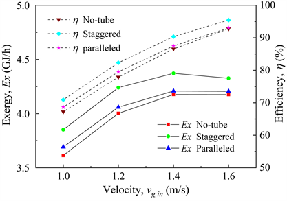
Figure 11. Exergy and waste heat utilization efficiency in device with different pipe arrangement.

Figure 12. Exergy and waste heat utilization efficiency in device with different pipe diameter (v = 1.2 m/s).
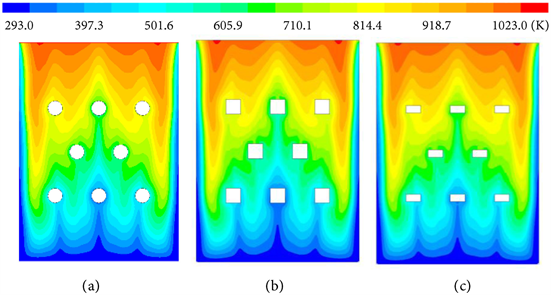
Figure 13. Temperature fields in device with different shapes of component. (a) Circle component; (b) Quadrate component; (c) Rectangle component.
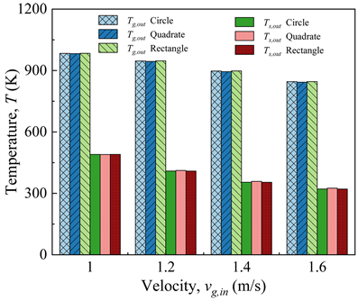
Figure 14. Outlet gas and particle temperatures of device with different shape of internal component.
heat utilization efficiency also keeps almost constant.
4. Conclusions
The heat transfer and energy utilization performance in waste heat recovery device with different pipeline arrangements, pipe diameter and shape of internal component is simulated and studied, and conclusions are as follows.
1) In waste heat recovery device with pipeline bundle, gas velocity and temperature in horizontal direction periodically change. Compared with paralleled arrangement, the system with staggered arrangement has more uniform temperature distribution and higher outlet gas temperature.
2) By using pipeline bundle, gas-solid heat transfer and energy utilization can be significantly enhanced. The exergy and waste heat utilization efficiency of staggered pipeline system is higher than that in paralleled one, and that without pipeline is lowest.
3) As pipe diameter increases, exergy and waste heat utilization efficiency first increases and then decreases, and they reach the maxima with optimal pipe diameter. The shape of internal component with identical width has little effect on exergy and waste heat utilization efficiency.
4) As inlet gas temperature or particle diameter increases, exergy and waste heat utilization efficiency decreases; as particle porosity increases, exergy decreases, and waste heat utilization efficiency increases; as inlet gas velocity increases, exergy increases first and then decreases, and waste heat utilization efficiency increases all the time.
Acknowledgements
This paper is supported by Natural Science Foundation of Guangdong Province (2017B030308004) and National Natural Science Foundation of China (U1601215, 51961165101).
Conflicts of Interest
The authors declare no conflicts of interest regarding the publication of this paper.
Cite this paper
Tang, E.M., Ding, J. and Lu, J.F. (2020) Heat Transfer and Energy Utilization of Waste Heat Recovery Device with Different Internal Component. Energy and Power Engineering, 12, 88-100. https://doi.org/10.4236/epe.2020.122007
References
- 1. Jiang, C. (2016) A Research and Simulation of Hybrid Waste Heat Recovery Device of Blast Furnace Slag. Master’s Thesis, University of Science and Technology Liaoning, Tianjin.
- 2. Shigaki, N., Tobo, H., Ozawa, S., Ta, Y. and Hagiwara, K. (2015) Heat Recovery Process from Packed Bed of Hot Slag Plates. ISIJ International, 55, 2258-2265. https://doi.org/10.2355/isijinternational.ISIJINT-2015-169
- 3. Hadley, T.D., Pan, Y., Lim, K.S. and Orellana, L. (2015) Engineering Design of Direct Contact Counter Current Moving Bed Heat Exchangers. International Journal of Mineral Processing, 142, 91-100. https://doi.org/10.1016/j.minpro.2015.04.018
- 4. Zhang, H., Wang, H., Zhu, X., Qiu, Y.J., Li, K., Chen, R. and Liao, Q. (2013) A Review of Waste Heat Recovery Technologies towards Molten Slag in Steel Industry. Applied Energy, 112, 956-966. https://doi.org/10.1016/j.apenergy.2013.02.019
- 5. Liu, J.X., Yu, Q.B, Peng, J., Hu, X. and Duan, W. (2015) Thermal Energy Recovery from High-Temperature Blast Furnace Slag Particles. International Communications in Heat and Mass Transfer, 69, 23-28. https://doi.org/10.1016/j.icheatmasstransfer.2015.10.013
- 6. Liu, J.X., Yu, Q.B., Dou, C.X. and Li, R. (2010) Experimental Study on Heat Transfer Characteristics of Apparatus for Recovering the Waste Heat of Blast Furnace Slag. Advanced Materials Research, 97-101, 2343-2346. https://doi.org/10.4028/https://www.scientific.net/AMR.97-101.2343
- 7. Liu, J.X., Yu, Q.B. and Peng, J. (2017) Waste Heat Recovery from High-Temperature Blast Furnace Slag Particles. Journal of Scientific & Industrial Research, 76, 187-192. http://nopr.niscair.res.in/handle/123456789/40643
- 8. Zhao, M.R., Du, M.F., Chen S.X. and Zhang, Z.X. (2018) Utilization of Remaining Exergy of Sintering Cooling System Based on Exergy Analysis Method. Iron & Steel, 53, 89-94.
- 9. Chen, L.G., Xia, S.J., Xie, Z.H., Liu, X.W., Shen, X. and Sun, F.R. (2014) Progress in Study on Dynamic Mathematical Modeling of Iron and Steel Metallurgy Processes. Journal of Thermal Science and Technology, 13, 95-125.
- 10. Feng, J.S., Dong, H., Gao, J.Y., Li, H.Z. and Liu, J.X. (2016) Numerical Investigation of Gas-Solid Heat Transfer Process in Vertical Tank for Sinter Waste Heat Recovery. Applied Thermal Engineering, 107, 135-143. https://doi.org/10.1016/j.applthermaleng.2016.06.175
- 11. Feng, J.S., Dong, H., Gao, J.Y., Liu, J.Y. and Liang, K. (2016) Exergy Transfer Characteristics of Gas-Solid Heat Transfer through Sinter Bed Layer in Vertical Tank. Energy, 111, 154-164. https://doi.org/10.1016/j.energy.2016.05.113
- 12. Feng, J.S., Dong, H., Gao, J.Y., Liang, K. and Liu, J.Y. (2017) Numerical Analysis of Gas-Solid Heat Transfer Process in Vertical Tank for Sinter Waste Heat Recovery. Journal of Central South University (Science and Technology), 11, 264-271.
- 13. Chen, S,B., Sai, Q.Y., Ding, H.G. and Peng, Y. (2018) Numerical Simulation of Gas Flow and Heat Transfer in a Vertical Tank for Sintering Waste Heat Recovery. Journal of Engineering for Thermal Energy and Power, 33, 87-94.
- 14. Fu, J.P. and Cai, J.J. (2019) Simulation Research on Gas-Solid Heat Transfer in Vertical Sinter Cooling Furnace. Energy for Metallurgical Industry, 38, 3-7.
- 15. Norgate,T., Xie, D. and Jahanshahi S. (2012) Technical and Economic Evaluation of Slag Dry Granulation. Iron & Steel Technology Conference and Exposition, Atlanta, GA, 7-10 May 2012.
- 16. Jahanshahi, S., Xie, D., Pan, Y., Ridgeway, P. and Mathieson, J. (2011) Dry Slag Granulation with Integrated Heat Recovery. 1st International. Conference on Energy Efficiency and CO2 Reduction in the Steel Industry, Dusseldorf, 27 June-1 July 2011.
- 17. Rouabah, K., Zergua, A., Beroual, A. and Guetteche, M.N. (2013) Recovery and Use of Blast Furnace Slag in the Field of Road Construction in Algeria. Open Journal of Civil Engineering, 3, 113-118. https://doi.org/10.4236/ojce.2013.32013
- 18. Al-Baijat, H. and Sarireh, M. (2019) The Use of Fine Blast Furnace Slag in Improvement of Properties of Concrete.Open Journal of Civil Engineering,9, 95-105. https://doi.org/10.4236/ojce.2019.92007
- 19. Ergun, S. (1952) Fluid Flow through Packed Columns. Chemical Engineering Process, 48, 89-94.
- 20. Hwang, K.S., Jun, J.H. and Lee, W.K. (1995) Fixed-Bed Adsorption for Bulk Component System. Non-Equilibrium, Non-Isothermal and Non-Adiabatic Model. Chemical Engineering Science, 50, 813-825. https://doi.org/10.1016/0009-2509(94)00433-R
- 21. Jeffreson, C.P. (2010) Prediction of Breakthrough Curves in Packed Beds: I. Applicability of Single Parameter Models. AICHE Journal, 18, 409-416. https://doi.org/10.1002/aic.690180225
- 22. Ranz, W.E. (1952) Friction and Transfer Coefficients for Single Particles and Packed Beds. Chemical Engineering Progress, 48, 247-253.