Open Journal of Fluid Dynamics
Vol.2 No.4A(2012), Article ID:25795,6 pages DOI:10.4236/ojfd.2012.24A022
Precise Measurement of Moving Object by Moiré-Based Image Processing Technique
1Department of Advanced Technology Fusion, Saga University, Saga, Japan
2Faculty of Science and Engineering, Saga University, Saga, Japan
3Graduate School of Science and Engineering, Saga University, Saga, Japan
Email: khan@me.saga-u.ac.jp
Received September 5, 2012; revised October 15, 2012; accepted October 25, 2012
Keywords: Moiré Imaging; Single Grating Method; Precise Measurement
ABSTRACT
Moiré images that are generally termed as moiré fringes have been generated due to the interference of two repetitive gratings. These patterns can be applied to many uses in metrology such as the measurements of surface profilometry of aerofoil, stress-strain effects, thermal deformation and so on. Moreover, 3D surface reconstruction as well as movement characterization of linearly and rotary moving objects can be visualized and identified by the moiré imaging technique. Recently it is approached as an emerging tool in the fields of biotechnology-particularly in biomechanics, nanotechnology, broadband communication and optoelectronics as well. Conventional Moiré interferometry evaluates the interference of two light waves being reflected on a reference surface and the object to be profiled. However, satisfactions in the requirements for the current significant issues in obtaining accurate measurements regarding the information of the movements as well as the dimensional deformations of objects dealing with the online inspection in micro-level and nano-level are still challenging. Particularly, for the demand of the present real-time auto-inspection of different precise information of movements objects statistically and dynamically. In that case single light wave system makes the moiré sensing system easier and applicable in real-time imaging. Furthermore, avoiding the employment of expensive conventional imaging facilities in 3D measurement in mechanical as well as bio-mechanical systems has become a critical problem to be tackled. Therefore, research has been conducted focusing on the objective of developing a simple but precise measuring tool based on a single wave moiré imaging technique for multidimensional motion sensing by employing simple image processing approaches. An experimental set-up with a small CMOS camera has been developed capable of measuring the motion of an object by using a simply ink-printed straight optical grating lines attached to the moving objects. Several model experiments have been conducted for getting the information of movements of an object by adopting several mouse click options only on the moiré image visible at the computer screen. After getting information of the moiré image by the proposed technique, the movements of the object have been accurately identified. The system has been found simple and faster compared to the other conventional methods as well.
1. Introduction
The word moiré refers to the meaning as watered or wavy appearance which evolved from the ancient French word mouaire. The scientific earlier application of moiré phenomena was for testing the quality of replicated diffraction gratings [1]. However, modern scientific research into the moiré phenomenon and its application has been started at the last of the 19th century. Since then the theoretical analysis of moiré phenomena has been based on purely geometric or algebraic approaches. Based on these approaches many special purpose mathematical developments have been devised for the needs of specific applications such as strain analysis, surface profilometry in metrology, etc. More recently several new approaches have been proposed for studying moiré phenomena, based, respectively, on no-standard analysis, on elementary geometry and potential theory, or on algebraic geometry. It is, however, undoubtedly the Fourier-based approach that most significantly contributed to the theoretic investigation of the moiré phenomenon.
Moiré fringes are the results of the interference produced by the superimposing two sets of repetitive gratings. These patterns are used in vibration analysis as well as in 3D surface reconstruction as well. Moiré images are normally obtained using a camera to capture the patterns generated by superimposing of two alternating opaquetransparent Ronchi gratings or two projected light patterns [2].
The passive-pixel sensors (without their own amplifiers) were being investigated as a solid-state alternative to vacuum-tube imaging devices, when the MOS passivepixel sensor used just a simple switch in the pixel to read out the photodiode integrated charge [3], which suffered from many limitations, such as high noise, slow readout, lack of scalability etc. The CMOS sensor (an active pixel sensor or APS sensor which was first devised by Tsutomu Nakamura, when he was in charge at Olympus and more broadly defined by Eric Fossum for developing the charge modulation device active pixel sensor [4]) is well established as a well controlled stable baseline for almost all logic and microprocessors. There was a resurgence in the use of passive-pixel sensors for low-end imaging applications, and active-pixel sensors for low-resolution high-function applications such as retina simulation and high energy particle detector [5].
In the present work a single repetitive grating is used instead of two gratings. The imaging device itself plays the rote of one of the grating with its regular 2D repetitive arrangements of the CMOS sensor (camera). This CMOS camera is then used to observe another grating. The interactions between these two gratings result in the formation of moiré patterns, which can be simply captured by the camera itself.
The advantage of the proposed research is its simplicity in a precise measurement of different mechanical as well as bio-medical engineering systems such as deformation measurement of aerofoil surface in a simple snapshot technique. As only one camera and one grating film is necessary in the present system, the overall measurement system becomes easier and simpler compared to the conventional projection technique of moiré imaging [6]. Moreover, the complexity of parameters evaluation in moiré-images has also been reduced by applying callback algorithm of image processing toolbox. Although, the present research is a basic work for developing the simple measurement technique based on moiré topography, its practical application in the different angular motion sensing system has been verified by using series of rotating model experiments in an optical bench test system.
2. Moiré Image with CMOS Sensors
Measurements based on moiré topography are conducted by calculating the fundamental moiré parameters as its interval of two successive patterns and the orientation with vertical axis. The classical approach of calculating these parameters are documented by the following basic interferometric expressions [7].
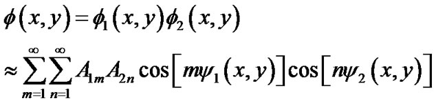
When these two optical gratings are superimposed, the resulting intensity transmission function for moiré pattern is related as follows:
 (1)
(1)
where, fi indicates the grating functions and  indicated the phase values, which show the basic shape of the grating lines; i = 1, 2. A is the coefficients determines the amplitude profile of the grating lines.
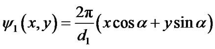
After rewriting above Equation (1), moiré patterns for different conditions can be evaluated when the grating line functions (phases) are expanded with its sinusoidal functions as follows:
 (2)
(2)
 (3)
(3)
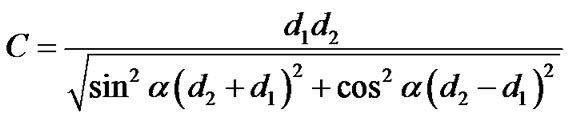
where, di indicates the line intervals of two gratings and a is the angle of each grating line created with y-axis of the coordinate system. As the sum and difference patterns are available in the above grating line functions, it represents the moiré patterns when it superimposed. Furthermore, the beat wavelength equation can be evaluated when the difference of these two grating functions (Equations (2)-(3)) is calculated. Thus, from the calculated beat wavelength functions, the general equations for calculating interval of moiré fringes as well as its angle with the vertical axis (y-axis) can be explained by the following expressions:
 (4)
(4)
 (5)
(5)
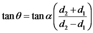
where, d1 and d2 are the intervals of two stripes. The classical examples of moiré patterns generated by the superposing of two gratings as explained above are shown in Figure 1. Figure 1(a) indicates the moiré patterns for the interference of two gratings with same grating-spaces where as, Figure 1(b) indicates the moiré fringe pattern for the interference of two gratings with different grating-spaces. The spacing of moiré fringes is indicated by C when, the angle that the moiré fringe generates with the vertical axis is indicated by q.
The rotational angle of the gratings is indicated by 2a. B and D indicate the bright and dark fringes respectively. From Equation (5), it is seen that if the intervals of two gratings are same, the angle that the moiré fringe generates with the vertical axis is 90 degrees, however, when they are not similar they generates acute angle with the vertical axis. These results can be seen in Figures 1(a) and (b) as well.
 (a)
(a) (b)
(b)
Figure 1. Moiré images with two gratings (2 wave image).
3. Experimental Procedure
3.1. Experimental Set-Up
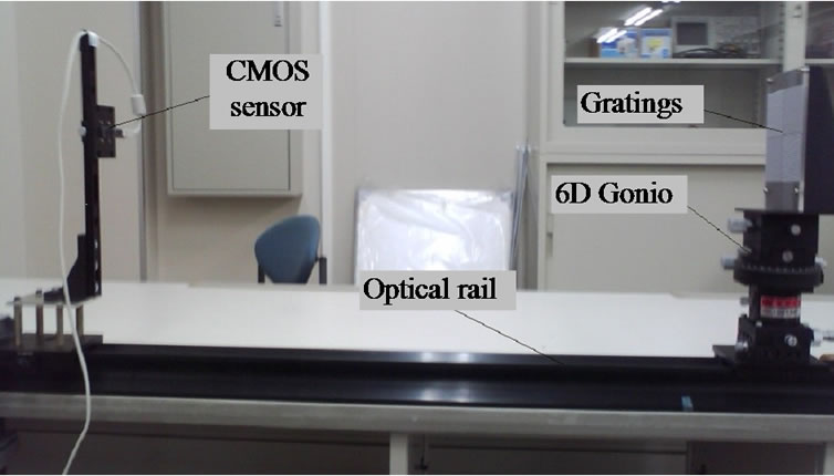
An experimental set-up has been developed capable of measuring the 6D motion of an object by using of a single gratings moiré fringe technique. Moiré fringes have been generated by applying a simple vertical straight line pattern with a grating interval of 0.71 mm. The optical gratings are designed by AR-CAD soft-wear and are printed by an inkjet canon printer (PIXUS iX7000) on to the adhesive printing paper which can be attached to an acryl board without making any air-gap. The acryl board was attached to a gonio which can move with 6 degrees of freedom (TSF60-EC, SIGMA KOKI Cor. Ltd., Japan). A small CMOS camera (MCM 4601; small CMOS sensor [5] of MICRO VISION Co. Ltd.) with 6.35 mm (1/4 inch) optical format and 2.8 μm × 2.8 μm pixel size has been used and mounted on a height adjustable stand and it is connected to a personal computer (PC) by USB cable for storage of images for further analysis. The camera-stand and the gonio-stand are mounted on an optical rail upon which all the base positions can be precisely measured. The center heights of both the camera and grating-object are kept same from the top of the rail at the beginning of the experiment. The panoramic view of the experimental setup is shown in Figure 2. The properties of CMOS camera, consisting of an integrated circuit and array of pixel sensors (photodetector and active amplifier), are shown in Figure 3 and Table 1 respectively.
The data acquisition and modulation of moiré images through the CMOS camera are conducted by OpenCV (Intel Open Source Computer Vision Library) algorithm inside the PC.
3.2. Experimental Procedure
According to the objective of the experimental set-up for motion sensing by moiré fringe with a CCD camera and a single strip, the experimental approach has been designed and executed. In the model experiment of the present approach, moiré fringes have been constructed by moving the striped-body through the angular range of 0 degree to 12 degrees with an interval of 1 degree. In all
 (a)
(a)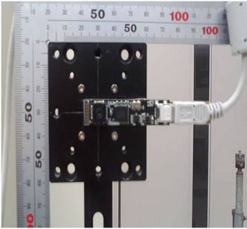 (b)
(b) (c)
(c)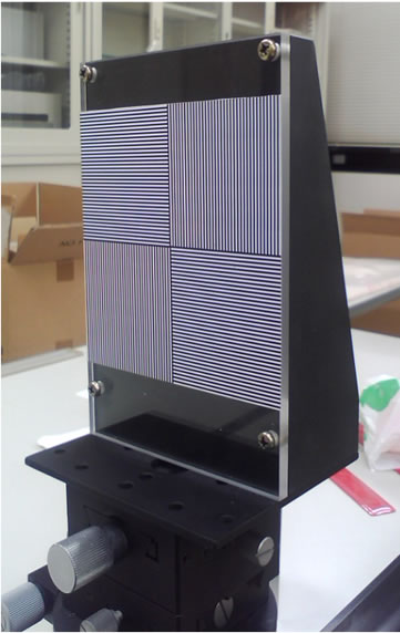 (d)
(d)
Figure 2. Experimental apparatus: (a) Aerial view of model experiment; (b) CMOS camera sensors; (c) Line gratings; (d) 6D gonio with gratings.
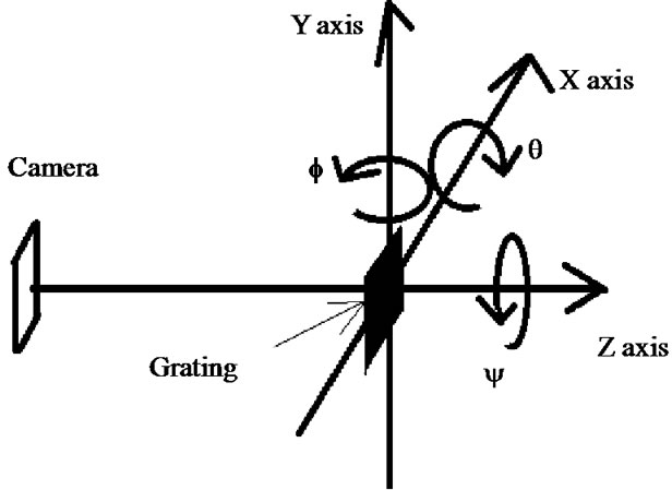
Figure 3. Coordinates specification for the 6D gonio’s motions.

Table 1. Specification of CMOS camera
experiments, the position of the camera has been kept constant. The distance between the camera and the object has not been analyzed for its detail effects in the experimental results; however, the position of the gonio (the position of the object) has been verified for getting clear fringe images and overcoming the effects of camera artifacts on images. Thus, experimental images for four positional distances as 750 mm, 900 mm, 950 mm and 1000 mm have been taken in the present measurement technique of angular motion.
Furthermore, the calculation and the measurement procedures of moiré fringe in the present short-cut method are summarized in following flowchart (Figure 4). Although, in conventional method, calculations of fringe parameters (C and q) are sometimes complicated and time consuming, in the present system it has become easier and simple. Only by selecting three points on two neighboring fringes (interval of which be calculated) of the experimental image in computer screen by mouse clicking options, the value of fringe interval as well as fringe inclination are saved in a separate result sheet automatically. The algorithm of this calculation is explained as follows.
First of all, the region of interest (ROI) has been cut off from the total experimental image. After that it has been magnified enough for getting accuracy in point selections for next calculations. The basic dimension of ROI in pixel is x = 80 and y = 95 and after magnification it has become 240 × 285.
From the ROI image, three points are selected randomly on two neighboring fringes; two points in on fringe and one on the other fringe. The pixel size of each point has been taken as 27 × 27 for getting average value while click point became the center. The coordinate of each point has been determined by calculating the center of gravity of each point based on moment method for pixel values as follows [8]:
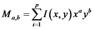 (6)
(6)
where, a, b indicate the orders of x and y respectively, I indicates the two dimensional image and p indicates the pixel values. If the values of a and b become zero, the
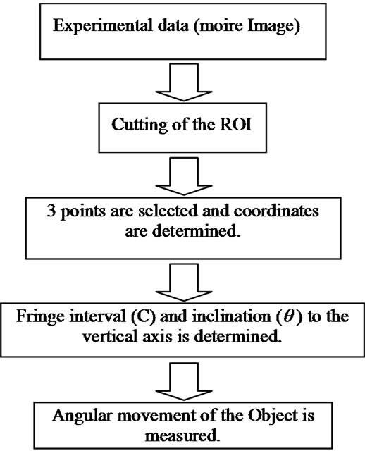
Figure 4. Algorithm of easy measurements systems of moiré parameters (C and q).
value of moment (M) becomes the length in pixels of the contour.
After determining the coordinates, two points on the same fringe are used to generate straight line by simple geometrical equation, and the third point of the neighboring fringe is used to get the perpendicular distance upon the generated straight line, and it has been used to express the interval (C) of two fringes. Again the inclination (q) of fringe has been calculated from the tangent of the straight line. After plotting the curves with these two fringe parameters, the rotational movement of the rotated object has been understood.
4. Experimental Results and Discussion
Experiments have been conducted focusing on the objective of developing a single wave moiré imaging technique for multidimensional motion sensing. In that respect the images of moiré fringe have been taken for different angular positions of the gratings acryl board. However, the camera has been kept constant in its original position. Therefore, according to the theory as explained before, the moiré fringes have been generated for different angular positions of acryl body. The angular positions have been varied from 0 degree to 12 degrees with an angular interval of 1 degree. Several images of moiré fringe for the angular positions of 2 degrees, 5 degrees, 8 degrees for the camera-body distance of 750 mm and 950 mm are shown in Figure 5.
The changes of moiré fringe patterns for the changes in angular positions are remarkably identified in Figure 4. The major changes are noticed in the interval (C) of moiré fringe and the angle (q) that the moiré fringe generates with its vertical axis. It is found, as the angular movement of the body with gratings increases, the interval
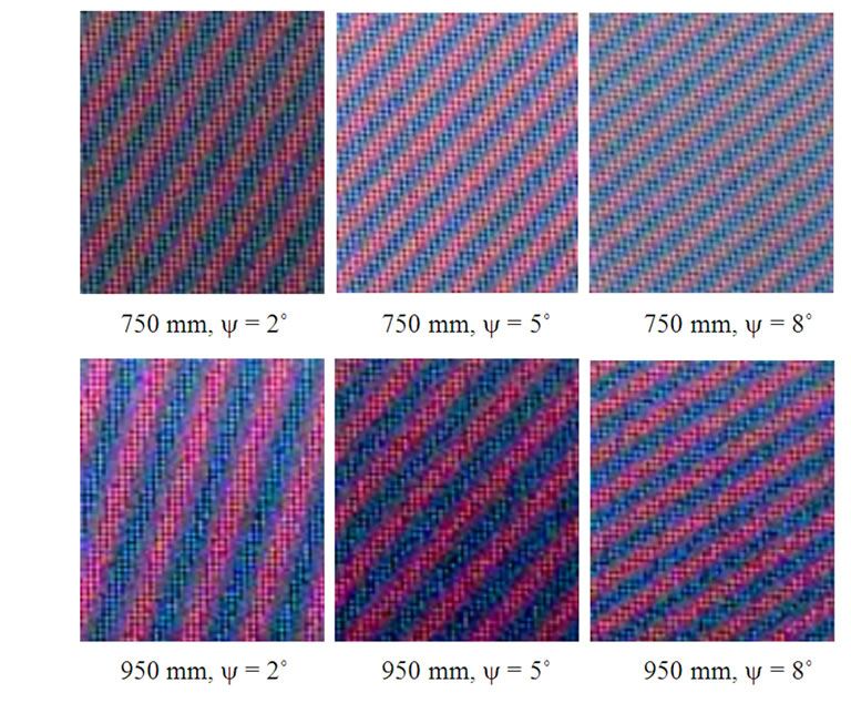
Figure 5. Moiré fringes for rotational to z-axis (y) at 2˚, 5˚ and 8˚ at a distance of 750 mm and 950 mm between camera and the rotating body.
of the moiré fringe decreases. However, concerning to the angle of moiré fringe (q), the result is opposite, which means that the fringe angle also increases when the gratings angular movement increases. Thus, these experimental results also satisfy the theoretical explanations. Therefore, by calculating fringe intervals and its angular positions simultaneously, the rotational movements of an object containing grating patterns can be identified by the proposed technique.
A lot of procedures are tried to be employed now a days to calculate these two parameters, the fringe interval as well as its angle for different places of application. For the present research, these parameters are calculated by applying the image processing techniques employing the Intell OpenCV libraries as well as some other statistical modeling. By applying the OpenCV algorithms, the accurate extraction of interested area and appropriate filtration of the moiré fringe images are conducted. The main advantage of the present method is its simplicity and quickness in moiré parameters evaluation as well as calculation. This semi-automatic (as three points are necessary to be selected manually, it is called as semi-automatic, although, all other operations for calculating the required parameters are done automatically by the proposed algorithm) algorithm based on OpenCV programming, only three points are needed to be selected on the interested moiré image. As mentioned earlier, after this selection, the result-sheet of moiré parameters will be appeared in the screen as well as will be saved to the desired location. In parameters calculation as mentioned before, cautions have been taken to its robustness in application. For example, to avoid the errors in point selection by call-back function key, averaging data of 27 × 27 pixel values have been taken. Moreover, for accuracy in selection, the ROI is magnified three times for getting accurate location. Therefore, small effects of spatial variations due to temporal variations in pointing have been truncated in the proposed algorithm. Furthermore, the errors caused by person to person in pointing has also been considered and truncated by averaging for different persons (four persons for different categories have joined randomly in getting sample data) and different timings. The uncertainly of the present auto-calculation system has also been calculated by the following methods and the result has shown that the uncertainty of calculating fringe intervals falls below 5% when the uncertainty of calculating fringe inclination to vertical axis falls below 1%. Thus it has found that the present quick and easy technique of fringe parameters calculation makes easier to measure a rotating object correctly and precisely.
The results of calculations for the intervals and angles of moiré fringes for the angular movements of the rotating body (acryl board at gonio in the experiment) are shown in Figures 6 and 7, from where the angular position of the object can be calculated as well. Moreover, it is found in the result that the calculated value differs with respect to the distance of the object from camera. In the result this effect is largely influenced for the distance of 900 mm. Although, the detail effect of this property has not been analyzed in the present research, however, it is understood that the effect of camera lens (ray theory) has
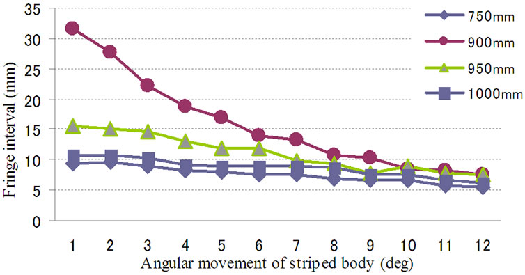
Figure 6. Moiré fringe intervals with respect to the angular movement of the measured striped body.

Figure 7. Moiré fringe intervals with respect to the angular movement of the measured striped body.
influenced the result.
5. Conclusions
Precise measurement of angular moving body by a single grating based moiré technique has been performed. Although, some artifacts due to the differences in intervals of the camera and the specimen gratings are available, however, that effects are successfully truncated in calculations of the interval and the angle of moiré fringe in the present moiré technique.
As the proposed algorithm is successfully employed in calculating the moiré fringe parameters, it has made the moiré measurement technique simple, easy and semiautomatic as well.
Although, the proposed algorithm has been verified by the straight symmetric moiré fringes, however, the parameters of other curvilinear non-symmetric fringes can also be calculated by changing the required simple geometrical equation in step 4 of the proposed algorithm.
REFERENCES
- S. A. Kamal, “Pattern Recognition Using Moire Fringe Topgraphy and Rasrerstereography,” International Symposium on Biometrics and Security Technologies, Islamabad, 23-24 April 2008, pp. 1-7.
- I. Amidror, “The Theory of the Moiré Phenomenon,” 2nd Edition, Springer, 2009. doi:10.1007/978-1-84882-181-1
- R. H. Dyck and G. P. Weckler, “Integrated Arrays of Silicon Photodetectors for Image Sensing,” IEEE Transactions on Electron Devices, Vol. 15, No. 4, 1968, pp. 196- 201.
- R. F. Eric, “Active Pixel Sensors: Are CCD’s Dinosaurs?” Proceedings of SPIE Symposium on Electronic Imaging, San Jose, 12 July 1993, pp. 2-14.
- D. Passeri, et al., “Characterization of CMOS Active Pixel Sensors for Particle Detection: Beam Test of the FourSensors RAPS03 Stacked System,” Nuclear Instruments and Methods in Physical Research Section A: Accelerators, Spectrometers, Detectors and Associated Equipment, Vol. 617, No. 1-3, 2010, pp. 573-375.
- S. S. Grothi and P. Rastogi, “Fringe Projection Techniques: Whither We Are?” Optics and Lasers in Engineering, Vol. 48, No. 2, 2010, pp. 133-140. doi:10.1016/j.optlaseng.2009.09.001
- D. Malacara, “Optical Shop Testing,” 3rd Edition, John Wiley & Sons, New Jersey, 2007. doi:10.1002/9780470135976
- J. Flusser, “Refined Moment Calculation Using Image Block Representation,” IEEE Transactions on Image Processing, Vol. 9, No. 11, 2000, pp. 1976-1978.