Open Journal of Composite Materials
Vol.4 No.1(2014), Article ID:41975,8 pages DOI:10.4236/ojcm.2014.41004
To Improve Mixed-Mode Interlaminar Fracture Toughness of Composite Sub-Structures
![]()
School of Aerospace and Aircraft Engineering, Kingston University, London, UK.
Email: *hessam.ghasemnejad@kingston.ac.uk
Copyright © 2014 Hessam Ghasemnejad, Hossein Mirzaii. This is an open access article distributed under the Creative Commons Attribution License, which permits unrestricted use, distribution, and reproduction in any medium, provided the original work is properly cited. In accordance of the Creative Commons Attribution License all Copyrights © 2014 are reserved for SCIRP and the owner of the intellectual property Hessam Ghasemnejad, Hossein Mirzaii. All Copyright © 2014 are guarded by law and by SCIRP as a guardian.
Received July 24th, 2013; revised August 24th, 2013; accepted August 30th, 2013
KEYWORDS
Delamination; Stitching; ADCB; Composite
ABSTRACT
The present paper investigates the influence of stitching on delamination resistance of laminated composite structures. The mixed-mode interlaminar fracture toughness, GI/IIC, of the stitched hybrid laminated composites is studied in order to investigate the resistance of the 3D-composites to the crack propagation in delaminated composite structures. To that end, the mixed-mode interlaminar fracture toughness was measured using the asymmetric double cantilever beam (ADCB) test method. The hybrid ADCB and stitched hybrid ADCB composite beams were laid-up in order to study the effect of stitching on the interlaminar fracture toughness. The test results showed that the resistance of stitched fibres against the crack propagation in stitched hybrid composites can significantly improve the mixed-mode interlaminar fracture toughness.
1. Introduction
The fibre-reinforced polymer (FRP) composite materials provide functional and economic benefits such as enhanced strength, durability, and stiffness to weight ratio. This could also result in a net environmental benefit in terms of lower fuel consumption and CO2 emission. Composites are the preferred materials in a variety of industrial applications. Although they are primarily used in aerospace structures, they are also the materials of choice in such diverse applications as the marine engineering, automotive structural parts, micro-electro-mechanical systems, wind turbine blades as well as stiffeners for civil structures. In this regard, it is important to investigate such advanced composite materials as 3DFRP composites with a view to improving their mechaniccal and physical properties further compared to the 2DFRP composites.
Although composites do not experience metal-like fatigue failure, laminated composites are, nevertheless, prone to failure by delamination. This not only can occur during the manufacturing process due to such factors as voids and trapped gas, contaminated reinforcing fibres, insufficient wetting of fibres and machining operations, but it could also occur during the service due to impact shocks or environmental degradation, particularly moisture intake. Furthermore, under transverse mechanical loading, interlaminar stresses are induced which, owing to the substantial difference between the resin and fibre moduli results in a correspondingly large straining of the resin. In the absence of any through-thickness reinforcement, this could lead to delamination. Extensive study of the delamination resistance has led to the development of various test methods [1-8]. Standards are currently available for the mode-I double cantilever beam (DCB), mode-II end notched flexure (ENF) and mixed-mode bending (MMB) tests on unidirectional (UD) laminates. However, most of the laminate designs of composite structures involve multidirectional (MD) laminates, and delamination usually occurs at the interfaces between differently oriented plies.
Choi et al. [9] investigated the fixed ratio mixed mode test (GI/GII = 4/3) on carbon/epoxy UD and [45/−45] specimens. Intraply damage occurred in the latter, but it was possible to obtain true interlaminar values for the initiation total critical strain energy release rate Gc. These values were 65% higher than those of UD specimens. Ozdil and Carlsson [10,11] tested glass/polyester and filament wound glass/epoxy MMB specimens and obtained θ-increasing initiation Gc values. Kim and Mayer [12] evaluated the toughness of carbon/epoxy MMB specimens with various delaminating interfaces. Initiation occurred already in an in tralaminar non-self-similar move towards a neighbouring interface. Furthermore, the area method employed for data reduction seems unsuited, as suggested by the very low toughness values reported. Pereira and Morais [13] performed the MMB tests on glass/epoxy multidirectional specimens with delamination in (0/θ) and (θ/−θ) type interfaces. In their study, the modified beam theory (MBT) data reduction scheme gave accurate predictions of specimen compliances. Oliveira et al. [14] undertook to verify numerically the adequacy of the MMB method for fracture characterisation of clear wood from maritime pine under mixed-mode loading. The results of numerical simulations were used as input data in a new data reduction scheme based on specimen compliance. Wosu et al. [15] used the mixed-mode open notched flexure (MONF), anti-symmetrically loaded endnotched flexure (MENF) and centre-notched flexure (MCNF) specimens to investigate the dynamic mixed I/II mode delamination fracture using a fracturing split Hopkinson pressure bar. The experimental results showed that dynamic delamination increases linearly with mode mixing. Also at higher impact energy (E ≤ 0.4 J), the dynamic (Gd) and total (GT) energy release rate is independent of the mixed-mode ratio. Dharmawan et al. [16] studied the mixed mode loading conditions ranging from a mode mix ratio (GII/GT) of 0% using DCB test, through the mixed mode range, using MMB tests, to 100%, using ENF testing for thick glass/vinylester specimens. There was a significant difference between the results for 0% mode mix ratio as measured using the DCB test and those for 20% mode mix ratio as measured by the MMB test, even when adjusted according to the exponential trend line. Rugg et al. [17] investigated the mixed-mode delamination behaviour of carbon-epoxy laminates, which had been reinforced through-thickness, using two different test specimens, T-stiffener and a mixed-mode bending (MMB) specimen. Their results indicate that reinforcement raises the ultimate strength of the MMB specimen by a factor of three. However, the failure sequence and, therefore, the ultimate load in the T-stiffeners depend strongly on the test configuration.
The fixed ratio mixed mode asymmetric double cantilever beam (ADCB), studied extensively by the ESIS TC4 group in the 1990s, is limited as it is a single ratio of 4:3 of mode I to mode II component. The ADCB-test requires a sliding fixture similar to the mode II ELS-test. Locus plots with pure mode I, pure mode II and mixed mode I/II can thus be generated with two test rigs (DCB and sliding fixture for ELS and ADCB) or, alternatively, with three rigs (DCB, 4ENF, and MMB) [18].
In the present work, the mixed-mode interlaminar fracture toughness, GI/IIC, of stitched hybrid laminated composites is studied in order to investigate the behaviour of 3D-composites under the condition of crack propagation experienced by delaminated composites. The mixed-mode interlaminar fracture toughness, GI/IIC, was measured using asymmetric double cantilever beam (ADCB) test method.
The hybrid ADCB and stitched hybrid ADCB composite beams were laid-up from [G0/C0]10, [G0/C90]10, [G90/C0]10 and [G90/C90]10 to study the effect of stitching on the interlaminar fracture toughness. Test results showed that the resistance of stitched fibres against the crack propagation in the stitched hybrid composites can significantly increase the mixed-mode interlaminar fracture toughness.
2. Experimental Study
The mechanical characteristics of carbon/epoxy and glass/ epoxy were obtained in accordance with the relevant standards. These tests are included tensile, shear, fibre volume fraction [19-21], coefficient of friction, double cantilever beam (DCB), 3-point-end-notched flexure (3ENF) and asymmetric double cantilever beam (ADCB). All specimens were manufactured from carbon fibre reinforced plastic (CFRP) and glass fibre reinforced plastic (GFRP) materials of density 1.8 g/cm3 and 1.6 g/cm3 respectively, with epoxy resin as matrix. A summary of the findings for tensile, shear and fibre volume fraction are tabulated in Table 1.
2.1. Preparation of Hybrid ADCB Specimen
The lamination of the ADCB beam consisted of 20 layers of GFRP and CFRP (total thickness of 5.5 mm). The mid-plane interfaces were G0//C0, G0//C90, G90//C0 and

Table 1. Material properties of the unidirectional CFRP and GFRP composites.
G90//C90 to determine the mixed-Mode I/II interlaminar fracture toughness along the fracture planes. For determining the mixed-Mode I/II interlaminar fracture toughness, GI/IIC, ESIS protocol [4] was followed. A Teflon insert of thickness 13 μm was located at the midplane in the ADCB specimens. The insert position was applied at the mid-plane (10//10) of specimen with equal arm thickness h1 = h2 = 2.75 mm (see Figure 1). The corrections for the end-block, ADCB arm bending and root rotation were considered. According to the reference [4], the recommended ADCB specimen size is at least 160 mm long and 20 mm wide with an initial precrack length (i.e. the length of the insert from the load line) of 45 mm. Force at each crack length was retrospectively obtained from the recorded force-displacement diagram to calculate the GI/IIC of ADCB specimens (see Figure 2).
2.2. Preparation of Stitched Hybrid ADCB Specimen
Many novel techniques [22] have been developed to reinforce laminated polymer composites in the throughthickness direction as a solution to the problems of poor impact damage tolerance, low through-thickness mechaniccal properties, and weak strength of bonded joints. The most common through-thickness reinforcement techniques are 3D weaving, stitching and braiding. More specialist techniques include embroidery, tufting and z-anchoring, hereafter known as stitching. These techniques are effective at increasing the delamination resistance and impact damage tolerance. The manufacturing of stitched hybrid composite specimens is similar to the normal hybrid composite specimens except that subsequent to the laying up of the laminate, the stitched ADCB specimens have to be stitched with Glass fibres (see Figure 3(a)) before moulding.

Figure 1. The ADCB specimen used for the mixed-Mode I/II delamination tests (All dimensions in mm).


Figure 2. The force-load line displacement from the symmetric and asymmetric ADCB tests.
 (a)
(a) (b)
(b) (c)
(c)
Figure 3. The manufacturing process of stitched composite specimen, (a) Stitching Glass fibres; (b) Stitched laminated composite; and (c) Typical geometry of ADCB beam after stitching.
Strips of glass fibres were stitched onto the test specimens in the z-direction using a needle. For each specimen, three rows of stitches, each row containing nine pins, were stitched. To ensure uniform crack propagation in the test specimens, these pins were placed at a distance of 10 mm past the Teflon insert. Also, with each row being 10 mm apart, the nine pins were stitched such that there were three rows in total and three pins in each row (see Figure 3(b)). The recorded force-displacement diagrams are shown in Figure 4.
3. Experimental Results and Discussion
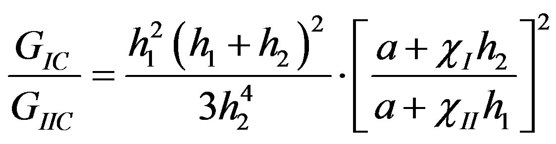
Various test methods have been investigated to measure mixed-Mode I/II interlaminar fracture toughness. The mixed-mode bending (MMB) test has been balloted within ASTM as a prospective mixed-mode standard. The main advantage of the MMB test is that it could change the whole mixed-mode failure envelope from pure Mode-I to pure Mode-II, which can be measured using a single apparatus. The asymmetric double cantilever beam (ADCB) is another test method for measuring the mixed-Mode I/II interlaminar fracture toughness. The ADCB test method yields one single ratio, namely GIC/GIIC, which is equal to 4/3 between Mode I and Mode II interlaminar fracture toughness.
The mixed-mode ratio of ADCB specimen can be calculated from
 (1)
(1)
where h1 is the distance between the plane of insert film and the top of the beam and h2 is the distance from the plane of insert film to the bottom of the beam and
 (2)
(2)
where  is a correction factor for the beam root rotation in Mode-I component, and
  is the correction factor for Mode-II component.
The mixed-mode ratio of ADCB specimen which was made with Teflon insert at the mid-plane (h1 = h2), was 1.33.
Using the Corrected Beam Theory (CBT) method, which uses simple beam theory with correction factors accounting for the beam not being perfectly built-in and having a large displacement during the test, the total mixed-Mode I/II energy release rate in the ADCB test, GI/IIC, can be partitioned to Mode-I and Mode-II components as [19]:
 (3)
(3)
where  and
and  are as below,


Figure 4. The force-load line displacement from the symmetric and asymmetric stitched-ADCB tests.
 (4)
(4)
 (5)
(5)
in which f is the large displacement correction factor.
In this study Experimental Calibration Method (ECM) which uses the plot of the compliance, C, versus the cube of the delamination length, a3, was also considered to determine the mixed-Mode I/II fracture toughness.
There are three different methods for determining the crack length for the initiation values from the precrack as the distance between the force-displacement and the precrack are considered. The first non-linearity (NL) method determines the point of deviation from linearity, by sketching a straight line from the origin. The second uses the visual observation (VIS) which is the first point at which the crack is observed to move from the tip of the Teflon insert. The last method is the MAX/5%, a point on the force-displacement curve at which the compliance has increased by 5% of its initial value. Since no significant difference is expected to exist between any two of these methods, in this work the visual observation (VIS) was conveniently chosen to determine the initiation crack length. The comparison between force-displacement for the ADCB and the z-ADCB for laminate design of [C90/G0]10 specimen is shown in Figure 5. Subsequent to the appearance of the crack in the stitched area in the z-ADCB specimen, load increases rapidly in comparison with the variation of load in other ADCB specimens. Beside the stitching effect, the development of the transverse cracking caused several continuous increases of force after the initial crack propagation, resulting in a rising R-curve for the ADCB specimens. Transverse cracking for all the interface planes happened at the beginning of the delamination growth (see Figure 6). Reasons such as intra-laminar delamination, mixed mode fracture, fibre-bridging, micro-cracking, residual stresses, or a combination of these in the θ-oriented lamina at the interface are believed to have caused the development of transverse cracking in the ADCB tests (see Figure 7). In all the ADCB tests, intra-laminar delamination, fibre-matrix debonding and/or fibre breakage were observed in fracture surface areas as shown in Figures 8 and 9.
The results of mixed-Mode I/II delamination fracture toughness, GI/IIC, using VIS for each interface, are presented in Table 2. According to the standard [4],

Figure 5. The force-load line displacement from (a) ADCB; and (b) Stitched (z-ADCB) tests for mid-plane interface of C90//G0.

Figure 6. Typical crack propagation in the mixed-Mode I/II (GI/GII) delamination at the fracture plane interface before the stitched area.
 (a)
(a)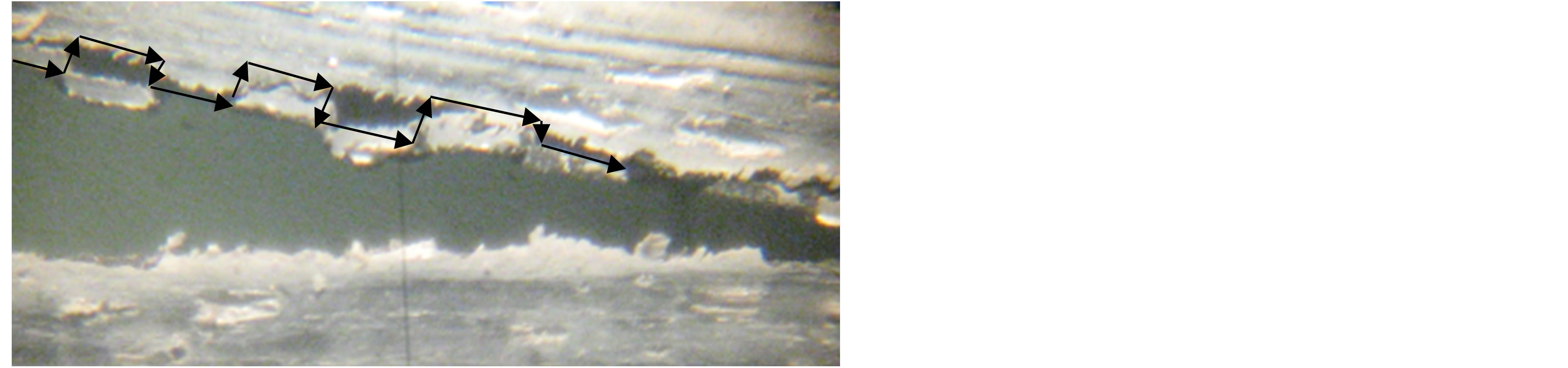 (b)
(b)
Figure 7. Transverse cracking in the ADCB specimen at the crack tip with a typical pattern of crack propagation, (a) ADCB specimen; and (b) Transverse cracking at the crack tip.

Figure 8. Optical micrograph from fracture surface of the hybrid ADCB specimens showing fibre breakage of the intralaminar C90//G0 interface.

Figure 9. Crack propagation in the stitched ADCB specimen.
mixed-Mode I/II tests have to be complemented by pure Mode I and Mode II tests, if the full failure envelope is to be determined. Thus, Mode-I (GIC) and Mode-II (GIIC) interlaminar fracture toughness was also measured with the same fracture interfaces. The experimental resistance curve of GI/IIC versus crack length for laminate design of the stitched-ADCB specimen of [C90/G0]10 is presented in Figure 10. Results showed that the resistance of stitched fibres against the crack propagation in the stitched hybrid composites can significantly increase the mixed-mode interlaminar fracture toughness (see Figure 11).

Table 2. Interlaminar fracture toughness obtained from the ADCB and stitched (z-ADCB) tests.

Figure 10. The resistance curve (R-curve) in the stitched (zADCB) specimens with the C90//G0 fracture plane interfaces using the CBT method.
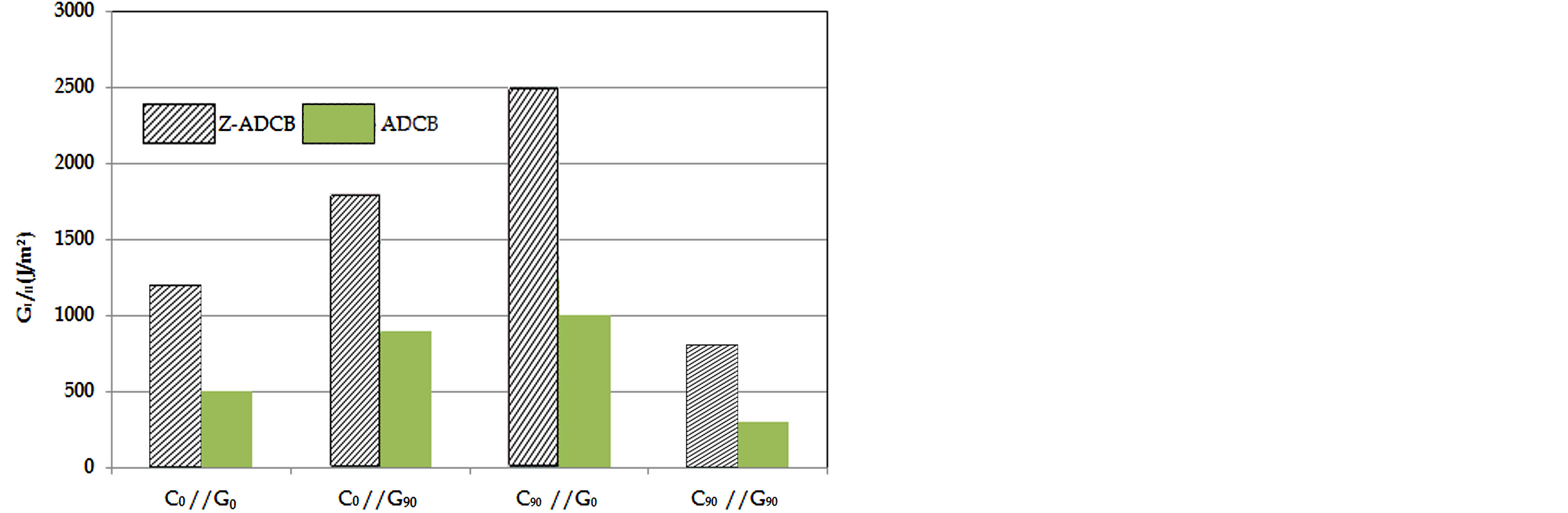
Figure 11. Comparison of propagation values of mixedmode interlaminar fracture toughness, GI/IIProp, of various laminate designs using the ECM method.
4. Conclusions
In this work, the mixed-mode interlaminar fracture toughness, GI/IIC, of the stitched hybrid laminated composites was studied in order to investigate the resistance of the 3D-composites to the crack propagation in delaminated composite structures. The mixed-mode interlaminar fracture toughness, GI/IIC, was measured using asymmetric double cantilever beam (ADCB) test method.
The hybrid ADCB and stitched hybrid ADCB composite beams were laid-up according to the configurations [G0/C0]10, [G0/C90]10, [G90/C0]10 and [G90/C90]10 in order to study the effect of stitching on the interlaminar fracture toughness. Results showed that the resistance of stitched fibres against the crack propagation in the stitched hybrid composites can significantly increase the mixedmode interlaminar fracture toughness.
REFERENCES
- BS EN ISO 15024:2001, “Fibre-Reinforced Plastic Composites. Determination of Mode I Interlaminar Fracture Toughness, GIC, for Unidirectional Reinforced Materials,” BSI, 2002.
- T. E. Tay, “Characterization and Analysis of Delamination Fracture in Composites: An Overview of Developments from 1990 to 2001,” Applied Mechanics Reviews, Vol. 56, No. 1, 2003, pp. 1-31. http://dx.doi.org/10.1115/1.1504848
- P. Davies, B. R. K. Blackman and A. J. Brunner, “Standard Test Methods for Delamination Resistance of Composite Materials: Current Status,” Applied Composite Materials, Vol. 5, No. 6, 1998, pp. 345-364. http://dx.doi.org/10.1023/A:1008869811626
- D. R. Moore, A. Pavan and J. G. Williams, “Fracture Mechanics Testing Methods for Polymers, Adhesives and Composites,” Elsevier Science Ltd., Amsterdam, 2001.
- B. R. K. Blackman, A. J. Kinloch and M. Paraschi. “The Determination of the Mode II Adhesive Fracture Resistance, GIIc, of Structural Adhesive Joints: An Effective Crack Length Approach,” Engineering Fracture Mechanics, Vol. 72, No. 6, 2005, pp. 877-897. http://dx.doi.org/10.1016/j.engfracmech.2004.08.007
- B. R. K. Blackman, A. J. Kinloch and J. G. Williams, “Mode-II Fracture Testing of Composites: A New Look at an Old Problem,” Engineering Fracture Mechanics, Vol. 73, No. 16, 2006, pp. 2443-2455. http://dx.doi.org/10.1016/j.engfracmech.2006.05.022
- ASTM D 6671-01, “Standard Test Method for Mixed Mode I/II Interlaminar Fracture Toughness of Unidirectional Fibre Reinforced Polymer Matrix Composites.”
- A. J. Kinloch, Y. Wang, J. G. Williams and P. Yayla, “The Mixed-Mode Delamination of Fibre Composite Materials,” Composites Science and Technology, Vol. 47, No. 3, 1993, pp. 225-237. http://dx.doi.org/10.1016/0266-3538(93)90031-B
- N. S. Choi, A. J. Kinloch and J. G. Williams, “Delamination Fracture of Multidirectional Carbon-Fibre/Epoxy Composites Under Mode I, Mode II and Mixed-Mode I/II Loading,” Journal of Composite Materials, Vol. 33, No. 1, 1999, pp. 73-100. http://dx.doi.org/10.1016/0266-3538(93)90031-B
- F. Ozdil and L. A. Carlsson, “Beam Analysis of AnglePly Laminate Mixedmode Bending Specimens,” Composites Science and Technology, Vol. 59, No. 6, 1999, pp. 937-945. http://dx.doi.org/10.1016/S0266-3538(98)00128-6
- F. Ozdil and L. A. Carlsson, “Characterization of Mixed Mode Delamination Growth in Glass/Epoxy Composite Cylinders,” Journal of Composite Materials, Vol. 34, No. 5, 2000, pp. 420-441.
- B. W. Kim and A. H. Mayer, “Influence of Fiber Direction and Mixed-Mode Ratio on Delamination Fracture Toughness of Carbon/Epoxy Laminates,” Composites Science and Technology, Vol. 63, No. 5, 2003, pp. 695- 713.
- A. B. de Morais and A. B. Pereira, “Mixed Mode I + II Interlaminar Fracture of Glass/Epoxy Multidirectional Laminates—Part 2: Experiments,” Composites Science and Technology, Vol. 66, No. 13, 2006, pp. 1896-1902. http://dx.doi.org/10.1016/j.compscitech.2006.04.006
- J. M. Q. Oliveira, M. F. S. F de Moura, M. A. L. Silva and J. J. L. Morais, “Numerical Analysis of the MMB Test for Mixed-Mode I/II Wood Fracture 2,” Composites Science and Technology, Vol. 67, No. 9, 2007, pp. 1764- 1771. http://dx.doi.org/10.1016/j.compscitech.2006.11.007
- S. N. Wosu, D. Hui and P. K. Dutta, “Dynamic MixedMode I/II Delamination Fracture and Energy Release Rate of Unidirectional Graphite/Epoxy Composites,” Engineering Fracture Mechanics, Vol. 72, No. 10, 2005, pp. 1531-1558. http://dx.doi.org/10.1016/j.engfracmech.2004.08.008
- F. Dharmawan, G. Simpson, I. Herszberg and S. John, “Mixed Mode Fracture Toughness of GFRP Composites,” Composite Structures, Vol. 75, No. 1-4, 2006, pp. 328- 338. http://dx.doi.org/10.1016/j.compstruct.2006.04.020
- K. L. Rugg, B. N. Cox and R. Massabo, “Mixed-Mode Delamination of Polymer Composite Laminates Reinforced through the Thickness by z-Fibres,” Composites Part A: Applied Science and Manufacturing, Vol. 33, No. 2, 2002, pp. 177-190. http://dx.doi.org/10.1016/S1359-835X(01)00109-9
- P. Davies (Editor), “Protocols for Interlaminar Fracture Testing of Composites,” ESIS-Polymers and Composites Task Group, 1993.
- BS EN ISO 2747, “Glass Fibre Reinforced Plastics-Tensile Test,” British Standard Institute, London, 1998.
- BS EN ISO 14129, “Fibre Reinforced Plastics Composite-Determination of the In-plane Shear Stress/Shear Strain Response, Including the In-plane Shear Modulus and Strength by the ±45 Tension Test Method,” British Standard Institute, London, 1998.
- ASTM D 3171-99, “Standard Test Method for Constituent Content of Composite Materials,” Annual book of ASTM Standards, West Conshohocken, 2002.
- L. Tong, A. P. Mouritz and M. Bannister, “3D Fibre Reinforced Polymer Composites,” Elsevier, Amsterdam, 2002.
Nomenclature
α: crack length
αe: effective crack length B: width of ADCB specimen C: compliance E: Young’s modulus E1: flexural Modulus f: large displacement correction factor F: force G12: shear modulus GI/IIC: mixed-Mode-I/II interlaminar fracture toughness LF: free length of the specimen S: shear strength Vf: fibre volume fraction v: Poisson’s ratio
σu: ultimate tensile stress
σb: flexural strength
τs: shear strength
NOTES
*Corresponding author.