Open Journal of Composite Materials
Vol.3 No.2(2013), Article ID:29823,13 pages DOI:10.4236/ojcm.2013.32006
Effects of Boundary Conditions on Postbuckling Strengths of Composite Laminate with Various Shaped Cutouts under In-Plane Shear
![]()
1Department of Mechanical Engineering, Malaviya National Institute of Technology (MNIT), Jaipur, India; 2Department of Civil Engineering, Birla Institute of Technology and Science (BITS), Pilani, India.
Email: *sbsingh@pilani.bits-pilani.ac.in
Copyright © 2013 Dinesh Kumar, Shamsher Bahadur Singh. This is an open access article distributed under the Creative Commons Attribution License, which permits unrestricted use, distribution, and reproduction in any medium, provided the original work is properly cited.
Received January 16th, 2013; revised February 10th, 2013; accepted March 10th, 2013
Keywords: Boundary Conditions; Buckling; Postbuckling; Cutouts; Composite Laminate; FEM
ABSTRACT
Cutouts are often provided in composite structural components for practical reasons. For instance, aircraft components such as wingspar, fuselage and ribs are provided with cutouts for access, inspection, fuel lines and electric lines or to reduce the overall weight. This paper addresses the effect of boundary condition on buckling and postbuckling responses, failure loads, and failure characteristics of composite laminate with various shaped cutouts (i.e., circular, square, diamond, elliptical-vertical and elliptical-horizontal) and having different lay-ups under in-plane shear (positive and negative) load, using finite-element method. The FEM formulation is based on the first order shear deformation theory in conjunction with geometric nonlinearity using von Karman’s assumptions. The 3-D Tsai-Hill criterion is used to predict the failure of a lamina while the onset of delamination is predicted by the interlaminar failure criterion. It is observed that the effect of boundary condition on buckling, first-ply failure and ultimate failure loads of a quasi-isotropic laminate with cutout is more for positive shear load than that for the negative shear load for almost all cutout shapes. It is also noted that under in-plane shear loads postbuckling stiffness of (0/90)4s laminate with circular cutout is maximum, while it is minimum for (45/−45)4s laminate with circular cutout, irrespective of boundary conditions.
1. Introduction
Currently, thin composite laminated panels are used in almost all modern advanced engineering applications such as spacecraft, high speed aircrafts, naval vessels and automobiles because of their superior specific properties (i.e., stiffness-to-weight and strength-to-weight ratios) as compared to their metallic counterparts. Further, cutouts are often provided in these panels for practical considerations. For instance, cutouts in wing spars and cover panels of commercial transport wings and military fighter wings are provided to form ports for mechanical and electrical systems, damage inspection, fuel lines, and also to reduce the overall weight of the composite structure. The presence of these cutouts forms free edges in the composite laminates under various loading and boundary conditions, which in turn cause high interlaminar stresses [1] leading to loss of stiffness and premature failure of laminate owing to delamination. These composite structural laminates with cutouts are required primarily to resist buckling, and they must carry a load well into the postbuckling range to yield weight savings by utilizing its reserve strength beyond buckling. Further, boundary conditions affect the buckling and postbuckling behavior of laminated panels under various loading conditions such as in-plane compression, shear, and combined inplane shear and compression [2-6]. In addition, the shear directions also affect the postbuckling behavior of composite plates [7,8]. Thus, it is imperative to have thorough knowledge of buckling, postbuckling, failure characteristics and strength of thin composite panels with cutouts under various edge boundary conditions subjected to in-plane shear (positive and negative) loads, for their cost effective and efficient design.
A comprehensive review on buckling and postbuckling behavior of laminated composite plates with a cutout by Nemeth [9] has shown that only limited works [10-13] are available on buckling and postbuckling behavior of laminated composite panels with cutouts under shear loads for different boundary conditions. Moreover, these studies are primarily for laminates with central circular cutouts. Thereafter, Jha and Kumar [14] studied the firstply failure of symmetric square laminates (without cutouts) under the combined effect of in-plane and transverse loads using FEM. Jain and Kumar [15] examined the effect of cutout shape, size and the alignment of the elliptical cutout on the buckling and the first-ply failure loads of laminates under uni-axial compression. Guo [16] conducted numerical and experimental studies to investigate the effect of reinforcements around cutouts on the stress concentration and buckling behaviour of a carbon/ epoxy composite panel with simply-supported and clamped boundary conditions under in-plane shear load. Guo et al. [17] examined the effect of cutout and various edge reinforcements in a composite C-section beam under static shear load and demonstrated that the cutout induced stress concentration can be reduced significantly by appropriate cutout shape and edge reinforcements. Very lately, Kumar and Singh [18] studied the buckling and postbuckling response and strengths of simply-supported composite laminate with various shaped cutouts under inplane shear.
From the above literature review, it is manifested that there are no investigations on the effects of boundary conditions on buckling and postbuckling behavior of composite laminates with non-circular cutouts under in-plane shear loading conditions. Furthermore, most of the available studies on shear buckling and postbuckling of laminates with cutouts under given boundary conditions are mainly concerned with the study of load versus out-ofplane displacement relationship at loads beyond buckling without commenting on their actual reserve strength in the postbuckling range. The aim of the present investigation is to explore the effect of boundary condition on buckling and postbuckling responses, failure loads and failure characteristics of a quasi-isotropic [i.e., (+45/− 45/0/90)2s] laminate with central circular as well as noncircular (i.e., square, diamond, elliptical) cutouts under in-plane positive and negative shear loads. In addition, for various boundary conditions, the effect of the composite lay-up on buckling and postbuckling characteristics of the laminate with a circular cutout is also studied by taking three most practical laminate configurations, namely, quasi-isotropic [i.e., (+45/−45/0/90)2s], angle-ply [i.e., (45/−45)4s], and cross-ply [i.e., (0/90)4s].
2 Present Study
2.1. Finite Element Formulation
A special-purpose computer program is developed to carry out the study which is based on the finite-element formulation using the first-order shear deformation theory with a nine-noded Lagrangian element having five degrees of freedom per node. Geometric non-linearity based on von Karman’s assumptions has been incorporated. The formulation is based on the virtual work equation for a continuum in the total Lagrangian coordinate system under the assumption of small strains.
The displacement within an element is interpolated by an expression of the form
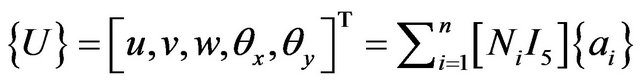 ;
;
where  is the value of displacement components at a point within an element; n the number of nodes in an element; Ni the shape functions of a nine noded Lagrangian element, for i = 1, n; I5 the 5 × 5 unit matrix;
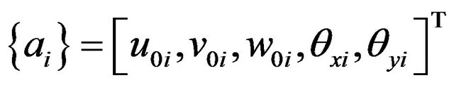 is the nodal displacement vector for ith node.
From the principle of virtual work and the total Lagrangian formulation, the element nonlinear equilibrium equation is derived as:
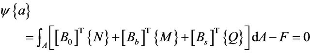
where  is the residual force which is a function of displacement vector
 ;
;  the straindisplacement matrices corresponding to in-plane axial, bending and shear strains, respectively;
 ![]() the stress resultants per unit length;
the stress resultants per unit length;  the moment resultants per unit length;
  the transverse shear stress resultants per unit length; F the external applied loads (includes in-plane loads as well as transverse forces).
The Newton-Raphson method is used to solve these nonlinear algebraic equations using a combined incremental and iterative procedure. If for an initial estimate of  (i.e., for jth iteration), the residual forces
  then an improved solution
  is obtained by equating to zero the linearized Taylor’s series expansion of
  in the neighborhood of
  as
as
![]()
where  is the incremental displacement vector and KT is the tangent stiffness matrix evaluated at
  and is given by:

The improved solution is then found as:
 .
.
To improve on the numerical stability and convergence of the solution, the load is applied in small increments. The iterative solution is checked for convergence using the following criterion:

where is sufficiently small number, i.e., 0.001%.
The integration of expressions for  and KT is carried out using the Gaussian quadrature. A selective integration scheme is adopted with
  integration rule to evaluate integrals of the functions of the membrane and the bending behavior and
  integration rule is used for the transverse shear component.
2.2. Failure Model and Definition of Failure
Failure of a lamina is predicted by tensor polynomial form of the 3-D Tsai-Hill criterion [19], [see Appendix (1)], wherein five stress components in material directions (three in-plane stresses and two transverse shear stresses) were calculated at mid thickness of each layer of individual element using the constitutive equations and by applying proper transformation. In addition, an attempt has been made in the present study to predict the onset of delamination at interface of two adjacent layers using interlaminar failure criterion [20], [see Appendix (2)]. Three transverse stresses at each gauss point on the corresponding interface are calculated in material directions using integration of equilibrium equations and by applying proper transformation. The in-plane stress variations used in each equilibrium equation are derived from nodal values of in-plane stresses. To predict the ultimate failure of laminate, a progressive failure procedure as used by Singh and Kumar [8] has been implemented. In this progressive failure procedure, at each load step, gauss point stresses are used in tensor polynomial form of the Tsai-Hill failure criterion. If failure occurs at a gauss point in a layer of an element, a reduction in the appropriate lamina stiffness is introduced in accordance with the mode of failure. The laminate stiffness is recomputed and failure is checked again at the same load step. If no failure occurs, the process is repeated at next load step. Ultimate failure is said to have occurred when the onset of delamination occurs at interface of any two layers of any element or when the plate is no longer able to carry any further increase in load due to large transverse deflection.
2.3. Material Properties and Geometric Model
Properties of the material (T300/5208 graphite epoxy) of each lamina are presented in Table 1. A full square laminate of size 279 mm 279 mm × 2.16 mm with ply thickness 0.135 mm is considered. A quasi-isotropic laminate, having stacking sequence (+45/−45/0/90)2s (i.e., total 16 layers, bottom layer being the first layer), with and without a central cutout of various shapes (i.e., square, circular, diamond, elliptical-vertical and elliptical-horizontal) has been investigated. As reported by Kumar and Singh [18], that the effect of cutout shapes on buckling and postbuckling responses of the quasi-isotropic laminate is significant for large cutout sizes. Keeping this in view, a laminate having cutout of area A3 (as designated by Kumar and Singh [18]) are considered in the present study. The area A3 is equal to the area of the square cutout having aspect ratio (i.e., c/b, where c is the size of square cutout and b is width of square laminate) equal to 0.42. Details of the cutout shapes and their dimensions are given in Table 2. In addition, for various boun-dary conditions, the effects of composite lay-ups [i.e., (+45/−45/0/90)2s, (45/−45)4s and (0/90)4s] on buckling and postbuckling responses of the laminate with a typical circular cutout of size A3 are also investigated.
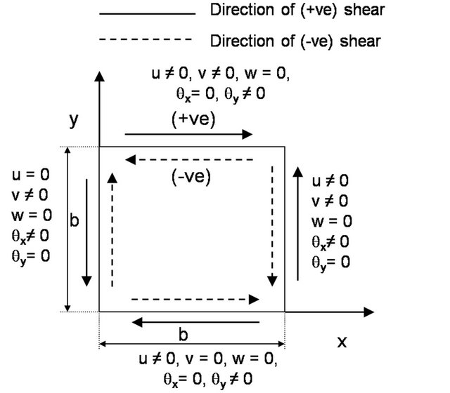
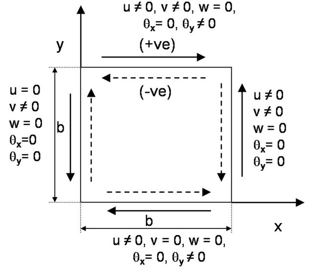
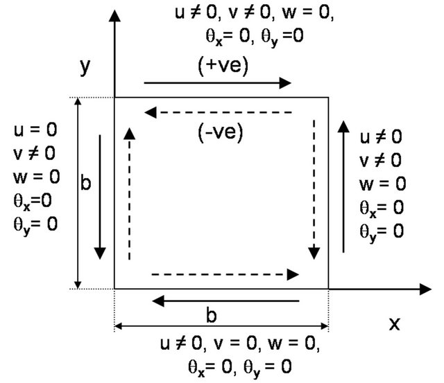
2.4. Boundary and Loading Conditions
Three different types of flexural edge boundary conditions, namely BC1, BC2 and BC3 (as shown in Figure 1) are considered; BC1 refers to a plate with all edges simply supported, BC2 refers to a plate with two longitudinal edges (y = 0 and y = b) simply supported and the
Table 1. Material Properties of T300/5208 (pre-peg) graphite-epoxy.

Table 2. Details of cutout shapes and their dimensions.
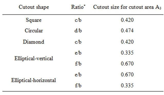
*Refer to Figures 3 and 4 for various notations.
BC1
(a)
BC2
(b)
BC3
(c)
Figure 1. Details of various boundary conditions: (a) BC1, (b) BC2, and (c) BC3; with the shear load directions.
other two edges clamped (i.e., x = 0 and x = b) and BC3 refers to a plate with all edges clamped. In all three cases, the in-plane boundary conditions on edges x = 0, x = b, y = 0 and y = b related to in-plane displacements in xand y-direction (i.e., u and v, respectively) are identical. In-plane uniformly distributed shear loads (positive and negative) are applied on all four edges of the laminate by taking equivalent nodal forces at boundary edge of each boundary element. The notations for positive and negative shear loads are also depicted in Figure 1.
Results for failure loads and the corresponding deflections are presented in the following non-dimensionalized forms:
In-plane shear load: 
Maximum transverse deflection: wmax/h Here, E2 is the transverse elastic modulus of a lamina; h is the thickness of the laminate; b is the width of the square plate; Nxy is the in-plane shear loads per unit width of the plate; and, wmax is the maximum transverse deflect tion.
2.5. Convergence Study
To fix the number of elements in the finite element mesh, a convergence study was conducted for a simply-supported quasi-isotropic laminate with a central square cutout of area A3 using 72, 96, 120, 144 and 168 elements. The convergence of buckling and first-ply failure loads was checked under positive shear load. Results of convergence study are shown in Table 3. From Table 3 it can be observed that buckling and first-ply failure loads do not show any variation after 144 numbers of elements and hence convergence is achieved for 144 elements. For the sake of uniformity, finite element mesh of 144 elements has been considered for the laminate with all shaped cutouts. In the case of laminate without cutout, the convergence of results has been obtained for finite element mesh of 5 × 5 and corroborate with the results obtained by Singh [20]. Schematic of finite element meshes along with elementand node-numbering schemes for a typical square laminate without cutout and with a circular
Table 3. Convergence study.

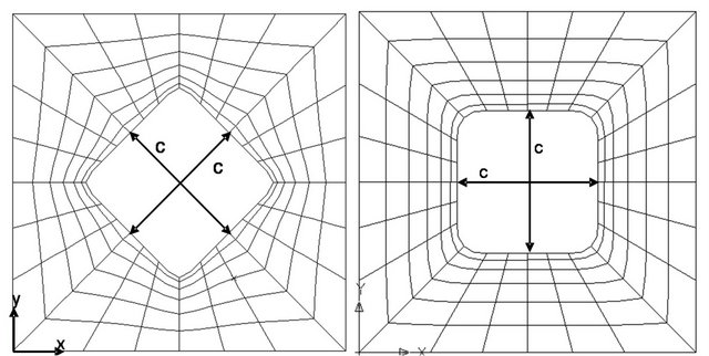
cutout are illustrated in Figures 2 and 3, respectively. Schematics of finite element mesh for square laminates with other cutout shapes are shown in Figure 4.
3. Verification of Results
The accuracy of the developed program under in-plane shear is checked by comparing results (buckling loads, postbuckling response and first-ply failure loads) with the numerical and/or experimental results published by Jha and Kumar [14], Guo [16] and Kosteletos [21]. Table 4 contains the details of comparison along with the validated results. The material properties used were the same as given in the respective references. From Table 4, a good agreement of the results from the developed program can be observed with the results presented by Jha and Kumar [14], Guo [16] and Kosteletos [21]. Further, the load-deflection response of (45/−45)2s laminate without cutout obtained in the present study matches with that of Kosteletos [21], as shown in Figure 5.
4. Results and Discussions
4.1. Effects of Cutout Shapes for Various Boundary Conditions
The effects of edge boundary conditions (BC1, BC2 and BC3) on load-deflection responses of the symmetric quasi-isotropic laminate, (+45/−45/0/90)2s without cutout are shown in Figure 6, for positive and negative shear loads. Figures 7(a)-(e) depict the load-deflection responses of the laminate with a cutout of various shapes
(i.e., circular, square, diamond, elliptical-vertical and elliptical-horizontal, respectively) for both directions of shear load. Points corresponding to first-ply failure and ultimate failure are also highlighted in Figures 6 and 7(a)-(e). Details of failure characteristics for the laminate without and with various shaped cutouts subjected to different boundary conditions are tabulated in Tables 5 and 6 for positive and negative shear loads, respectively. The buckling load of the laminate with a cutout of various shapes is less than that of the laminate without cutout, irrespective of edge boundary conditions and directions of

Figure 2. Meshing of a square laminate without cutout showing elementand node-numbering scheme.
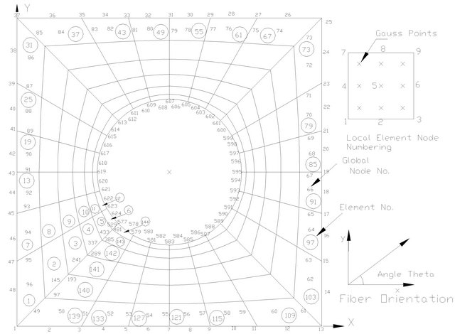
Figure 3. Finite element mesh showing elementand node-numbering scheme for a typical square laminate with circular cutout.
 (a)
(a)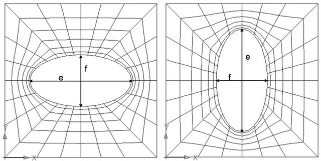 (b)
(b)
Figure 4. Meshing of square laminate with: (a) Diamond; (b) Square; (c) Elliptical-horizontal; and (d) Elliptical-vertical cutouts.

Figure 5. Comparison of load-deflection response of (45/ −45)2s laminate without cutout with Kosteletos [21] under positive and negative shear loads.
shear load. For positive shear load, the maximum and minimum reductions of buckling loads of the laminate with a cutout (except for the laminate with a diamond cutout under BC3 boundary condition) as compared to the laminate without cutout are observed to be for BC1 and BC3 boundary conditions, respectively, for all cutout shapes. Variations in buckling load with cutout shape are within 11.9%, 12.8% and 4.74% for boundary conditions BC1, BC2 and BC3, respectively, in the case of positive
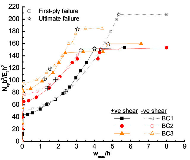
Figure 6. Effects of boundary conditions (BC1, BC2 and BC3) on load-deflection responses of quasi-isotropic laminate without cutout under positive and negative shear loads.
shear load. However, for negative shear load, there is no such definite prediction of change in buckling load of the laminate with a cutout as compared to the laminate without cutout for different boundary conditions. Also, under negative shear load, the variations in buckling load with cutout shape are within 15.8%, 16.4% and 21.4% for boundary conditions BC1, BC2 and BC3, respectively. So, it can be observed that the effect of cutout shapes on buckling load is more for BC2 and BC3 boundary conditions under positive and negative directions of shear load, respectively.
Further, for both directions of shear load and all cutout shapes other than diamond, the laminate with clamped boundary condition (BC3) has higher buckling load as compared to the laminate with other two types of boundary conditions (i.e., BC1 and BC2), as given in Tables 5 and 6. It is also to be noted from Figure 7(c) that the laminate with a diamond shape cutout under BC3 boundary condition shows no buckling failure for both directions of shear load because of early delamination of the laminate before buckling.
As given in Tables 5 and 6, the first-ply failure load is also decreased by the introduction of cutout in the laminate for all boundary conditions and for both directions of shear load. Except the laminate with a circular cutout under positive shear and the laminate with an ellipticalvertical cutout under negative shear, the maximum reduction of first-ply failure loads due to cutout of various shapes as compared to the laminate without cutout is found to be for BC3 boundary condition for both shear load directions. The maximum reduction of first-ply Failure load is found to be for the laminate with a diamond cutout with BC3 boundary condition, for positive as well as negative shear load, wherein the early delamination
Table 4. Verification of results.

aFirst-ply failure results are based on Tsai-Hill failure criterion. bThe quantities inside and outside parentheses represent the critical buckling load (kN) from the FE analysis and experimental investigation, respectively. cKosteletos’s results presented here are extracted from the figure given in the paper.
Table 5. Details of failure characteristics of quasi-isotropic laminate with and without various shaped cutouts for boundary conditions BC1, BC2 and BC3 under positive shear load.
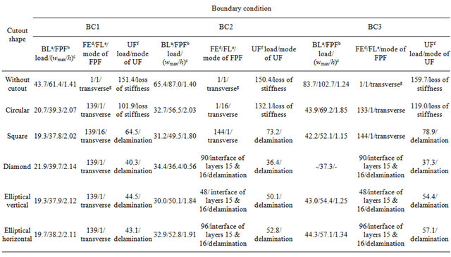
aBuckling load; bFirst-ply failure; cNon-dimensionalized maximum transverse deflection at the first-ply failure; dFirst failed element number; eFirst failed layer number/interface of the first failed element; fUltimate failure; gTransverse mode of failure refers to the failure of lamina in a direction perpendicular to the fiber direction due to in-plane stresses transverse to fiber direction.
 (a)
(a)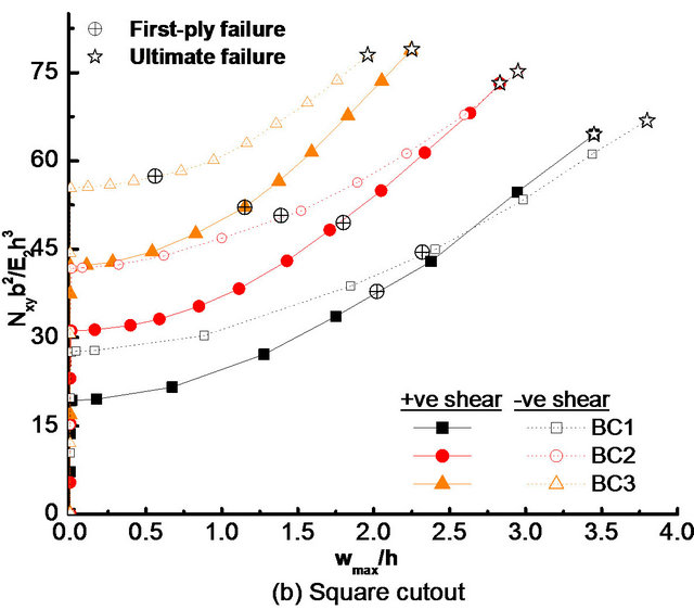 (b)
(b)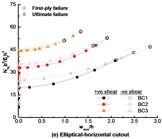 (c)
(c)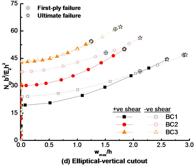 (d)
(d)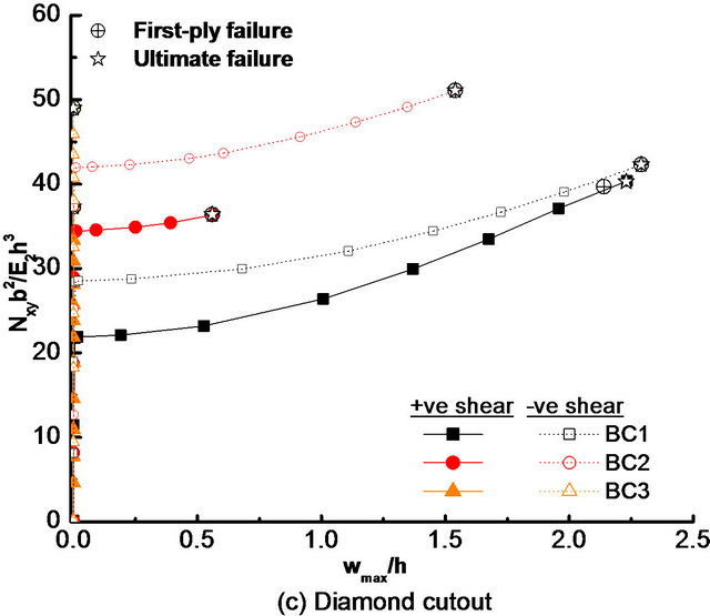 (e)
(e)
Figure 7. Effects of boundary conditions (BC1, BC2 and BC3) on load-deflection response of quasi-isotropic laminate with: (a) Circular; (b) Square; (c) Diamond; (d) Elliptical-vertical; and (e) Elliptical-horizontal cutouts, under positive and negative shear loads.
Table 6. Details of failure characteristics of quasi-isotropic laminate with and without various shaped cutouts for boundary conditions BC1, BC2 and BC3 under negative shear load.
aBuckling load; bFirst-ply failure; cNon-dimensionalized maximum transverse deflection at the first-ply failure; dFirst failed element number; eFirst failed layer number/interface of the first failed element; fUltimate failure; gTransverse mode of failure refers to the failure of lamina in a direction perpendicular to the fiber direction due to in-plane stresses transverse to fiber direction.
takes place to cause ultimate failure before buckling. It is important to note from Table 5 that under positive shear load, the effect of cutout shape on first-ply failure load is the least for the laminate with BC1 boundary condition (maximum variation within 4.79%) and it becomes most (maximum variation within 46.1%) for BC3 boundary condition. For negative shear load, the effect of cutout shape on first-ply failure load is almost uniform for all boundary conditions (maximum variation within 25.6%).
As shown in Tables 5 and 6, irrespective of boundary conditions and loading directions, the modes of first-ply failure for the laminate with and without square and circular cutouts remain the transverse mode (i.e., matrix failure due to stress transverse to fiber direction). However, the first-ply failure is caused by delamination in the case of laminate with diamond and elliptical-horizontal cutouts with boundary conditions BC2 and BC3, for both directions of shear load. Variation in first-ply failure mode with the change in shear load direction (from positive to negative) can also be observed from matrix failure to delamination and vice-versa, respectively, for the laminate with diamond and elliptical-horizontal cutouts under BC1 boundary condition, and for the laminate with an elliptical-vertical cutout under BC2 and BC3 boundary conditions. The first-ply failure occurs at the outer edge of the laminate in the case of the laminate without cutout for all boundary conditions and for both directions of shear load. Under positive shear load, the location of the first-ply failure remains at outer edge of the laminate for all shaped cutouts for boundary condition BC1, whereas for other boundary conditions (i.e., BC2 and BC3), the first-ply failure takes place near the cutout edge for the laminate with a non-circular cutout. However, in the case of the laminate with circular cutout, it remains at outer edge of the laminate. It is important to note from Table 6 that under negative shear load, the critical location for the first-ply failure is at cutout edge only for almost all boundary conditions and all shaped cutouts.
From Tables 5 and 6, it can be noted that ultimate failure load also gets reduced with the introduction of a central cutout in the laminate. Maximum reduction in ultimate failure load, as compared to the laminate without cutout, is observed for the laminate with a diamond shaped cutout and minimum reduction is found to be for the laminate with a circular cutout. This observation is true for almost all boundary conditions and for both directions of shear load. It is also important to note that for positive as well as negative shear load, the effect of cutout shape on ultimate failure load is significant for all boundary conditions. This is based on the fact that the laminate with a circular cutout bears maximum ultimate failure load, because the complete loss of stiffness is the cause of ultimate failure in this laminate; whereas in the case of laminate with other shaped cutouts, the ultimate failure load goes to minimum due to early delamination. It is to be pointed out that the material strength is utilized efficiently in the case of laminate with a circular cutout because delamination in the laminate with a circular cutout occurs when the laminate has virtually no reserve strength due to complete loss of stiffness. It is to be noted that for boundary condition BC1, the effect of cutout shape on ultimate failure load is same (maximum within 60.1%) for positive and negative directions of shear load, whereas for boundary conditions BC2 and BC3, this effect is more (maximum within 72.2% for BC2) for positive shear load than negative shear load (maximum within 63.4% for BC3).
It may be noted from Figures 7(a)-(e) that except the values of failure loads (i.e., first-ply failure and ultimate failure loads), the postbuckling response of the laminate with a cutout in terms of stiffness (given by the slope at a point in postbuckling range) at a particular value of maximum deflection is almost the same for boundary conditions BC1, BC2 and BC3 irrespective of cutout shapes and directions of shear load. So, it can be concluded that there is no much effect of boundary conditions on postbuckling stiffness of the laminate with a cutout. It can also be observed from Figures 7(a)-(e) that except in the case of laminate with an elliptical (vertical and horizontal) cutout under BC3 boundary condition, although the quasi-isotropic laminate with a cutout has more postbuckling strengths under negative shear load than that under positive shear load in the early range of postbuckling for various boundary conditions, but in the advance stage of postbuckling response, strengths of the laminate become larger under positive shear load than that under negative shear load and hence, it can be argued that the laminate has more postbuckling stiffness under positive shear load than that under negative shear load. In the case of laminate with an elliptical (vertical and horizontal) cutout under BC3 boundary condition, the load-deflection curves for positive and negative shear loads (i.e., postbuckling responses) almost overlap each other and hence, there is no effect of shear load directions on postbuckling stiffness. In addition, it is also important to mention that the effects of boundary condition on buckling, first-ply failure and ultimate failure loads (given by maximum percentage change in buckling, first-ply failure and ultimate failure loads with change in boundary condition) of the quasi-isotropic laminate with a cutout is more for positive shear load than that for the negative shear load for almost all cutout shapes.
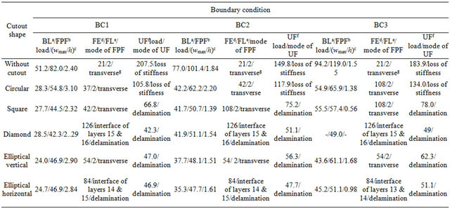
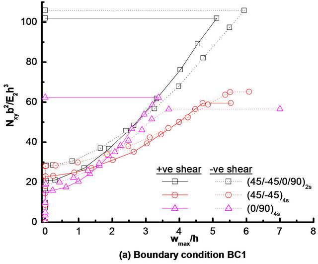
4.2. Effects of Composite Lay-Ups for Various Boundary Conditions
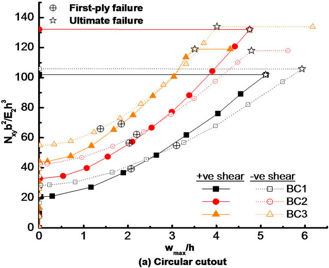
The effects of composite lay-ups on load-deflection responses of square laminate with a typical central circular cutout under positive and negative shear loads is shown in Figures 8(a)-(c), respectively, for boundary conditions BC1, BC2 and BC3. Three most practical laminate configurations (i.e., quasi-isotropic [i.e., (+45/−45/0/90)2s], angle-ply [i.e., (45/−45)4s], and cross-ply [i.e., (0/90)4s])
 (a)
(a)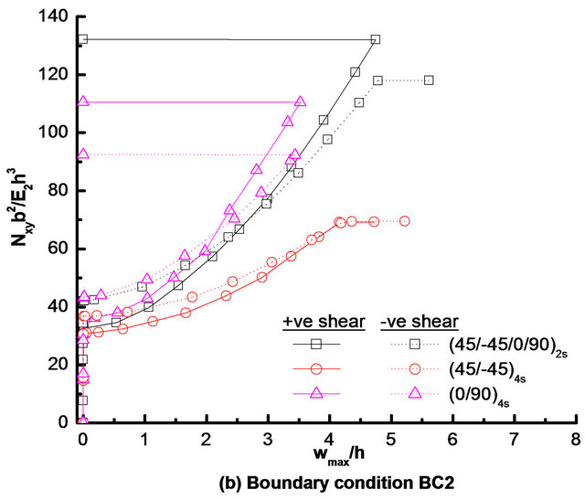 (b)
(b)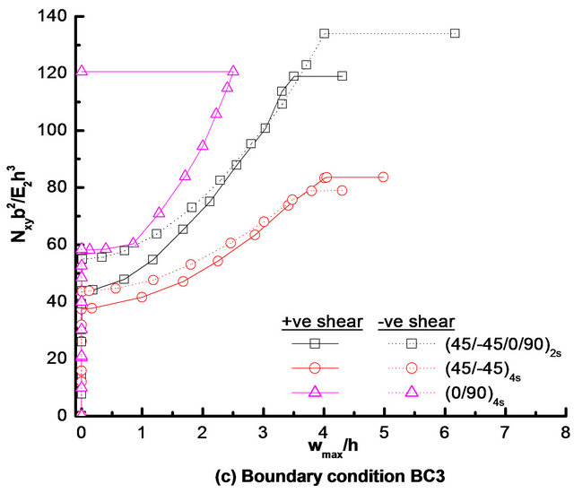 (c)
(c)
Figure 8. Effect of composite lay-ups on load-deflection response of square laminate with a typical circular cutout under positive and negative shear loads, subjected to boundary conditions: (a) BC1; (b) BC2; and (c) BC3.
are considered for this study. Corresponding details of failure characteristics for these laminates under positive and negative directions of shear loads and boundary conditions BC1, BC2 and BC3 are given in Table 7. It can be noted from Table 7 that for BC1, angle-ply [i.e., (45/−45)4s] and cross-ply [i.e., (0/90)4s] laminates have maximum and minimum buckling strengths, respectively, for both directions of shear load. However, for other two boundary conditions (i.e., BC2 and BC3), cross-ply and angle-ply laminates have maximum and minimum buckling strengths, respectively, for positive as well as negative shear load. It is also to be observed that for BC3 boundary condition, the onset of buckling is precluded for (0/90)4s laminate under negative shear load since the first-ply failure and subsequently the ultimate failure (due to complete loss of stiffness) because of the successive failures at the same load occur before buckling. Irrespective of shear directions and boundary conditions, (+45/−45/0/90)2s laminate has the maximum first-ply failure load, whereas the (45/−45)4s laminate has minimum first-ply failure load. From Table 7, it is also to notice that almost all laminate configurations have more buckling and first-ply failure loads under negative shear load than that under positive shear load, irrespective of boundary conditions.
As presented in Table 7 that except for (0/90)4s laminate with boundary condition BC1 under negative shear load, the mode of first-ply failure for all laminate configurations remains matrix failure (i.e., transverse mode of failure) under positive as well as negative shear load for all boundary conditions under considerations. In the case of (0/90)4s laminate with boundary condition BC1 under negative shear load, the first-ply failure is caused by inplane shear stress. It is to be noted that for all boundary conditions, the first-ply failure initiates at cutout edge and outer edge of the laminate, respectively, for (45/− 45)4s and (0/90)4s lay-ups under positive as well as negative shear load. In the case of quasi-isotropic laminate, for boundary conditions BC2 and BC3, the critical location for first-ply failure changes from outer edge of the laminate to cutout edge as the direction of shear load changes from positive to negative, whereas for BC1 boundary condition, the first-ply failure occurs only at outer edge of the laminate for both directions of shear load. The ultimate failure of laminate with a central circular cutout and having lamination sequences (+45/−45 /0/90)2s, (45/−45)4s and (0/90)4s, is caused by the complete loss of stiffness due to large transverse deflection, irrespective of boundary conditions and directions of shear load. As presented in Table 7, for almost all boundary conditions and for both directions of shear loadthe quasi-isotropic laminate is found to have maximum ultimate failure load.
Table 7. Detail of failure characteristics of (+45/−45/0/90)2s, (45/−45)4s and (0/90)4s laminates with a typical circular cutout under positive and negative shear loads for boundary conditions BC1, BC2 and BC3.

aBuckling load; bFirst-ply failure; cNon-dimensionalized maximum transverse deflection at the first-ply failure; dFirst failed element number; eFirst failed layer number/interface of the first failed element; fUltimate failure; gTransverse mode of failure refers to the failure of lamina in a direction perpendicular to the fiber direction due to in-plane stresses transverse to fiber direction.
It is also worth mentioning that as in the case of quasiisotropic laminate with various shaped cutout, the effects of boundary condition on buckling, first-ply failure and ultimate failure loads for the angle-ply and cross-ply laminates with a circular cutout is maximum for positive shear load than the negative shear load. Furthermore, it is noted that for both directions of shear load, the maximum effects of boundary condition on buckling and failure loads is for cross-ply laminate, whereas the minimum effects is observed for angle-ply laminate. Moreover, it is also important to note from Figures 8(a)-(c), the postbuckling stiffness (given by the slope of load versus deflection curve at a particular value of maximum transverse deflection) of (0/90)4s laminate is maximum, whereas it is minimum for (45/−45)4s laminate, irrespective of boundary conditions and directions of shear load.
5. Concluding Remarks
Based on the aforementioned results and discussion, the following important observations can be made:
• The effect of cutout shapes on buckling load of quasi-isotropic laminate is more for BC2 and BC3 boundary conditions, respectively, under positive and negative directions of shear load.
• The effect of boundary conditions on postbuckling stiffness is not appreciable for quasi-isotropic laminate with a cutout of various shapes.
• For boundary condition BC1, angle-ply [i.e., (45/ −45)4s] and cross-ply [i.e., (0/90)4s] laminates have maximum and minimum buckling strengths, respectively, for both directions of shear load. However, for other two boundary conditions, reverse is true for positive as well as negative shear load.
• All laminate configurations have more buckling and first-ply failure loads under negative shear load than that under positive shear load, irrespective of boundary condition.
• Matrix failure due to transverse stresses is the predominant mode of first-ply failure for various laminate configurations under positive as well as negative shear load for all boundary conditions.
• Irrespective of shear directions and boundary conditions, the quasi-isotropic laminate has the maximum first-ply failure and ultimate failure loads as compared to the angle-ply and cross-ply laminates.
• Irrespective of laminate configurations, the laminate with a circular cutout has more effects of boundary conditions on buckling, first-ply failure and ultimate failure loads under positive shear load than that under the negative shear load; the maximum and minimum effects being for the cross-ply and the angle-ply laminates, respectively.
• Quasi-isotropic laminate with a circular cutout has more postbuckling stiffness under positive shear load than the laminate under negative shear load, irrespective of boundary condition; and the cross-ply and angle-ply laminates have maximum and minimum postbuckling stiffness, respectively.
REFERENCES
- R. M. Jones, “Mechanics of Composite Materials,” McGrawHill, Kogakusha Ltd., Tokyo, 1975.
- S. B. Singh and D. Kumar, “Postbuckling Response and Failure of Symmetric Laminated Plates with Rectangular Cutouts under Uniaxial Compression,” Structural Engineering and Mechanics, Vol. 29, No. 4, 2008, pp. 455- 467.
- T. Özden, “Analysis of Critical Buckling Load of Laminated Composites Plate with Different Boundary Conditions Using FEM and Analytical Methods,” Computational Materials Science, Vol. 45, No. 4, 2009, pp. 1006- 1015. doi:10.1016/j.commatsci.2009.01.003
- S. K. Panda and L. S. Ramachandra, “Buckling of Rectangular Plates with Various Boundary Conditions Loaded by Non-Uniform In-Plane Loads,” International Journal of Mechanical Sciences, Vol. 52, No. 6, 2010, pp. 819-828. doi:10.1016/j.ijmecsci.2010.01.009
- D. Kumar and S. B. Singh, “Effects of Boundary Conditions on Buckling and Postbuckling Responses of Composite Laminate with Various Shaped Cutouts,” Composite Structures, Vol. 92, No. 3, 2010, pp. 769-779. doi:10.1016/j.compstruct.2009.08.049
- S. B. Singh and D. Kumar, “Postbuckling Response and Failure of Symmetric Laminated Plates with Rectangular Cutouts under In-Plane Shear,” Structural Engineering and Mechanics, Vol. 34, No. 2, 2010, pp. 175-188.
- Y. Zhang and F. L. Matthews, “Postbuckling Behaviour of Anisotropic Laminated Plates under Pure Shear and Shear Combined with Compressive Loading,” Journal of American Institute of Aeronautics and Astronautics, Vol. 22, No. 2, 1984, pp. 281-286.
- S. B. Singh and A. Kumar, “Postbuckling Response and Failure of Symmetric Laminates under In-Plane Shear,” Composite Science and Technology, Vol. 58, No. 12, 1998, pp. 1949-1960. doi:10.1016/S0266-3538(98)00032-3
- M. P. Nemeth, “Buckling and Postbuckling Behavior of Laminated Composite Plates with a Cutout,” 1996.
- V. O. Britt, “Shear and Compression Buckling Analysis for Anisotropic Panels with Elliptical Cutouts,” Journal of American Institute of Aeronautics and Astronautics, Vol. 32, No. 11, 1994, pp. 2293-2299.
- R. J. Herman, “Postbuckling Behavior of Graphite/Epoxy Cloth Shear Panels with 45˚-Flanged Lightening Holes,” M.S. Thesis, Naval Postgraduate School, Monterey, 1982.
- G. J. Turvey and K. Sadeghipour, “Shear Buckling of Anisotropic Fibre-Reinforced Rectangular Plates with Central Circular Cutouts,” Proceedings of the International Conference Computer Aided Design in Composite Material Technology, Southampton, 1988, pp. 459-473.
- S. Vellaichamy, B. G. Prakash and S. Brun, “Optimum Design of Cutouts in Laminated Composite Structures,” Computers & Structures, Vol. 37, No. 3, 1990, pp. 241- 246. doi:10.1016/0045-7949(90)90315-S
- P. N. Jha and A. Kumar, “Response and Failure of Square Laminates under Combined Loads,” Composite Structures, Vol. 55, No. 3, 2002, pp. 337-345. doi:10.1016/S0263-8223(01)00141-6
- P. Jain and A. Kumar, “Postbuckling Response of Square Laminates with a Central Circular/Elliptical Cutout,” Composite Structures, Vol. 65, No. 2, 2004, pp. 179-185. doi:10.1016/j.compstruct.2003.10.014
- S. J. Guo, “Stress Concentration and Buckling Behaviour of Shear Loaded Composite Panels with Reinforced Cutouts,” Composite Structures, Vol. 80, No. 1, 2007, pp. 1-9. doi:10.1016/j.compstruct.2006.02.034
- S. Guo, R. Morishima, X. Zhang and A. Mills, “Cutout Shape and Reinforcement Design for Composite C-Section Beams under Shear Load,” Composite Structures, Vol. 88, No. 2, 2009, pp. 179-187. doi:10.1016/j.compstruct.2008.03.001
- D. Kumar and S. B. Singh, “Postbuckling Strengths of Composite Laminate with Various Shaped Cutouts under InPlane Shear,” Composite Structures, Vol. 92, No. 12, 2010, pp. 2966-2978. doi:10.1016/j.compstruct.2010.05.008
- O. O. Ochoa and J. N. Reddy, “Finite Elements Analysis of Composite Laminates,” Kluwer Academic Publishers, Dordrecht, 1992.
- S. B. Singh, “Postbuckling Response, Strength and Failure of Symmetric Laminates,” Ph.D. Dissertation, Indian Institute of Technology, Kanpur, 1996.
- S. Kosteletos, “Postbuckling Response of Laminated Plates under Shear Loads,” Composite Structures, Vol. 20, No. 3, 1992, pp. 137-145. doi:10.1016/0263-8223(92)90020-D
- Z. Hashin, “Failure Criteria for Unidirectional Fiber Composites,” Journal of Applied Mechanics, Vol. 47, No. 3, 1980, pp. 329-334. doi:10.1115/1.3153664
- S. W. Tsai, “A Survey of Macroscopic Failure Criteria for Composite Materials,” Journal of Reinforced Plastics and Composites, Vol. 3, No. 1, 1984, pp. 40-62. doi:10.1177/073168448400300102
Appendix
(1) Tsai-Hill Criterion
In this criterion a considerable interaction exists among failure strengths of the lamina as against the other noninteractive criteria such as Hashin [22] and Tsai’s [23] tensor polynomial criteria. Tensor polynomial form of the Tsai-Hill criterion can be obtained from the following most general polynomial failure criterion of Tsai [23] at failure state.
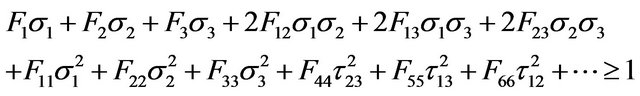
wherein, Fi, Fij are the strength tensors of the second and fourth rank;  are the normal stress components in principal material directions 1, 2 and 3, respectively (the subscript 1 referring to the fiber direction);
  are the shear stress components in the planes 1 - 2, 1 - 3 and 2 - 3, respectively. In Tsai-Hill criterion the following strength tensors are used in the above expression.
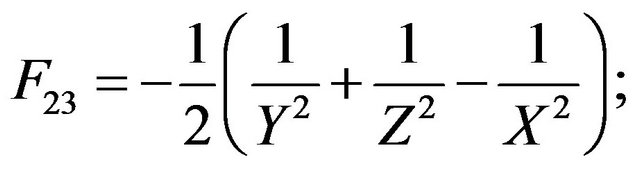
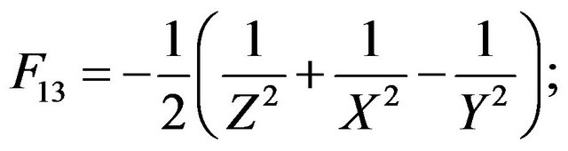

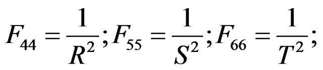
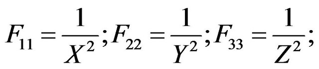
In the above expressions X, Y and Z are the normal strengths (tensile or compressive, depending upon the sign of ) along principal material directions 1, 2 and 3, respectively; R, S and T are the shear strengths of lamina in planes 2 - 3, 1 - 3 and 1 - 2, respectively
(2) Interlaminar Failure Friterion
As per the interlaminar failure criterion, the onset of delamination takes place when the interlaminar transverse stress (calculated by integration of equilibrium equations) components satisfy the following expression:
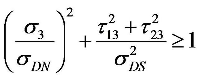
where,  is the transverse normal stress component;
  are the transverse shear stress components in principal material planes 1 - 3 and 2 - 3, respectively;
 ![]() is the peel strength and
is the peel strength and  is the interlaminar shear strength; these are taken equal to the tensile normal transverse strength and transverse shear strength (corresponding to the plane 1 - 3) of lamina, respectively.
NOTES
*Corresponding author.