New Journal of Glass and Ceramics
Vol.3 No.1(2013), Article ID:27342,13 pages DOI:10.4236/njgc.2013.31004
Mechanical Properties of Porosity-Free Beta Tricalcium Phosphate ((-TCP) Ceramic by Sharp and Spherical Indentations
![]()
1Laboratory of Mechanics of Lille, University of Lille, Lille, France; 2Laboratory of Materials and Process, University of Valenciennes and Hainaut Cambraisy, Valenciennes, France.
Email: didier.chicot@univ-lille1.fr
Received September 26th, 2012; revised October 26th, 2012; accepted November 5th, 2012
Keywords: β-TCP Ceramic; Indentation; Bulk Modulus; Hardness; Tensile Properties
ABSTRACT
Instrumented indentation has been developed for determining the mechanical properties of materials but an accurate determination of these properties requires attention on contact stiffness analysis, indentation size effect, elastic modulus mode of calculation, role of stress distribution around the indent and its introduction in expanding cavity models for tensile mechanical properties determination. In the present work, models for hardness, elastic modulus and plastic properties determination by indentation are briefly reviewed and applied for the characterization of a porosity-free β-TCP bioceramic. As a main result the elastic modulus is found to be equal to 162 GPa resulting from the application of different approaches based on the use of various sharp and spherical indenters. Additionally, Martens and contact macrohardnesses were found to be independent on the dwell-time and equals to 4.1 and 6.3 GPa, respectively. Finally, models based on Hollomon’s and Ludwik’s laws as well as expanding cavity models were critically analyzed in light of their capacity to determine the yield stress and to represent the behavior law of the material. As a main result, the yield stress of the β-TCP is found to be equal to 2 GPa.
1. Introduction
Among the experimental techniques used for the determination of mechanical properties of ceramics, the instrumented indentation test (IIT) is probably the most useful since it allows collecting information on hardness, elastic modulus and tensile properties from a single load-depth indentation curve. However, due to the variety of indentation conditions, different methodologies and, subsequently, different models can be applied for characterizing the mechanical behavior of a material. For example, some models consider the indentation size effect modeled by Nix and Gao [1] into the hardness calculation [2] or in the expanding cavity models for tensile properties determination [3] while other models consider the hardness independently on the load [4,5]. To improve the accuracy on the determination of the elastic modulus from unloading curves, different correction factors proposed by Hay et al. [7], Antunes et al. [8] and FischerCripps [9] have been introduced into the model of Oliver and Pharr [6] to take into account the geometry of the indenter and the approximation made when applying the contact theory of Hertz. Still, an important question remains that divides the opinions of the researchers into two groups; one group considering that it is the Young’s modulus that is determined by IIT and another group stating that only the bulk modulus can be determined by this method. In our opinion, a part of the explanation is undoubtedly related to the standard calibration that is used for the determination of the elastic modulus. A first point is that the calibration used by the users of indentation equipments is based on the assumption that it is the Young’s modulus that is obtained from the standard procedure. A second point is that the procedure supposes a constant compliance of the system. As a matter of fact, we showed recently by molecular dynamic analysis that the bulk modulus is obtained by indentation instead of the Young’s modulus [10]. Moreover, in the same paper we showed that the compliance of the system depends on the indentation conditions in accordance to the observations of Fischer-Cripps [9] on the effect of nature, geometry, mounting of the sample on the total compliance of the system. As a consequence, the procedure should be to calculate the compliance for each test and to consider that is the bulk modulus which is determined by indentation.
The shape of the indenter is also of main influence on the estimated mechanical properties of a material. Some authors have compared spherical and sharp indentations. For example, Alcala et al. [5] studied the plastic deformation around spherical and Vickers indents in metals and ceramics. Gao [3] developed the expanding cavity models for spherical and conical indentations taking into account the indentation size effect. On the other hand, Chudoba et al. [11] suggest calculating the bulk modulus of a thin film using a spherical indenter instead of a conical one since it allows remaining the material completely elastic if the indenter radius is large enough and the load is low enough.
In the present paper, the first objective is to determine, as precisely as possible, the hardness, the elastic properties and the behavior law of a porosity-free beta tricalcium phosphate (b-TCP) bioceramic. The conditions in which the material is obtained are new and no data are available in literature concerning its mechanical properties. In addition, the dimensions of the sample that can be produced impede direct determination of the mechanical properties by standard mechanical tests. The second objective is to examine the validity of the interpretation of indentation results obtained by various indentation process and indenters (Knoop, Vickers and sphere). For the determination of the elastic modulus, Knoop indentation will be used within the objective to apply the Marshall’s method [12] based on the elastic recovery of the indent. Then Vickers and spherical indenters will be used to determine the elastic modulus in the conditions of calibration stated above. Concerning hardness determination, we will use classical methodologies combined with a loading curve modeling developed in [2]. Standard mechanical properties like flow stress or work-hardening coefficient must be known for useful comparison between industrial materials or to be included in numerical models. When application of tensile test is not possible for determining the tensile parameters, indentation can be used by means of application of models. In the present work, we will apply and discuss several of these models in order to determine the elasto-plastic properties of the b-TCP.
2. Materials and Experiments
2.1. Material
β-tricalcium phosphate powder was synthesized by coprecipitation of a mixture of diammonium phosphate solution NH4(HPO4)2 (Carlo Erba, France) and a calcium nitrate solution Ca(NO3)2, 4H2O (Brenntag, France) using aqueous precipitation technique. A Ca/P = 1.52 ratio was chosen in order to obtain stoichiometric powders [13]. The pH solution was maintained constant at 6.4 during the reaction by continuous ammonia addition. The temperature was fixed at 30˚C and maturation was carried out during 24 h. After ripening, the solution was filtered and the precipitate dried at 80˚C. Due to a significant specific surface area of the powder (>60 m2·g−1), the precipitate was calcined at high temperature to increase the average primary particle size. Afterwards, β-TCP was crushed in order to break agglomerates formed during calcination and to reduce the powder to its final particle size. This crushing was carried out by ball milling using HDPE milling jars and yttrium stabilized zirconia balls for a duration of 5 h. β-TCP slurries with powder concentration of 65 wt% were prepared with distilled water. The slurry dispersion was ensured by the addition of 1.5 wt% of the TCP content of a commercial organic dispersant (Darvan C, R.t. Vanderbilt. Co.) and ball milling during 1 h. Cylindrical shape specimens (20 mm diameter; 5 mm height) were obtained by slip casting. After drying, the specimens were sintered for a duration of 2 h by natural sintering. Calcination and sintering temperatures were selected at 750˚C and 1060˚C, respectively, in order to obtain less than 2% of porosity estimated by the Archimedes’ method. After sintering, the sample was heat-treated by a post-HIP treatment at 1050˚C under 150 MPa in Ar/O2 atmosphere to obtain a 100% dense material showing a semi-transparent aspect (Figure 1).
2.2. Indentation Experiments
Instrumented indentation experiments were performed with a micro-hardness Tester CSM 2-107 equipped with Vickers and spherical indenters using loads chosen in the range 0.2 to 10 N. Three tests are performed at each maximum applied load in order to evaluate the reproducibility of the experiments. Loading and unloading rates (expressed in mN/min) were set up at twice the value of the maximum applied load according to the
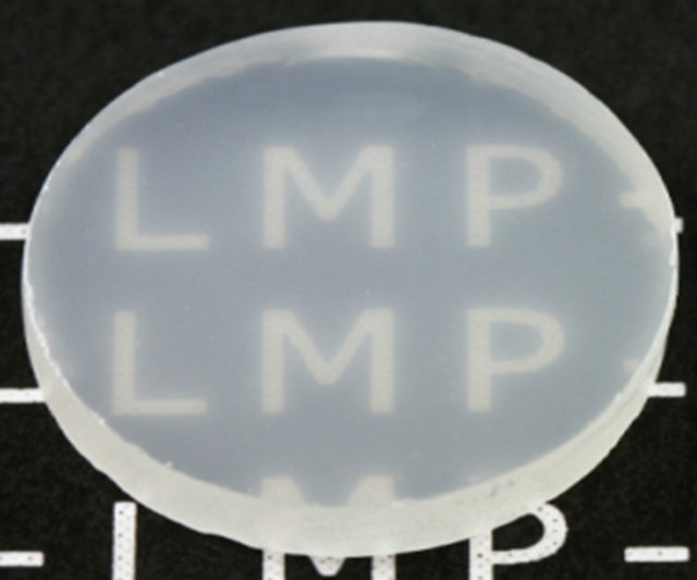
Figure 1. The dense b-TCP ceramic.
stant duration of one minute for the test. In addition, a recommendations of Quinn et al. [14] to ensure a condwell-time of 15 s was imposed according to the standard CSM test procedure. Knoop indentation tests were performed using a standard micro-indenter with a load of 5 N and a dwell-time of 15 s. All indentation experiments were performed on the flat side of the cylindrical sample.
3. Background Theory
3.1. Elastic Modulus
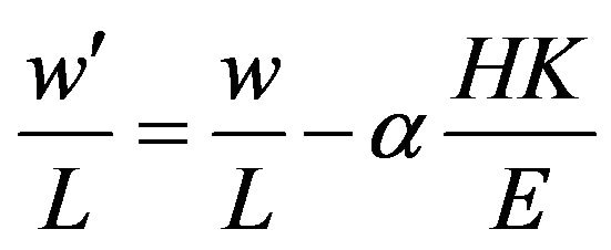
In 1980, Marshall et al. [12] suggested to evaluate the elastic modulus of a material by considering the elastic recovery of a Knoop indentation. These authors had observed that the small diagonal, w', of the indent was shorter than the expected theoretical value, w, while the large diagonal, L, remains constant after the withdrawal of the indenter. According to this observation, the authors proposed the following equation:
 (1)
(1)
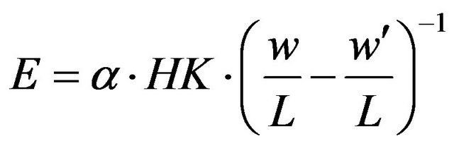
which allows the calculation of E by:
 (2)
(2)
Note that a = 0.45 when HK is calculated using the projected contact area of the indent [12] whereas a = 0.5 when considering the true contact area [15]. This method is simple but very imprecise when applied to material with predominant plastic behavior and should be restricted to hard predominantly elastic materials analysis.
Based on the original work of Doerner and Nix [16], Oliver and Pharr [6] proposed the calculation of the elastic modulus of a material from the determination of the compliance of the specimen and that of the instrument based on the analysis of the unloading part of a load (P)- depth (h) indentation curve. They proposed the following relation since the specimen compliance is given by the inverse of the contact stiffness, (dh/dP), calculated at the maximum indentation depth, hm:
 (3)
(3)
where AC is the projected contact area of the elastic contact measured from the indentation hardness impression. ER is the reduced modulus defined by:
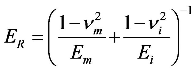 (4)
(4)
where Em, Ei, νm and νi represent the elastic modulus and the Poisson’s ratio of the material and the indenter, respectively.
Valid application of Equation (3) necessitates precise knowledge of AC and h. Moreover, these two parameters are not independent and a relation can be found between AC and h depending on the scale of indentation. For nanoindentation, the relation takes different forms [17] while, for microindentation which is the purpose of the work presented here, effects related to the imperfect sharpness of the tip are negligible. In this condition, the contact area can be represented by the simple expression:
 (5)
(5)
where  is the contact depth according to [6].
All the theoretical reasoning that was done until now supposes that the results are obtained using an infinite stiffness of the indentation system. In reality, this is not the case and the compliance of the system has to be taken into account. In fact, during the test, the displacement that is measured, hmeas is the result of the addition of the penetration of the indenter into the sample and the deformation of the indenting system: instrument frame, indenter, specimen mounting, etc. All these influences are taken into account in a correction proposed by Fischer-Cripps [9] under the form of a single parameter, Cf, named frame compliance. According to this author, the difference between hmeas and the actual indentation depth, h, is linearly proportional to the applied load. As a consequence, the indentation depth takes the following form:
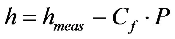 (6)
(6)
This expression shows the importance of knowing Cf as precisely as possible. Most of the time, researchers calibrate their system by performing indentations on fused silicate. By this way, they obtained a frame compliance Cf which is introduced and recognized as a constant in their analysis software. In reality this assumption is no true for higher loads. Indeed, in a previous work, we have confirmed the conclusions of Fischer-Cripps [9] about this coefficient, i.e. Cf is not a constant for a given apparatus but depends on range of loads, nature, size, shape, mounting and testing conditions of the sample [6,11].
Some other features are still to be considered for the application of Equation (3). Firstly, a coefficient β is needed to represent the geometry of the indenter when it is not a body of revolution. For a Vickers indenter, King [18] proposed a value of 1.012 whereas Dao et al. [19] proposed a value of 1.07. Using a three dimension simulation of the Vickers indentation, Antunes et al. [8] give 1.05 independently on the mechanical properties of the material which is the value here considered for b. Secondly, another coefficient, γ, has to be introduced to take into account the overestimation of the elastic modulus. This was shown by Hay et al. [7] whom pointed out that the assumptions considered in Sneddon’s solution did not lead to correct estimation of the radial displacements in the contact zone. These authors proposed the following relation to express γ which is only Poisson’s ratio dependent:
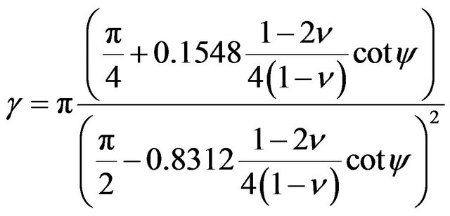 (7)
(7)
where y represents the half-angle of the equivalent conical indenter which would produce the same contact area of a pyramidal indenter under the same indentation load [20]. For a Vickers indenter y is equal to 70.3˚. n is the Poisson’s ratio of the tested material.
In a previous work [10], we proposed a modification of Equation (3) taking into account all these aspects for the calculation of the elastic modulus:
 (8)
(8)
This expression can be employed for every self-similar indenter like cone, Vickers or Berkovich indenters. In the particular case of spherical indenters, the deformation induced with different loads is not self-similar. The following considerations will explain how to take into account this problem. Hertz’s theory for sphere/plan contact provides three useful expressions. The relation between the maximum indentation depth, hm, and the contact indentation depth, hc:
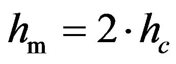 (9)
(9)
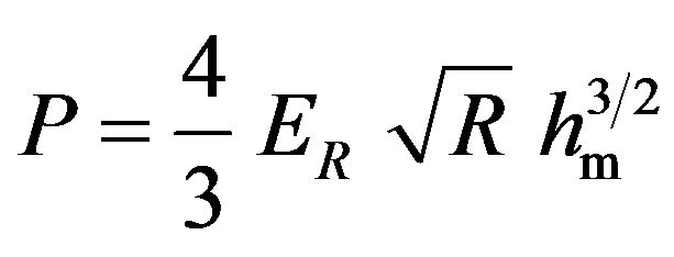
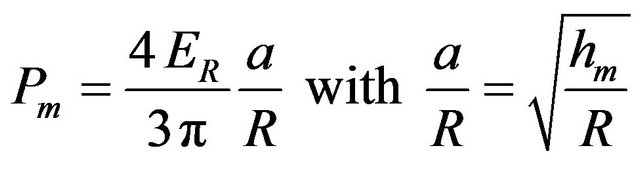
The relation between the applied load, P, and the contact radius, a:
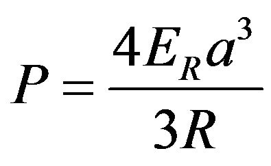 (10)
(10)
where ER is the reduced modulus and R the indenter radius.
The relation between the total displacement, hm, and the contact radius:
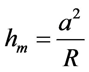 (11)
(11)
Using these three expressions, the objective is to represent the contact stiffness, (dh/dP), as a function of the contact depth, hc, and the reduced modulus. By combining Equation (10) and Equation (11), we may write:
 (12)
(12)
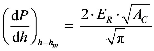
The derivation of the applied load compared to the maximum indentation depth leads to the following expression:
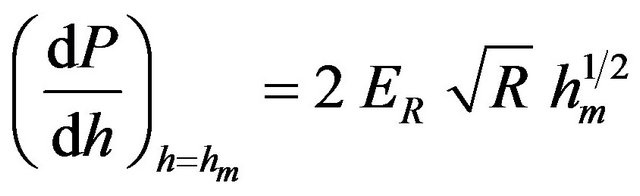 (13)
(13)
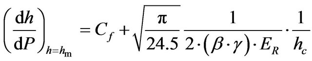
Taking into account Equation (9) and introducing in Equation (13) the frame compliance and the correction factors b and g, the contact stiffness for a spherical indenter can be expressed as a function of the square root of the reciprocal contact indentation depth, as follows:
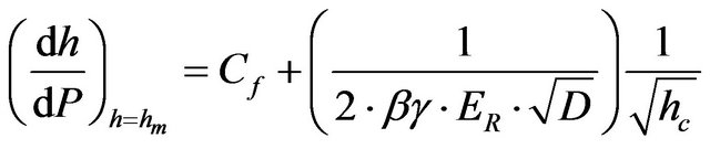 (14)
(14)
where β equals 1 and γ depends on Poisson's ratio and on the contact to indenter radii ratio [7]:
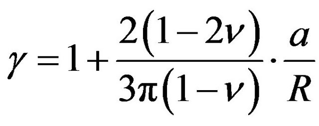 (15)
(15)
3.2. Hardness
The definition usually admitted for the hardness is the resistance of a material to plastic deformation induced by the penetration of a hard indenter. At the result of the indentation test, a remaining indent can be observed at the surface of the material as the manifestation of the extent of the plastic deformation. Measuring the dimensions of the indent allows calculating a hardness number using the following equation:
 (16)
(16)
where H is the hardness number, P the applied load and A, a representative area of the indent that can be the projected or the total contact area.
In instrumented indentation tests, the load-depth curve obtained during the test allows the calculation of a hardness number using the maximum distance (maximum indentation depth, hm, reached by the indenter during the indentation test), or the contact depth (indentation depth, hc, taking into account the deformation of the indent under load and calculated using the method of Oliver and Pharr [6]). As a consequence of all the possibilities to use one hardness number value or another, it is clear that comparison of the values that can be found in literature for a given material has to be carefully given for avoiding false conclusions about the hardness of this material. As an example it can be found in Table 1 the different possibilities to express the hardness of a material using a conical indenter.
Note that Martens hardness, HM, and contact hardness, HIT, are generally used for micro and nano-indentation, respectively. Another problem that has to be taken into account when dealing with hardness, whatever its definition, is that hardness number depends on the applied indentation load (Indentation Size Effect). This phenomenon has been associated to various causes such as work
Table 1. Hardness number calculations using total (true) or projected contact area and maximum or contact depth.

hardening, roughness, piling-up, sinking-in, shape of the indenter, surface energy, varying composition and crystal anisotropy, which have been all discussed extensively by Cheng and Cheng [21].
In a previous paper, Chicot et al. [22] have discussed the various relationships that have been produced in literature to represent this hardness-load dependence. To date, the strain gradient plasticity theory proposed by Nix and Gao [1] is probably the most applied. These authors proposed expressing the hardness as a function of the indentation depth as follows:
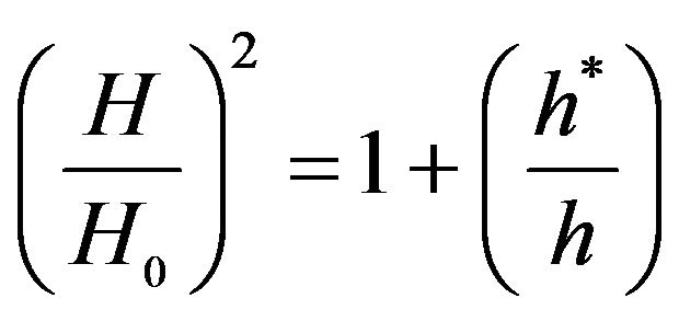 (17)
(17)
where H0 is the macrohardness and h* the characteristic scale-length.
Nix and Gao [1] assume for simplicity that the indentation deformation process is accommodated by geometrically necessary dislocations which are required to account for the permanent shape change at the surface. In these conditions, the macrohardness and the characteristic scale-length are:
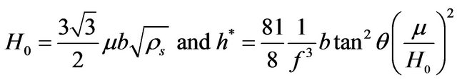 (18)
(18)
where µ is the shear modulus, b the Burger’s vector, rs the density of statistically stored dislocations and q is equal to 19.7˚. f is a corrective factor introduced afterwards by Durst et al. [23] to better represent the plastic zone size in nanoindentation. The factor f is equal to 1 in microindentation and, in nanoindentation, to 1.9 for Durst et al. [23] or 1.44 for Nix and Gao [1] who introduced the concept of non-uniformity of the dislocation spacing to explain this difference.
In practice, when applying relation (18) to nano or to micro indentation on the same material gives different results for H0 and h*. For this reason, Chicot [24] suggested an alternative approach to represent ISE whatever the indentation scale. In this work, a hardness lengthscale factor, HLSF, is defined:
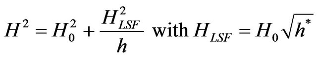 (19)
(19)
In order to use Equation (19), several indentation tests have to be performed on the same material. This is not always possible, especially in the case of heterogeneous material, where only one indentation can be performed on a local phase, constituent or particle.
Starting from the relation proposed by Zeng and Chiu [25] for the description of the loading curve:
 (20)
(20)
where P0 and C0 are fitting parameters, we proposed recently the following relation to take into account the indentation size effect [2]:
 (21)
(21)
This model allows representing the actual applied load (P) as a function of the actual indentation depth (h) involving the Martens macrohardness, HM0, the hardness length-scale factor, HMLSF, and a corrective load, P0.
3.3. Tensile Properties
In this part, some useful analytical models are going to be present in the objective of estimating tensile parameters from indentation tests. True-stress and true-strain, as determined by uniaxial tensile tests, were deduced from spherical indentation stress and strain through the following expressions [26]:
 (22)
(22)
 (23)
(23)
where pm is the mean pressure equivalent to the Meyer hardness calculated for spherical indentation, a is the contact radius and R the nominal radius of the indenter. Note that the ratio in Equation (22) varies between 2.8 and 3 for metals whereas it can vary between 2 and 4 for ceramic materials.
The mean pressure is calculated by:
 (24)
(24)
It is important to note that Equations (22) and (23) are applicable in the limit of a fully developed plastic contact, i.e. when a/R is close to 0.16 independently of the magnitude of the non-dimensional parameter sy/E and the Poisson’s ratio of the material. Moreover, in order to represent the plastic domain in tensile stress-strain deformation, different relations can be employed [27-29], the Hollomon’s law being probably the most used:
 (26)
(26)
where KH and nH are the strength coefficient and the strain-hardening exponent, respectively.
In order to be valid, the stress expressed in Equation (26) must be calculated considering the plastic strain. In practice when Hollomon’s law is not verified, Ludwik’s law is employed:
 (27)
(27)
where KL and nL are the strength coefficient and the strain-hardening exponent, corresponding to this law, respectively.
Equations (23), (25) and (26) can be combined [5]:
 (28)
(28)
An alternative expression was proposed by Matthews [4] in the special case of work-hardening materials:
 (29)
(29)
Based on Ludwik’s law, Huang et al. [30] suggested representing the mean pressure as the function of the flow stress, sflow, and to take into account the indentation size effect as follows:
 (30)
(30)
where  is assumed to represent the ISE in spherical indentation. The stress, sref, and the function, f(e), are deduced from Ludwik’s law as follows:
 (31)
(31)
Combining relations (23), (30) and (31), allows the expression of the applied load as a function of the indentation depth over the entire loading curve:
 (32)
(32)
Recently, Gao [3] proposed the introduction of strainhardening and indentation size effect in the expanding cavity models (ECMs) for conical and spherical indentation tests. This way the author was able to express the ratio between the mean pressure, pm, and the yield stress, sy, as a function of the contact radius to the indenter tip radius ratio, a/R. A series of relations were proposed according to the mechanical behavior of the tested material, ISE and the shape of the indenter.
For spherical indentation:
• Elastic perfectly plastic material with no strain gradient effect, (33)
• 
• Elastic perfectly plastic material with strain gradient effect, factor c, (34)
• 
• Elastic strain-hardening material with no strain gradient effect, (35)
• 
• Elastic strain-hardening material with strain gradient effect, factor c, (36)

For Vickers indentations where y is equal to 70.3˚:
• Elastic perfectly plastic material with no strain gradient effect, (37)
• 
• Elastic perfectly plastic material with strain gradient effect, (38)
• 
• Elastic strain-hardening material with no strain gradient effect, (39)
• 
• Elastic strain-hardening material with strain gradient effect, (40)

Note that relations (37) to (40) are similar to relation (20) where the second term corresponds to P0. We may then write Equation (41) instead of Equation (38):
 (41)
(41)
and Equation (42) instead of Equation (40):

Without any prior information on the mechanical behavior of the material, determination of the parameters of the tensile behavior law can be estimated by fitting the experimental data by these relations. This methodology allows determining yield stress, sy, strength coefficients, KH or KL, strain-hardening exponents, nH or nL, elastic modulus, E, and constants, c and  characterizing the indentation size effect.
4. Results and Discussion
In this part, we have applied the above-mentioned relations to the determination of elastic modulus, hardness and tensile properties.
4.1. Elastic Modulus
The elastic modulus of the dense b-TCP ceramic was calculated by applying indentation tests using Knoop, Vickers and spherical indenters.
4.1.1. Marshall’s Method Using Knoop Indenter [12]
Knoop indentations were performed using an indentation load of 5 N. In order to obtain accurate value for the elastic modulus, fifteen indents were performed under the same maximum applied load. As a result, the small diagonal length was found equal to 15.95 ± 0.25 µm and the large one to 124.8 ± 1.7 µm. An example of an indent is shown in Figure 2. Knoop hardness number HK, calculated with the projected contact area, was equal to 4.57 GPa and the elastic modulus was found to be equal to 160 ± 26 GPa by applying Equation (2).

Figure 2. Residual knoop indent obtained at Pmax = 5 N.
4.1.2. Instrumented Vickers Indentation
Instrumented indentation tests using a Vickers indenter were performed at the surface of the dense b-TCP ceramic by applying different maximum applied loads. As an example, Figure 3(a) shows selected typical loaddepth curves illustrating the good reproducibility of the loading. Analyzing the unloading part of the load-depth curves (Figure 3(a)), we represent the inverse of the contact stiffness as a function of the inverse of the indentation depth according to Equation (8) (Figure 3(b)).
The Poisson’s ratio of the b-TCP ceramic is equal to 0.22 for Kobayashi and Sakamoto [31] and for Yamadi and Kobayashi [32], 0.29 for Dantas et al. [33] or 0.3 for Shibata et al. [34]. In absence of any justification by these authors of its measurement, we retained the value of 0.3 for the Poisson’s ratio which leads to 1.067 for the calculation of the correction factor γ. The theoretical slope is then 0.1598/ER. As a consequence, the calculation gives 153 GPa for the reduced modulus ER which depends on the properties of indenter and material (Equation (4)). Considering 1140 GPa for the elastic modulus and 0.07 for the Poisson’s ratio for the diamond indenter [35], the elastic modulus of the dense b-TCP ceramic was found equal to 161 ± 5 GPa, a value very close to that obtained by the Marshall’s method.
4.1.3 Instrumented Spherical Indentation.
Instrumented indentation tests were performed using a spherical indenter with maximum loads ranging from 0.2 to 10 N. Figure 4 shows typical load-depth curves.
To apply the model for spherical indentations, Equation (9) between the maximum indentation depth and the contact indentation depth must be verified. As a matter of fact, Figure 5(a) shows that, for a major part of the experimental indentation data, the slope can be considered equal to 0.5 according to the theory while a significant
 (a)
(a) (b)
(b)
Figure 3. (a) Load-depth curves obtained with Pmax ranging between 0.01 and 5 N; (b) Inverse of the contact stiffness as a function of the inverse of the contact indentation depth According to Equation (8) resulting from Vickers indentation.

Figure 4. Load-depth curves obtained by spherical IIT with Pmax ranging from 0.2 N to 10 N.
 (a)
(a)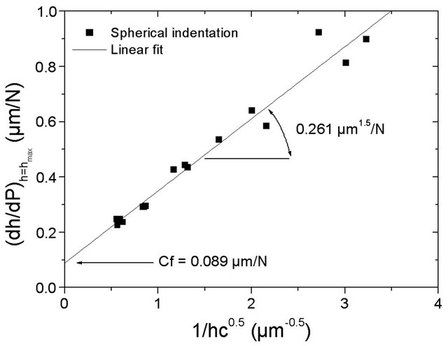 (b)
(b)
Figure 5. (a) Contact depth versus maximum depth; (b) Inverse of the contact stiffness versus the inverse of the square root of the contact depth according to Equation (14), both resulting from spherical indentation.
discrepancy occurs for the highest indentation depths. The corresponding data were not considered in the analysis. The selected points of Figure 5(a) are used in Figure 5(b) to represent the inverse of the contact stiffness as a function of the inverse of the square root of the reciprocal contact indentation depth. Since a linear variation is obtained, it is possible to neglect the correction factor g that appears in Equation (14). Considering the spherical indenter radius equals to 100 µm, a slope of 0.0354/ER is obtained and the reduced modulus equals to 135.6 GPa. Considering 540 GPa for the elastic modulus and 0.24 for the Poisson’s ratio of the tungsten carbide [36] of the ball indenter, a elastic modulus of 163 ± 10 GPa is found. Moreover, it was observed that cracking around the sharp indent occurs at different extent. No cracks were observed for spherical indentation whereas some small cracks appear along the long diagonals of the Knoop indentations and larger cracks at the tips of the Vickers indenter. It is remarkable that using three methodologies, three different indenters and three cracking modes lead to values that are very close together.
The average elastic modulus value of β-TCP obtained by the new process employed here which allows the fabrication of a porosity-free β-TCP is of 162 GPa which is 30 % higher than the value of single crystal β-TCP (120 GPa) reported by Viswanath et al. [37]. These authors wrote that to obtain higher value for the elastic modulus, the a-TCP phase has been eliminated by conversion of a-TCP into β-TCP by dissolution of a-TCP powder in the flux and recrystallisation of β-TCP single crystals. In addition, Viswanath et al. [37] added that the elastic modulus value of single crystal β-TCP is, at least, six times more that the elastic modulus of polycrystalline material reported by Wang et al. [38] or Metsger et al. [39]. For Viswanath et al. [37], the large difference obtained between single crystal and polycrystalline material is attributed to the defect-free nature of the miniature single crystal which can also explained the result obtained in the present work.
4.2. Hardness
Here, we are going to examine the conditions of calculation for the determination of Martens hardness, HM, and contact hardness, HIT. A particular attention will be focused on the choice of the moment of the measurement, i.e. at the onset or at the end of the loading plateau corresponding to the dwell-time of 15 s.
For HM, calculation was made using the relation presented in Table 1 where the compliance correction on hm (Equation (3)) is obtained from Figure 3(b) and Cf is 0.267 µm/N. A synthesis of the results obtained for onset and end of the plateau is presented Figure 6 where the square of Martens hardness is plotted as a function of the reciprocal indentation depth according to Equation (19). The main information that can be obtained from this representation is that a unique HM0 is obtained independently of the choice of onset or end of the plateau. The difference in the slopes just shows the adaptation of the material during the dwell-time.
For the calculation of HIT, it is also necessary to correct the contact depth, hc, for the compliance effect. That cannot be done using Equation (3) since hc does not appear on the load-depth curve. Instead, the complete methodology of Oliver and Pharr [6] has to be applied to the unloading part of the corrected load-depth curve. This requires a lot of time. We already suggested the application of a much faster methodology based on the correction performed on the maximum indentation depth [40]. In this work, the corrected contact indentation depth was related to the corrected maximum indentation depth as follows:
 (43)
(43)
where the coefficients −0.0184 and 0.817 comes from the linear relation between the contact depth and the maximum depth as shown in Figure 7.
Calculating HIT from the relation presented in Table 1 and taking into account the corrected hc (Equation (43)) allow the representation of Equation (19) in Figure 8. Again, Figure 8 shows that the two representations are linear and give the same value for HIT0 (6.3 GPa) when extrapolated at the origin of 1/hc axis.
In order to be applied, the above-described methodology requires a substantial number of experiments and calculations. In the following we propose a simple method using a single curve in order to reduce dramatically the time consummate for the hardness determination.
First of all we observed on Figure 3(a) that loading curves obtained for different maximum loads are very well superimposed. That means that any of these loading curves can be used to apply Equation (21) for the calculation of the macrohardness and the hardness length-scale factor. Verification of a good fitting by Equation (21) was made on all the indentation curves (0.2 to 10 N) and it shows that mean value of HM0 equals to 4.4 ± 0.4 GPa and mean value of HIT0 equals to 6.5 ± 0.5 GPa are very near to the values obtained by the other methodologies. Note that for β-TCP, Viswanath et al. [37] found a hardness value around 8 GPa deduced from nanoindentation using a unique maximum load of 10 mN. By taking into account the indentation size effect clearly visible on Figure 8 related to HIT which is the most often calculated in nanoindentation, the hardness values are in the same order of magnitude.

Figure 6. Square martens hardness calculated at the onset and at the end of the dwell-time at Pmax versus the reciprocal maximum depth for vickers indentation.

Figure 7. Contact depth versus maximum depth.

Figure 8. Square of the contact hardness calculated at the onset and at the end of the dwell-time at Pmax versus the reciprocal contact depth for vickers indentation.
4.3. Elasto-Plastic Properties by Indentation
Hertz theory about the contact between a sphere and a planar surface has been used for a long time to express the mean pressure in the contact as a function of the elastic properties of the materials in contact (first part of Equation (44)). In the specific case of depth-sensing indentation, the mean pressure is calculated using Equation (24) and (a/R) ratio by Equation (11). As a result, the mean pressure in function of (a/R) ratio is expressed as follows:
 (44)
(44)
In this equation, ER is the reduced modulus already obtained from spherical indentation (Part 4.1) and equals to 135.6 GPa. Representing experimental values of Pm as a function of (a/R) should give a straight line for the elastic part of the curve. Figure 9 confirms that it is in

Figure 9. Indentation stress-strain curves deduced from spherical indentations.
fact the case for the first part of the curve corresponding to the theoretical Hertzian elastic response.
The limit of proportionality between Pm and (a/R) corresponds to the transition between elastic and plastic domains. It is called, py, which is the pressure at yield, equivalent to the hardness, as earlier demonstrated by Zhu et al. [41]. Here, py is found close to 6 GPa (Figure 9). The yield stress is connected to the pressure at yield by a factor depending on the tested material. By considering the mean value of 3 for the pressure at yield to the yield stress (Equation (22)), the yield stress is found to be equal to 2 GPa.
Apart from elastic modulus and yield stress, important information on the mechanical properties of the material is the work-hardening coefficient observed in the plastic domain. Since no information is available concerning this type of ceramic, we choose to apply all the models presented in part 3.3: Alcala et al. [5], Matthews [4], Huang et al. [30] and the expanding cavity models developed for elastic perfectly plastic materials and for elastic strain-hardening materials by Gao [3].
Table 2 collects the values of the fitting parameters according to the different models. Considering the range of values obtained for the same parameter using the different models, it is very difficult to select the “best model” that could be used as a reference model. What can be said is that Equations (35) and (36) cannot apply to the material since the work-hardening exponent is found negative. Moreover, Equation (28) and Equation (29) that consider a linear fit between ln(3Pm) and ln(0.2a/R) cannot be applied since the linearity is not obtained (Figure 10).
The only relations that produce values data in accordance with the results obtained for elastic modulus (close to 160 GPa) and yield stress (close to 2 GPa) are relations (32) and (37) to (42) developed by Huang et al. [30]
Table 2. Elasto-plastic properties deduced from spherical and Vickers indentations.


Figure 10. Model of Alcala et al. [5] ln(pm/3) = f (ln(0.2a/R)).
and Gao [3] for Vickers indentation, respectively. A problem that remains is the discrepancy between yield stress values obtained using Equations (33) and (36) for spherical indentation. Since a value close to 2 GPa was found experimentally (Figure 9), it means that these relations should be reexamined in order to verify if a coefficient 3 could be neglected in these relations. Nevertheless, it is noticeable that the elastic modulus deduced from the ECMs model for spherical indentation is in a very good accordance with the elastic modulus found by all the models. It seems that only the value of the yield stress differs by a factor 3 compared to the experimental one.
5. Concluding Remarks
In this paper, some methodologies for interpreting indentation dentation data of a porosity-free beta tricalcium phosphate (b-TCP) bioceramic obtained using various indenters and conditions of indentation are proposed:
1) For the determination of the elastic modulus, taking some precautions, Knoop discrete indentation, spherical indentation and Vickers indentation led to the same results, i.e. 163 GPa for the b-TCP ceramic.
2) We demonstrate that macrohardness HIT0 and HM0 values are independent on the point considered for the calculation, onset or end of the dwell-time. However, HIT0 (6.3 GPa) and HM0 (4.1 GPa) differ from each other by 40% for our ceramic.
3) It has been demonstrated here that different models except the expanding cavity models developed for spherical indenter were able to give values in accordance with the elastic modulus and yield stress obtained experimentally.
REFERENCES
- W. D. Nix and H. Gao, “Indentation Size Effects in Crystalline Materials: A Law for Strain Gradient Plasticity,” Journal of Mechanic and Physic of Solids, Vol. 46, No. 3, 1998, pp. 411-425. doi:10.1016/S0022-5096(97)00086-0
- D. Chicot, L. Gil, K. Silva, F. Roudet, E. S. Pu-chiCabrera, M. H. Staia and D. G. Teer, “Thin Film Hardness Determination Using Indentation Loading Curve Modeling,” Thin Solid Films, Vol. 518, No. 19, 2010, pp. 5565-5571. doi:10.1016/j.tsf.2010.05.063
- X. L. Gao, “An Expanding Cavity Model Incorporating Strain-Hardening and Indentation Size Effects,” International Journal of Solids and Structure, Vol. 43, No. 21, 2006, pp. 6615-6629. doi:10.1016/j.ijsolstr.2006.01.008
- J. R. Matthews, “Indentation Hardness and Hot Pressing,” Acta Metallurgica, Vol. 28, No. 3, 1980, pp. 311-318. doi:10.1016/0001-6160(80)90166-2
- J. Alcala, A. C. Barone and M. Anglada, “The Influence of Plastic Hardening on Surface Deformation Modes around Vickers and Spherical Indents,” Acta Materialia, Vol. 48, No. 13, 2000, pp. 3451-3464. doi:10.1016/S1359-6454(00)00140-3
- W. C. Oliver and G. M. Pharr, “An Improved Technique for Determining Hardness and Elastic Modulus Using Load and Displacement Sensing Indentation Experiments,” Journal of Material Research, Vol. 7, No. 6, 1992, pp. 1564-1583. doi:10.1557/JMR.1992.1564
- J. C. Hay, A. Bolshakov and G. M. Pharr, “Critical Examination of the Fundamental Relations Used in the Analysis of Nanoindentation Data,” Journal of Material Research, Vol. 14, No. 6, 1999, pp. 2296-2305. doi:10.1557/JMR.1999.0306
- J. M. Antunes, L. F. Menezes and J. V. Fernandes, “Three-Dimensional Numerical Simulation of Vickers Indentation Tests,” International Journal of Solid and Structure, Vol. 43, No. 3-4, 2006, pp. 784-806. doi:10.1016/j.ijsolstr.2005.02.048
- A. C. Fischer-Cripps, “Critical Review of Analysis and Interpretation of Nanoindentation Test Data,” Surface and Coatings Technology, Vol. 200, No. 14-15, 2006, pp. 4153-4165. doi:10.1016/j.surfcoat.2005.03.018
- D. Chicot, F. Roudet, A. Zaoui, G. Louis and V. Lepingle, “Influence of Visco-Elasto-Plastic Properties of Magnetite on the Elastic Modulus: Multicyclic Indentation and Theoretical Studies,” Material Chemistry and Physics, Vol. 119, No. 1-2, 2010, pp. 75-81. doi:10.1016/j.matchemphys.2009.07.033
- T. Chudoba, N. Schwarzer and F. Richter, “Determination of Elastic Properties of Thin Films by Indentation Measurements with a Spherical Indenter,” Surface and Coatings Technology, Vol. 127, No. 1, 2000, pp. 9-17. doi:10.1016/S0257-8972(00)00552-1
- D. B. Marshall, T. Noma and A. G. Evans, “A Simple Method for Determining Elastic-Modulus-to-Hardness Ratios Using Knoop Indentation Measurements,” Journal of American Ceramic Society, Vol. 65, No. 10, 1980, pp. C175-C176. doi:10.1111/j.1151-2916.1982.tb10357.x
- A. Tricoteaux, E. Rguiti, D. Chicot, L. Boilet, M. Descamps, A. Leriche and J. Lesage, “Influence of Porosity on the Mechanical Properties of Microporous b-TCP Bioceramics by Usual and Instrumented Vickers Microindentation,” Journal of European Ceramic Society, Vol. 31, No. 8, 2011, pp. 1361-1369. doi:10.1016/j.jeurceramsoc.2011.02.005
- G. D. Quinn, P. L. Patel and I. Lloyd, “Effect of Loading Rate upon Conventional Ceramic Microindentation Hardness,” Journal of Research of the National Institute of Standards and Technology, Vol. 107, No. 3, 2002, pp. 299-306. doi:10.6028/jres.107.023
- D. Chicot, D. Mercier, F. Roudet, K. Silva, M. H. Staia and J. Lesage, “Comparison of Instrumented Knoop and Vickers Hardness Measurements on Various Soft Materials and Hard Ceramics,” Journal of European Ceramic Society, Vol. 27, No. 4, 2007, pp. 1905-1911. doi:10.1016/j.jeurceramsoc.2006.06.011
- M. F. Doerner and W. D. Nix, “A Method of Interpreting the Data from the Depth-Sensing Indentation Instruments,” Journal of Materials Research, Vol. 1, No. 4, 1986, pp. 601-609. doi:10.1557/JMR.1986.0601
- M. Troyon and L. Huang, “Comparison of Different Analysis Methods in Nanoindentation and Influence on the Correction Factor for Contact Area,” Surface and Coatings Technology, Vol. 201, No. 3-4, 2006, pp. 1613- 1619. doi:10.1016/j.surfcoat.2006.02.033
- R. B. King, “Elastic Analysis of Some Punch Problems for Layered Medium,” International Journal of Solids and Structures, Vol. 23, No. 12, 1987, pp. 1657-1664. doi:10.1016/0020-7683(87)90116-8
- M. Dao, N. Chollacoop, K. J. Van Vliet, T. A. Venkatesh and S. Suresh, “Computational Modeling of the Foward Reverse Problems in Instrumented Sharp Indentation,” Acta Materialia, Vol. 49, No. 19, 2001, pp. 3899-3918. doi:10.1016/S1359-6454(01)00295-6
- R. G. Veprek, D. M. Parks, A. S. Argon and S. Veprek, “Non-Linear Finite Element Constitutive Modeling of Mechanical Properties of Hard and Superhard Materials Studied by Indentation,” Material Science and Engineering A, Vol. 422, No. 1-2, 2006, pp. 205-217. doi:10.1016/j.msea.2006.02.020
- Y. T. Cheng and C. M. Cheng, “Scaling, Dimensional Analysis, and Indentation Measurements,” Material Science and Engineering R: Reports, Vol. 44, No. 4-5, 2004, pp. 91-149. doi:10.1016/j.mser.2004.05.001
- D. Chicot, F. Roudet, A. Soom and J. Lesage, “Interpretation of Instrumented Hardness Measurements on Stainless Steel with Different Surface Preparations,” Surface Engineering, Vol. 23, No. 1, 2007, pp. 32-39. doi:10.1179/174329407X161573
- K. Durst, B. Backes and M. Goken, “Indentation Size Effect in Metallic Materials: Correcting for the Size of the Plastic Zone,” Scripta Materialia, Vol. 52, No. 11, 2005, pp. 1093-1097. doi:10.1016/j.scriptamat.2005.02.009
- D. Chicot, “Hardness Length-Scale Factor to Model Nanoand Micro-Indentation Size Effects,” Material Science and Engineering A, Vol. 499, No. 1-2, 2009, pp. 454-461. doi:10.1016/j.msea.2008.09.040
- K. Zeng and C. H. Chiu, “An Analysis of Load-Penetration Curves from Instrumented Indentation,” Acta Materialia, Vol. 49, No. 17, 2001, pp. 3539-3551. doi:10.1016/S1359-6454(01)00245-2
- D. Tabor, “Hardness of Metals,” Clarendon Press, Oxford, 1951.
- P. Ludwik, “Element der Technologischen Mechanik,” Springer Berlin, Berlin, 1909.
- J. H. Hollomon, “Tensile Deformation,” Transactions of the Metallurgical Society of AIME, Vol. 162, 1945, pp. 268-290.
- H. W. Swift, “Plastic Instability under Plane Stress,” Journal of the Mechanics and Physics of Solids, Vol. 1, No. 1, 1952, pp. 1-18. doi:10.1016/0022-5096(52)90002-1
- Y. Huang, X. Feng, G. M. Pharr and K. C. Hwang, “A Nano-Indentation Model for Spherical Indenters,” Modelling and Simulation in Materials Science Engineering, Vol. 15, No. 1, 2007, pp. S255-S262. doi:10.1088/0965-0393/15/1/S19
- S. Kobayashi and S. Sakamoto, “Effect of Hydrolysis on Mechanical Properties of Tricalcium Phosphate/Poly-LLactide Composites,” Journal of Materials Science: Materials in Medicine, Vol. 20, No. 1, 2009, pp. 379-386. doi:10.1007/s10856-008-3583-2
- S. Yamadi and S. Kobayashi, “Effects of Strain Rate on the Mechanical Properties of Tricalcium Phosphate/Poly (L-Lactide) Composites,” Journal of Materials Science: Materials in Medicine, Vol. 20, No. 1, 2009, pp. 67-74. doi:10.1007/s10856-008-3553-8
- A. C. S. Dantas, P. Greil and F. A. Müller, “Effect of CO32− Incorporation on the Mechanical Properties of Wet Chemically Synthesized Β-Tricalcium Phosphate (TCP) Ceramics,” Journal of American Ceramic Society, Vol. 91, No. 3, 2008, pp. 1030-1033. doi:10.1111/j.1551-2916.2007.02208.x
- Y. Shibata, L. H. He, Y. Kataoka, T. Miyazaki and M. V. Swain, “Micromechanical Property Recovery of Human Carious Dentin Achieved with Colloidal Nano-β-Tricalcium Phosphate,” Journal of Dental Research, Vol. 87, No. 3, 2008, pp. 233-237. doi:10.1177/154405910808700315
- J. E. Field and R. H. Telling, “The Young’s Modulus and Poisson Ratio of Diamond,” PCS Cavendish Laboratory, Cambridge, 1999.
- H. C. Hyun, M. Kim, J. H. Lee and H. Lee, “A Dual Conical Indentation Technique Based on FEA Solutions for Property Evaluation,” Mechanic of Materials, Vol. 43, No. 6, 2011, pp. 313-331. doi:10.1016/j.mechmat.2011.03.003
- B. Viswanath, R. Raghavan, N. P. Gurao, U. Ramamurty and N. Ravishankar, “Mechanical Properties of Tricalcium Phosphate Single Crystals Grown by Molten Salt Synthesis,” Acta Biomaterialia, Vol. 4, No. 5, 2008, pp. 1448-1454. doi:10.1016/j.actbio.2008.02.031
- C. X. Wang, X. Zhoub and M. Wang, “Influence of Sintering Temperatures on Hardness and Young’s Modulus of Tricalcium Phosphate Bioceramic by Nanoindentation Technique,” Materials Characterization, Vol. 52, No. 4-5, 2004, pp. 301-307. doi:10.1016/j.matchar.2004.06.007
- D. S. Metsger, M. R. Rieger and D. W. Foreman, “Mechanical Properties of Sintered Hydroxyapatite and Tricalcium Phosphate Ceramic,” Journal of Materials Science: Materials in Medicine, Vol. 10, No. 1, 1999, pp. 9-17. doi:10.1023/A:1008883809160
- D. Chicot, F. Roudet, V. Lepingle and G. Louis, “Strain Gradient Plasticity to Study Hardness Behavior of Magnetite (Fe3O4) under Multicyclic Indentation,” Journal of Material Research, Vol. 24, No. 3, 2009, pp. 749-759. doi:10.1557/jmr.2009.0098
- T. T. Zhu, A. J. Bushby and D. J. Dunstan, “Size Effect in the Initiation of Plasticity for Ceramics in Nanoindentation,” Journal of the Mechanics and Physics of Solids, Vol. 56, No. 4, 2008, pp. 1170-1185. doi:10.1016/j.jmps.2007.10.003