Energy and Power Engineering, 2013, 5, 24-27
doi:10.4236/epe.2013.53B006 Published Online May 2013 (http://www.scirp.org/journal/epe)
An Automatic Synchronization Method for Distributed
Power Electro nics System
Cheng Zhang1, Chi Sun2, Sheng Ai2
1College of Electrical and Electronic Engineering, Huazhong University of Science and Technology, Wuhan, China
2National Key Laboratory for Vessel Integrated Power System Technology, Naval University of Engineering, Wuhan, China
Email: zcxs417@163.com
Received 2013
ABSTRACT
Currently, the high-speed serial fiber-optic ring net communication is a main method for performing the distributed
control network topology and control mode. Because of a network transmission delay inherent in the topology, syn-
chronization between nodes has become a critical issue which needs to be studied. The existing synchronization meth-
ods largely depend on the complex communication protocol. Therefore, this paper has proposed a method of automatic
measurement and compensation of synchronization delay, and analyzed its operating principle and implementation
procedure in detail. The results obtained from the experiments prove the proposed method to be correct, effective and
practicable.
Keywords: Power Electronics Converter System(PECS); Distributed Control; Delay Automatic Measurement;
Synchronization
1. Introduction
With the advent of power electronics building blocks
(PEBB), the conventional centralized control mode tends
to be replaced by the distributed control network topol-
ogy and control mode in the high-capacity PECS. Cur-
rently, the high-speed serial fiber-optic ring net commu-
nication is a main method for performing the complex
distributed control, lots of references [1-10] are found to
have made an extensive study of the high-speed serial
fiber-optic communication network topology. Because of
a network transmission delay inherent in the topology,
the solution to the synchronization between the nodes of
the system has become critical in the high-speed serial
fiber-optic ring net topology.
The synchronization method of the high-speed serial
fiber-optic ring net communication was analyzed and
studied in [2-7]. A synchronization method based on PES
Net fiber-optic ring net communication was analyzed in
[2-5]. The synchronization method used for PES Net is
based on the communication protocol defined by the user.
In the protocol, the delay between the nodes is preset by
the user. If there is a change in the delay between the
nodes, it is necessary to modify the communication pro-
tocol so as to limit the system in applications due to low
flexibility. A dual fiber-optic ring net(DRPES Net) pro-
posed in [6,7] helps improve the system’s redundancy
and reliability. A communication network topology
based on the hardware switching data source proposed in
[10] can greatly reduce the delay of the whole network,
with an error in the delay between the nodes as 60ns, but
has not taken into account the effect of the lengths of
fiber-optic lines between the nodes on the system’s syn-
chronization delay compensation.
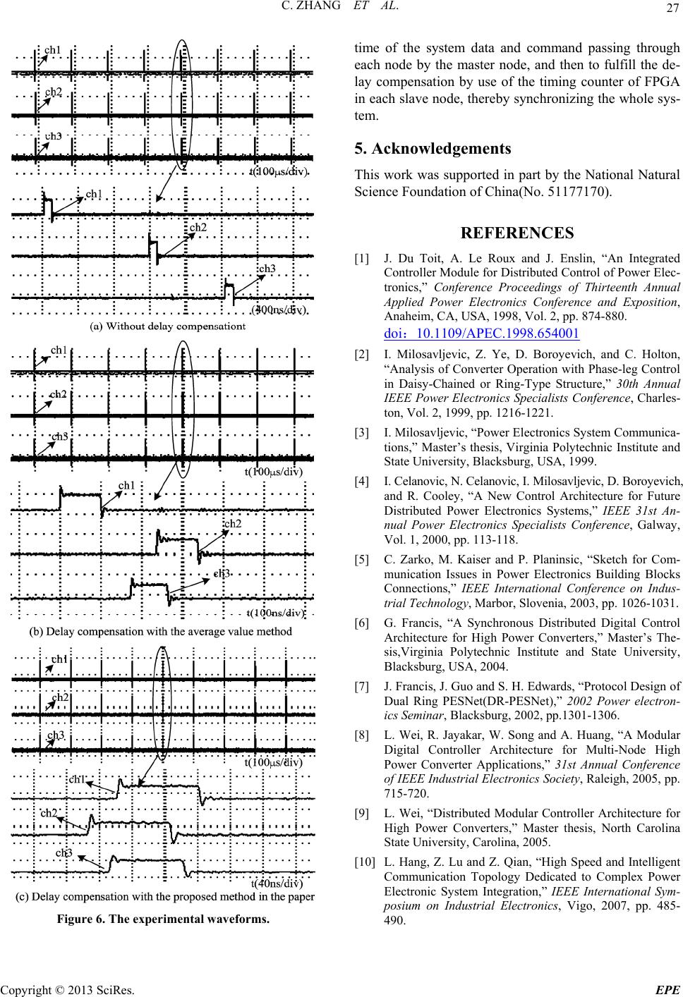
This paper has presented a method for the automatic
measurement and compensation of the system’s synchro-
nization delay. The method can automatically calculate
the overall network transmission delay and total number
of salve nodes of the system and can according to differ-
ent lengths of the fiber optical lines used, work out the
processing delay of communication data and command
through each slave node, thereby compensating for the
synchronization delay of each node in the system auto-
matically.
2. Synchronization of the High-speed Fiber
Optic Ring Net Communication Network
for the PECS
The topology of the high-power fifteen-phase propulsion
converter for marine propulsion is shown as Figure 1.
Each inverter unit and brake unit is regarded as a node.
There are 18 slave nodes altogether, with each node
equipped with a slave controller. The whole control net-
work is formed into a ring net with the communication
rate of 125 Mbps by a single optical fiber. It can be seen
from Figure 1 that the distance between nodes of the
system is unequal in the actual laying-out. For the con-
Copyright © 2013 SciRes. EPE
C. ZHANG ET AL. 25
verter as shown in Figure 1, the paper proposes a method
for automatic measurement and compensation of system
synchronization delay. The method can be used to auto-
matically calculate the processing delay of the system
data and command passing through each node according
to different lengths of the fiber-optic lines between the
nodes.
The model for measuring the system delay is shown as
Figure 2. The fixed fiber-optic transmission delay tdi(i=1,
2, 3, …, n+1) between the nodes is not equal. The struc-
tures and chips of each slave node in the system are the
same, so that the processing delay of the system data and
command passing through each slave node can be con-
sidered approximately equal, which is tavg. During the
initial period of the system, the master node sends a syn-
chronous sequence frame, whose format is shown as
Figure 3(a). The initial value of the node test address is
0. When each slave node receives its node test address,
the address will be obtained by adding 1 to this node’s
address and then retransmitted to the next node. There-
fore, the total number of the slave nodes of the whole
system will be derived when the node test address returns
to the master node.
Figure 1. The topology of the high power fifteen-phase
propulsion converter.
Figure 2. The model for measuring the system delay.
Figure 3. (a) The format of synchronous sequence frame (b)
The format of delay data transmitting frame.
The master node sends a synchronous sequence frame
and saves the transmission time tstart, and also the recep-
tion time tend when it receives the synchronous sequence
frame, as shown in Figure 2, it can be derived as:
totalend start
ttt=- (1)
1
1
1
n
total di
i
avg
tt
tn
+
=
-
=+
å
(2)
where ttotal is the total transmission delay of the whole
network and n is the number of slave nodes.
According to Figure 2 and equations (1)-(2), the
compensation delay of each slave node of the system can
be derived as:
()
(1)
2
(1)
()
1
0
n
comp diavg
i
comp ndnavg
comp n
ttn
ttt
t
=
-
ì
ï
ï=+-
ï
ï
ï
ï
ï
ï
í
ï
ï=+
ï
ï
ï
ï=
ï
ï
î
åt
(3)
where the tcomp(i)(i=1,2,3,…,nis the preset delay time
value of compensation for slave node. The slave node
can complete the delay compensation of the system ac-
cording to the value preset by the compensation timing
counter. In the case of the fiber-optic connecting lines
between the nodes that are equal in length, equation (3) is
also available. At this time, tdii=1,2,3,…,nare equal.
3. System Experiments
In order to verify the method for delay automatic meas-
urement proposed in the paper, and an actual ring control
network has been established for the purpose of the cor-
responding experiments. The control ring network used
in the experiments on the system is shown as Figure 2,
and the n is equal to 3. The adopted formats of data
communication frame are shown as Figure 3(a) and
Figure 3(b) respectively. A fiber-optic line with 6 meter
is used between the master node and the first slave node,
66 meter between the first slave node and the second
slave node, 6 meter between the second slave node and
the third slave node, and 6 meter between the third slave
node and the master node. As the fiber-optic line delay is
5ns/m, td1=td3=td4=30ns and td2=330ns.
Figures 4 and 5 respectively show the data communi-
cation waveforms of synchronization delay measured
from the master node and the slave nodes captured by the
signaltap II logic analyzer in quartus II, with 10ns as the
minimum scale of time used.
Figure 4 shows that the synchronization test command
sent by the master node is “1” and the node test address
is “0”. Through the whole ring network, the node test
address received by the master node turns out to “3”, so
Copyright © 2013 SciRes. EPE
C. ZHANG ET AL.
Copyright © 2013 SciRes. EPE
26
the total number of the slave nodes of the whole network
is “3”. Meanwhile, the total network delay of the whole
system is “365” obtained from the calculation by the
master node. Therefore, the network delay of the whole
system is 3650ns. Similarly, the processing delay of the
system data and command passing through each node is
810ns. Figure 5(a) indicates that the node test address
received by the slave node 1 is “0” and is transmitted as
“1”. In Figure 5(b), the node test address received by the
salve node 2 is “1” and is transmitted as “2”. In Figure 5
(c), the node test address received by the slave node 3 is
“2” and t is transmitted as “3”. From Figures 4 and 5, it
is found that the system works normally.
In order to demonstrate the correctness and feasibility
of the method proposed in the paper, different lengths of
the fiber-optic lines are used between the nodes, as shown
in Figure 2. The synchronization experiments without
delay compensation, with delay compensation by average
value method and with delay compensation by the pro-
posed method in the paper are carried out respectively.
The experimental waveforms are shown as from Figures
6(a)-(c). The channels of ch1, ch2 and ch3 represent the
synchronization flags of slave node 1, slave node 2 and
slave node 3 respectively. Figure 6(a) shows the ex-
perimental waveforms without delay compensation. Ac-
cording to the analysis of above, the theoretical delay
time value between slave node 1 and slave node 2 is
1.14μs and that between slave node 2 and slave node 3 is
840ns. Figure 6(a) shows the delay time between slave
node 1 and slave node 2 is about 1.13μs and that between
slave node 2 and slave node 3 is about 840ns, which ba-
sically conform to the theoretical values. Figure 6(b)
shows the experimental waveforms with delay compen-
sation by average value method. There appears a large
error in delay between the generated synchronization
flags due to the fiber-optic lines with different length.
Figure 6(b) shows the delay between slave node 1 and
slave node 2 is about 240ns and that between slave node
2 and slave node 3 is about 70ns. Figure 6(c) shows the
experimental waveforms with the proposed method in the
paper. The waveforms derived in Figure 6(c) are given
delay compensation according to equation (3). Figure
6(c) indicates that the system is well synchronized, with
small delay between the generated flags,that is about
33ns between slave node 1 and slave node 2 and about
24ns between slave node 2 and slave node 3.
4. Conclusions
The existing synchronization methods for fiber optic ring
network communication don’t take into account the ef-
fect of the lengths of fiber optic-lines between the nodes
on the system’s synchronization delay compensation. For
this reason, this paper has proposed a method for the
automatic measurement and compensation of synchroni-
zation delay based on high-speed fiber-optic ring net-
work communication. Using this method, it is possible to
automatically calculate the total network delay and the
number of slave nodes of the whole system by using the
master node to send a synchronous sequence frame. Ac-
cording to the network delay and the number of slave
nodes, it is convenient to calculate the processing delay
Figure 4. The communication data of delay automatically measured from the master node.
Figure 5. The communication data of delay automatically measured from the slave nodes (1~3).
C. ZHANG ET AL. 27
Figure 6. The experimental waveforms.
time of the system data and command passing through
each node by the master node, and then to fulfill the de-
lay compensation by use of the timing counter of FPGA
in each slave node, thereby synchronizing the whole sys-
tem.
5. Acknowledgements
This work was supported in part by the National Natural
Science Foundation of China(No. 51177170).
REFERENCES
[1] J. Du Toit, A. Le Roux and J. Enslin, “An Integrated
Controller Module for Distributed Control of Power Elec-
tronics,” Conference Proceedings of Thirteenth Annual
Applied Power Electronics Conference and Exposition,
Anaheim, CA, USA, 1998, Vol. 2, pp. 874-880.
doi10.1109/APEC.1998.654001
[2] I. Milosavljevic, Z. Ye, D. Boroyevich, and C. Holton,
“Analysis of Converter Operation with Phase-leg Control
in Daisy-Chained or Ring-Type Structure,” 30th Annual
IEEE Power Electronics Specialists Conference, Charles-
ton, Vol. 2, 1999, pp. 1216-1221.
[3] I. Milosavljevic, “Power Electronics System Communica-
tions,” Master’s thesis, Virginia Polytechnic Institute and
State University, Blacksburg, USA, 1999.
[4] I. Celanovic, N. Celanovic, I. Milosavljevic, D. Boroyevich,
and R. Cooley, “A New Control Architecture for Future
Distributed Power Electronics Systems,” IEEE 31st An-
nual Power Electronics Specialists Conference, Galway,
Vol. 1, 2000, pp. 113-118.
[5] C. Zarko, M. Kaiser and P. Planinsic, “Sketch for Com-
munication Issues in Power Electronics Building Blocks
Connections,” IEEE International Conference on Indus-
trial Technology, Marbor, Slovenia, 2003, pp. 1026-1031.
[6] G. Francis, “A Synchronous Distributed Digital Control
Architecture for High Power Converters,” Master’s The-
sis,Virginia Polytechnic Institute and State University,
Blacksburg, USA, 2004.
[7] J. Francis, J. Guo and S. H. Edwards, “Protocol Design of
Dual Ring PESNet(DR-PESNet),” 2002 Power electron-
ics Seminar, Blacksburg, 2002, pp.1301-1306.
[8] L. Wei, R. Jayakar, W. Song and A. Huang, “A Modular
Digital Controller Architecture for Multi-Node High
Power Converter Applications,” 31st Annual Conference
of IEEE Industrial Electronics Society, Raleigh, 2005, pp.
715-720.
[9] L. Wei, “Distributed Modular Controller Architecture for
High Power Converters,” Master thesis, North Carolina
State University, Carolina, 2005.
[10] L. Hang, Z. Lu and Z. Qian, “High Speed and Intelligent
Communication Topology Dedicated to Complex Power
Electronic System Integration,” IEEE International Sym-
posium on Industrial Electronics, Vigo, 2007, pp. 485-
490.
Copyright © 2013 SciRes. EPE