Journal of Surface Engineered Materials and Advanced Technology
Vol.09 No.04(2019), Article ID:95880,19 pages
10.4236/jsemat.2019.94007
Erosion and Toughening Mechanisms of Electroless Ni-P-Nano-NiTi Composite Coatings on API X100 Steel under Single Particle Impact
Marissa MacLean1, Zoheir Farhat1, George Jarjoura1, Eman Fayyad2,3, Aboubakr Abdullah2, Mohammad Hassan2
1Department of Mechanical Engineering, Dalhousie University, Halifax, Canada
2Center for Advanced Materials, Qatar University, Doha, Qater
3Physical Chemistry Department, National Research Center, Dokki, Giza, Egypt

Copyright © 2019 by author(s) and Scientific Research Publishing Inc.
This work is licensed under the Creative Commons Attribution International License (CC BY 4.0).
http://creativecommons.org/licenses/by/4.0/


Received: September 2, 2019; Accepted: October 19, 2019; Published: October 22, 2019
ABSTRACT
The addition of superelastic NiTi to electroless Ni-P coating has been found to toughen the otherwise brittle coatings in static loading conditions, though its effect on erosion behaviour has not yet been explored. In the present study, spherical WC-Co erodent particles were used in single particle impact testing of Ni-P-nano-NiTi composite coatings on API X100 steel substrates at two average velocities—35 m/s and 52 m/s. Erosion tests were performed at impact angles of 30˚, 45˚, 60˚, and 90˚. The effect of NiTi concentration in the coating was also examined. Through examination of the impact craters and material response at various impact conditions, it was found that the presence of superelastic NiTi in the brittle Ni-P matrix hindered the propagation of cracks and provided a barrier to crack growth. The following toughening mechanisms were identified: crack bridging and deflection, micro-cracking, and transformation toughening.
Keywords:
Electroless Ni-P Composite Coating, Superelastic NiTi, Single Particle Impact, Erosion Mechanisms, Toughening

1. Introduction
Impacting of surfaces with hard particles, typically known as solid particle erosion, can result in material removal, or even fracture of the surface [1] [2]. This is a common issue in aerospace and oil and gas applications where components such as jet engine compressor blades or pipeline walls are subject to impacting contaminants taken in through air flow, or sand carried through oil and gas, respectively [1] [2] [3]. Plain carbon steels are commonly used in oil and gas applications, particularly as the pipeline material. These pipe materials are subject to wear from particulates or contaminants contained in the oil or gas being transported. There are many variables that can affect the severity and mechanism of the erosion, including the impact angle, the velocity of the erosive particle hitting the material, and the properties of the erosive particle [4] [5]. Particle shape has a significant influence over the erosion mechanism and the amount of material removed. In particular, for spherical shaped impact particles, like the ones used in this study, it has been found in the literature that ductile materials exhibit lower material removal rates in comparison to those found for brittle materials under impact of the same spherical particles [6]. It has been well documented that for ductile material removal rates increase until a maximum between 30˚ - 45˚ and then subsequently decline. On the other hand, for brittle materials, the maximum material removal rate occurs at an angle normal to the surface [7] [8] [9].
Ni-P coatings make an excellent candidate for protective pipeline coatings due to their superior wear and corrosion resistance [10] [11] [12]. However, by nature, monolithic Ni-P coatings have low toughness upon deposition. The addition of nano-particles to electroless Ni-P coatings has found to enhance several properties [10] [12]. Brittle materials tend to fracture, similar to the fracture seen with indentation. For protective coatings, which tend to be hard and wear resistance but brittle, crack initiation and propagation tend to be the dominant failure mechanism under erosive conditions [13]. The addition of superelastic NiTi serves to toughen the brittle Ni-P matrix that occurs upon deposition. Recent work has shown that the NiTi particles within the Ni-P matrix result in toughening of the composite coating under indentation and scratch conditions [14]. Due to the fact that NiTi undergoes a reversibly martensitic phase transformation, transformation toughening can occur. As a crack begins to propagate, the high energy at the crack tip will induce a martensitic transformation in the superelastic particles. This transformation is accompanied by a distortion in crystal lattice, which in turn causes a compressive strain around the particles. This compression can stop the crack from propagating and even close the crack. This phenomenon has also been seen in zirconia reinforced ceramics such as thermal barrier coatings [15] [16] [17].
Ductile reinforcements in a brittle matrix have been found to toughen through several other mechanisms, including crack deflection and bridging, and micro-cracking [18] [19] [20]. All mechanisms have been found to increase the energy required for propagation of cracks, subsequently increasing the fracture toughness of the material being toughened. For example, crack deflection involves the interaction of a second phase particle with a propagating crack. When the crack comes into contact with a particle or fibre, the crack path must change course, reducing the energy at the crack wake [21] [22]. Crack bridging is also commonly seen in reinforced composites, where again the propagation energy is significantly increased upon interaction with a second phase. In order to continue, the crack must pass through the second phase, which essentially absorbs some of the crack energy in order to bridge the crack [23] [24]. Lastly, micro-cracking has been found to also increase fracture toughness by reducing major cracks to a series of micro-cracks [25].
Single particle erosion is useful in determining erosion mechanisms. Several works in the literature have examined erosion mechanisms using single particle erosion [26] [27] [28] [29] ; however, the literature regarding the single impact of composite materials is limited. As composite materials become more popular in industry, classification of their behaviour under erosion behavior becomes necessary. Solid particle erosion (multiple impact) of composites has been studied recently in the literature, particularly of coatings for materials undergoing wear and erosive conditions, due to the increasing popularity of ductile-reinforced brittle materials [30]. The objective of this study is to determine the erosion mechanisms of electroless Ni-P-nano-NiTi composite coatings using single particle impact. The present work addresses the single particle impact of electroless Ni-P based composite coatings with superelastic NiTi additions. The effects of the impact angle, velocity, and particle shape on the erosion behavior of the coatings are investigated. Toughening mechanisms due to the addition of NiTi particles are discussed.
2. Methodology
2.1. Materials
API X100 pipe steel discs (16 mm diameter, 6 mm thick), consisting of a bainitic and ferritic microstructure, were used as a substrate for each coating. Commercially made superelastic spherical NiTi particles from US Research Nanomaterials Inc. were used as ductile phase reinforcements for this study. The particles have an average size of 60 nm. SEM image of the particles in Figure 1(a) shows a wide size distribution and spherical particle morphology. WC-6 wt% Co particles having a nominal 1 mm diameter (Figure 1(b)) were fired at the samples due to their high hardness (75 HRC). The elastic modulus and Poisson’s ratio for the erodent material have been found in the literature to be approximately 600 GPa and 0.26, respectively [31].
 (a)
(a)
 (b)
(b)
Figure 1. SEM images of (a) nano-NiTi particles and (b) WC-Co erodent particle respectively.
2.2. Coating Preparation
Each substrate was ground using 240, 320, 400, and 600 grit SiC abrasive paper and then polished using 9 μm, 3 μm, and 1 μm monocrystalline diamond polish. The substrates were then degreased in acetone and cleaned in an alkaline solution at 80˚C ± 5˚C. The contents of the alkaline cleaning solution used in substrate pre-treatment include 50 g/L sodium hydroxide, 30 g/L sodium carbonate, and 40 g/L sodium phosphate. Samples were then rinsed with deionized water and etched for 10 s using H2SO4. Samples were rinsed again with deionized water and hung horizontally in a commercial electroless Ni-P plating bath (Figure 2), which contained sodium hypophosphite (NaPO2H2) as the reducing agent and nickel sulfate (NiSO4) as the source of Ni. Samples were hung horizontally in the electroless bath for 30 minutes in order to form a pre-coat layer of monolithic Ni-P. After the pre-coating, the samples were removed and put in an electroless Ni-P plating bath containing varying amounts of superelastic NiTi nano-powder. Magnetic stirring was employed at 300 RPM throughout the duration of the coating process. The temperature of each plating bath was maintained at 88˚C ± 2˚C, and the pH was maintained between 4.5 - 5.2, adding NH4OH as necessary to raise the pH.

Figure 2. Electroless plating bath set-up used for coating samples.
2.3. Single Particle Erosion Testing
Coated samples containing 0.5, 1 and 2 g of NiTi were tested under several different conditions using a single particle erosion tester in order to gain an understanding of the effect of impact angle and particle velocity on the erosion mechanisms. Figure 3(a) shows the typical cross-section of the coating. There is a uniform distribution of particles throughout the coating, and evidence of good adhesion to the substrate (no voids at coating/substrate interface). All composite coatings had relatively uniform thickness throughout the entirety of the coating. Although the nano-particles have a wide size distribution, due to this uniform dispersion of particles, the properties of the coating are expected to be uniform throughout the entirety of the coating. Figure 3(b) shows the surface morphology of the composite coating. The coating roughness of the composite coatings has been shown in previous work to increase in comparison to the monolithic Ni-P coatings [14].
Prior to testing, each coated sample was ground using 600 grit SiC and polished using 9 μm and 3 μm Beuhler MetaDi diamond polish. Each sample was tested at angles of 30˚, 45˚, 60˚, and 90˚. The samples were also tested at low pressures (30 psi) and high pressures (60 psi). Energy Dispersive Spectroscopy (EDS) and micro-Vickers hardness were done on the cross-sections of each sample in order to confirm the amount of NiTi in the coating and the average hardness respectively. These properties, as well as the hardness of the steel substrate, can be seen in Table 1.
A schematic of the apparatus used for the experiments can be found in Figure 4. The system is driven by a compressed air supply, the pressure of which is
 (a)
(a)
 (b)
(b)
Figure 3. SEM image of (a) coating cross-section and (b) coating surface morphology.

Table 1. Material properties of coatings and the substrate used in this study.
adjusted to vary the velocity of the particle. Air is fed to the system by means of an actuation mechanism that is triggered by a button. This results in the opening of a solenoid valve, which allows air to flow through the system and drive the particle down a polycarbonate barrel. The angle at which the target sample was at was varied using the sample holder.
Two photo-interrupters were placed at the end of the barrel, 3 cm apart. By measuring the time required for the particle to travel between the two photo-interrupters (PIs), the velocity can be calculated using Equation (1). A velocity calibration curve was formulated by assessing the velocity at pressures varying between 20 - 60 psi (Figure 5). As seen in the figure, testing pressures for this work correspond to average velocities of 35 ± 3 m/s and 52 ± 4 m/s.
(1)
By assuming ideal conditions, the force of the particle can be estimated using Equations (2) and (3):
(2)
(3)
where W is the work done creating the impact crater, F is the force, d is the distance that the particle travels, Ek is the kinetic energy of the particle based on the

Figure 4. Schematic of set-up used for single particle erosion testing.

Figure 5. Velocity calibration curve as a function of testing pressure.
mass (mp) and the velocity (v). Assuming that all kinetic energy is transformed into work that is done to create the impact crater, the impact force was found to range between 0.016 - 0.036 N for velocity conditions 35 - 52 m/s respectively.
Impacted samples were examined using optical microscopy (OM) and scanning electron microscopy (SEM) in order to determine erosion mechanisms and to investigate for toughening mechanisms. Volume loss was examined using a Keyence laser confocal microscope.
3. Results
3.1. Material Removal and Cracking Behaviour
Volume loss was determined for each sample under all single particle impact conditions. Figure 6(a) shows the effect of impact angle on volume loss at operating velocity of 35 m/s for all coatings. Figure 6(b) shows the correlation between volume loss and impact angle for each coating tested at 52 m/s. In comparison, samples tested at 35 m/s had smaller impact craters relative to the samples tested at 52 m/s, which is similar to results found in the literature [7] [32]. The 5.14 wt% NiTi and 7.02 wt% NiTi coatings experienced the highest volume loss at 90˚, which is typical of brittle materials [33]. On the other hand, the 6.07 wt% NiTi coating exhibited the highest volume loss at 45˚, consistent with the behaviour of ductile materials [7]. Therefore, in terms of material removal,
 (a)
(a) (b)
(b)
Figure 6. Volume loss as a function of impact angle with average testing velocity of (a) 35 m/s and (b) 52 m/s.
the 6.07 wt% coating can be classified as the toughest relative to the other coatings in the present work. Furthermore, even at a low impact velocity of 35 m/s, the 6.07 wt% NiTi coating exhibits a ductile behaviour (Figure 6(a)). Here, the maximum erosion volume loss takes place at an impact angle of 45˚ and drops as the impact angle is increased to 90˚. However, the ductile characteristics at low velocities are less pronounced than at high velocities.
Select SEM was done on low and high angle impact sites of the 6.07 wt% NiTi coating to examine the erosion mechanisms. The impact crater subjected to high impact angle is circular, while that impacted at low angle is elliptical in shape, as seen in Figure 7. The size of the normal impact crater is larger than that of the low angle impact, as expected, due to the fact that more energy was transferred to forming the crater, whereas in the case of the low angle impact, some of that initial kinetic energy is dissipated due to frictional forces [1] [34]. Evidence of cracking was seen in the composite coatings, as evident in the optical images of the 6.07 wt% NiTi in Figure 7. Cracks appear to be shallow and concentrated in the vicinity of the impact crater. Radial and ring cracks are present at both low and high angle impacts in the Ni-P matrix. It is believed that ring cracks are Hertzian-type. Evidence of closed cracks was also seen in the inside of the impact sites. An example of this can be seen in Figure 8.


Figure 7. Erosion crater showing evidence of Hertzian and radial cracking in 6.07 wt% NiTi sample at (a) low angle and (b) high angle impact.

Figure 8. Network of closed cracks in impact crater of 6.07 wt% NiTi coating under normal impact.
Figure 9 shows the 3D surface and line profiles of the impact craters at high and low angle. Crater depths are higher at normal impact due to the fact that nearly all energy is transformed into work being done to form the crater, while at lower angles frictional forces reduce the work that can be done [34] [35]. It is evident that the impact craters formed by squeezing the material outside the crater. At low impact angles, pile-up forms behind the impacting particle as it contacts the coating surface. This can be seen in the line profile at the center of the crater and along the major axis of the elliptical crater (Figure 9(a), Figure 9(b)). The normal impact reveals that material build-up forms evenly around the edges of the crater, as seen in Figure 9(c), Figure 9(d).
3.2. Evidence of Toughening
As the purpose of adding NiTi to the matrix is to toughen it, SEM was done to identify and examine any toughening mechanisms in the coatings. EDS mapping (Figure 10) confirmed a uniform distribution of particles in the matrix, which allows for the assumption that toughening effects are consistent across the sample.
Examples of all aforementioned mechanisms are given and discussed. Figure 11(a) shows evidence of crack deflection in the impact crater due to the presence of a NiTi particle. Presence of NiTi particles was confirmed using EDS mapping, as seen in Figure 11(b). Crack bridging was also seen in the composite coatings (Figure 12), where the crack must interact with the NiTi particle before propagating further, resulting in a change in propagation energy.

Figure 9. Respective 3D surface and depth profiles of (a), (b) low impact and (c), (d) high impact for 6.07 wt% NiTi coating.

Figure 10. EDS map showing nano-NiTi particle distribution on 6.07 wt% NiTi coating surface.


Figure 11. (a) SEM image and (b) EDS map of evidence of crack deflection in 6.07 wt% NiTi composite coating under normal impact.

Figure 12. Evidence of crack bridging in 6.07 wt% NiTi composite coating under normal impact.
Micro-cracking was observed in the composite coatings at both high and low angle impact. Evidence of this can be seen in Figure 13. The presence of superelastic NiTi particles in the matrix may break up larger cracks into micro-cracks.
In order to initiate the reversible martensitic transformation, the contact stress as a result of particle impact must be greater than the transition stress. In the literature, this stress has been reported to be approximately 410 MPa at room temperature [36]. From the forces calculated in Section 2.3, it is necessary to calculate the mean contact pressure (pm) to ensure that it is greater than the transition stress. By using Hertzian contact theory (described by Equations (4)-(6) below), pm, where a = contact radius, P = applied load, r = radius of WC-Co particles, and E* is the effective elastic modulus, this can be confirmed.
(4)
(5)
(6)
Assuming that E and v are the values for WC outlined above, and E' and v' for Ni-P are 198 GPa and 0.29 [37] respectively, it was found that pm ranges between 460 - 600 MPa and thus is high enough to initiate the transformation from austenite to martensite. Evidence of transformation toughening was observed in the impact sites of the coatings (Figure 14). While examining the coatings under SEM, it was noticed that in many cases, cracks would not be deflected or bridged by the particles; rather they would surround the particles without ever coming into contact with the second phase. The fact that the cracks are surrounding the superelastic NiTi particle (insert of Figure 14) provides a strong indication that a compression field around the particle prevents the cracks from propagating through this field. As the particle shown is within the impact site, it is likely that the compression force discussed previously worked in combination with transformation toughening to close the crack shown.

Figure 13. SEM image of extensive network of microcracks observed at the edge of impact site of 6.07 wt% NiTi under normal impact.

Figure 14. Closed crack network surrounding NiTi particle in 6.07 wt% NiTi composite coating.
4. Discussion
4.1. Erosion Mechanisms
Minimal change in volume loss was seen with a change in angle, suggesting that at lower velocities impact angle has minimal effect on material removal. At low velocities the eroding particle has lower energy hence, its ability to induce permanent deformation and fracture is limited. The ratio of elastic to plastic deformation is high, i.e., a significant portion of the impact energy is consumed in deforming the coatings elastically. This trend has also been seen for materials in solid particle erosion [7]. From this analysis, it is clear that the 6.07 wt% NiTi coating performed better under the velocity conditions used in this study. It is likely that the 5.14 wt% NiTi coating did not contain enough superelastic NiTi to drastically change the behaviour. On the other hand, the 7.02 wt% NiTi coating likely contained too high of a concentration of nano-particles, leaving the samples subject to agglomeration and higher stress concentrations on the surface. This could result in more fracture, consistent with a brittle material. Therefore the 6.07 wt% NiTi contained the optimal concentration of NiTi particles for this study.
Both Hertzian and radial cracking was present in the composite coatings at both low and high angle impacts. It is interesting to note that at lower angles (i.e. 30˚), Hertzian cracking occurs at the initial point of contact but not on the other side of the crater where the impacting particle leaves the surface. This is similar to cohesive failure during silding contact, where Hertzian-type cracks are a result of tensile stress behind the indenter [9]. However, radial cracks do not appear on the side of the crater where the initial impact takes place, but are clearly seen on the opposite side. This finding suggests that cracking pattern is incident angle dependent in erosive processes. Here, the behaviour could be attributed to the changes in the stress distribition during low angle impact. In the case of higher impact angles (i.e. 90˚), Hertzian and radial cracking is present around the perimeter of the impact crater similar to static indentation loading. There is also a closed crack network inside the crater as a result of erodent particle induced compaction. Upon initial impact, cracks begin to initiate and propagate at stress concentrations throughout the matrix. As the particle pushes through the surface, two things may occur. The first, being that due to the compression forces, the cracks that form on initial impact eventually close shut as the particle travels through the material. Secondly, these cracks are forced to close due to the stress associated with volume expansion of the superelastic particles during transformation from austenite to martensite (discussed in more detail below).
Hertzian-type cracks form on the surface just outside the contact area where the radial stress reaches its maximum tensile value [38] [39]. Radial cracks also develop on the surface but are caused by the maximum tensile hoop stress [40]. Hoop stress becomes positive (tension) on the surface during elastic-plastic contact which applies to the present study [41]. Both radial and ring cracks initiated when the applied load exceeded a critical value. In a recent study, Yonezu et al. [35] investigated fracture mechanisms of electroplated Ni-P on steel under static indentation conditions. They suggested that ring crack formation alters the subsequent stress distribution during indentation; as a result tensile hoop stress develops upon unloading. They also proposed that radial cracks initiate near the ring crack tip at the coating/substrate interface.
It is clear from the results that pile-up form outside the impact crater. The pile-up creates tensile stresses that further promote Hertzian-type cracks development in the coating as previously seen in the optical images. Similar to low angle impact, material build-up induces tensile stresses around the crater and assists in initiating Hertzian type cracks. As described earlier, the cracks on coatings subjected to both low and high impact angles appear to be shallow and occur at the top surface layers where tensile stresses are highest.
4.2. Toughening Mechanisms
The results show several examples of toughening in the composite coatings, due to the addition of the superelastic NiTi nano-particles. As the cracks initiate through the Ni-P matrix, the propagation energy is significantly reduced by deflection, bridging, micro-cracking and transformation toughening as the crack approaches the ductile NiTi particle. Without superelastic additions, the matrix would be subject to further crack propagation and failure.
Upon impact, the NiTi particles can act as obstacles to crack propagation, which can force a crack to change direction (crack deflection). In doing so, the crack uses energy to change direction, and the driving force at the crack wake is reduced. When a propagating crack approaches a particle, the propagation energy can be absorbed by the ductile particle, reducing its energy as it continues (crack bridging). This, like crack deflection, reduces the severity of the crack. Both toughening mechanisms have been seen in the literature when micro and nano-sized particle were added to a ceramic matrix, with the additions clearly dictating the cracking path [42] [43].
Another form of toughening mechanisms seen was micro-cracking. While the formation of major cracks in materials is typically undesirable, it has been found that the formation of micro-cracks near the initial crack site can be beneficial in increasing fracture toughness in brittle materials [44] [45]. In composites, micro-cracking has been found to be beneficial in reducing energy that would otherwise propagate major cracks. In the process of crack deflection and bridging, larger cracks may break up into finer cracks.
Crack closing as a result of transformation toughening is believed to be due to a compression field that is generated around the particles whilst undergoing a volumetric change due to the stress induced martensitic transformation from austenite to martensite. When a crack attempts to propagate through or near a particle, the tensile stress is high enough around the crack such that the transition stress is reached, and the superelastic particles undergo a change from austenite to martensite. This compression force can cause the cracks near the particles to close. This is important in order to avoid propagation of major cracks, and it has been seen in ZrO2 alloys that are capable of undergoing the same martensitic transformation [17] [46] [47]. Similar results have been seen under static indentation with superelastic NiTi [14].
4.3. Summary
Erosion and toughening mechanisms of the Ni-P-nano-NiTi composite coatings are summarized in the following schematics. Under low-angle impact, the composite coated surface shows evidence of Hertzian fracture upon initial impact (Figure 15(a)), followed by the propagation of radials in the direction of impact. It was found that upon normal impact (Figure 15(b)), where the highest energy is transferred to producing the impact crater, an intricate network of Hertzian and radial cracks are seen in the composite coatings. These mechanisms for both angles are also coupled with toughening mechanisms due to the addition of superelastic NiTi, including crack deflection/ bridging, micro-cracking and transformation toughening. The following sequence of events has been derived from the present study for the composite coatings:
1) WC-Co particle hits the coated surface, inducing stress on the surface.
2) Material is squeezed to the side of the impact in order to form an impact crater.
3) Hertzian cracks initiate and propagate in the Ni-P matrix, which has low fracture toughness.
4) The change in stress distribution due to Hertzian cracking initiates radial cracking and propagating in the Ni-P matrix.
5) As the particle travel through the material, high compression forces can cause cracks inside the stress field to close.
6) Cracks continue to propagate until they come into contact with superelastic NiTi particles which either bridge, deflect, or close the cracks completely inside and outside of the contact stress field.
 (a)
(a)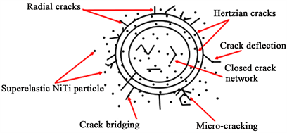 (b)
(b)
Figure 15. Schematic of erosion and toughening mechanisms of composite coated surface under (a) low angle impact and (b) normal impact.
5. Conclusion
The objective of the present work was to produce a coating that exhibited high toughness under erosion conditions by adding superelastic NiTi nano-particles to electroless Ni-P coating matrix. Composite coating containing 6.07 wt% NiTi showed a significant reduction in cracking throughout the Ni-P matrix. Due to the fact that the superelastic particles incorporated into the matrix undergo a reversible martensitic transformation, transformation toughening took place. Other toughening mechanisms such as crack bridging, micro-cracking, and crack deflection were also seen. The ability of this composite coating to minimize the presence of major cracks and increase fracture toughness gives the coating potential to be used in a multitude of tribological applications, where the otherwise brittle monolithic Ni-P matrix would fail.
Acknowledgements
This publication was made possible by NPRP grant #NPRP8-1212-2-499 from the Qatar National Research Fund (a member of Qatar Foundation). The findings achieved herein are solely the responsibility of the authors.
Conflicts of Interest
The authors declare no conflicts of interest regarding the publication of this paper.
Cite this paper
MacLean, M., Farhat, Z., Jarjoura, G., Fayyad, E., Abdullah, A. and Hassan, M. (2019) Erosion and Toughening Mechanisms of Electroless Ni-P-Nano-NiTi Composite Coatings on API X100 Steel under Single Particle Impact. Journal of Surface Engineered Materials and Advanced Technology, 9, 88-106. https://doi.org/10.4236/jsemat.2019.94007
References
- 1. Bousser, E., Martinu, L. and Klemberg-Sapieha, J. (2014) Solid Particle Erosion Mechanisms of Protective Coatings for Aerospace Applications. Surface & Coatings Technology, 257, 165-181. https://doi.org/10.1016/j.surfcoat.2014.08.037
- 2. Alidokht, S.A., Vo, P., Yue, S. and Chromik, R.R. (2017) Erosive Wear Behavior of Cold-Sprayed Ni-WC Composite Coating. Wear, 376-377, 566-577. https://doi.org/10.1016/j.wear.2017.01.052
- 3. Parsi, M., Kamyar, N., Najafifard, F., Hassani, S. and McLaury, B.S. (2014) A Comprehensive Review of Solid Particle Erosion Modeling for Oil and Gas Wells and Pipeline Applications. Journal of Natural Gas Science and Engineering, 21, 850-873. https://doi.org/10.1016/j.jngse.2014.10.001
- 4. Islam, M.A., Farhat, Z.N. and Ahmed, E.M. (2012) Influence of Impact Angle and Velocity on Erosion of AISI 1018 Steel under Jet Impingement. Proceedings of the 3rd International Gas Processing Symposium, Doha, March 2012, 274-279.
- 5. Nsoesie, S., Liu, R., Chen, K. and Yao, M. (2014) Analytical Modeling of Solid-Particle Erosion of Stellite Alloys in Combination with Experimental Investigation. Wear, 309, 226-232. https://doi.org/10.1016/j.wear.2013.11.026
- 6. Naveed, M., Schlag, H., Konig, F. and Sabine, W. (2017) Influence of the Erodent Shape on the Erosion Behavior of Ductile and Brittle Materials. Tribology Letters, 65, 1-9. https://doi.org/10.1007/s11249-016-0800-x
- 7. Islam, M.A. and Farhat, Z.N. (2014) Effect of Impact Angle and Velocity on Erosion of API X42 Pipeline Steel under High Abrasive Feed Rate. Wear, 311, 180-190. https://doi.org/10.1016/j.wear.2014.01.005
- 8. Bull, S. (2006) Using Work of Indentation to Predict Erosion Behavior in Bulk Materials and Coatings. Journal of Physics D: Applied Physics, 39, 1626-1634. https://doi.org/10.1088/0022-3727/39/8/023
- 9. Roy, M. (2015) Thermal Sprayed Coatings and Their Tribological Performances. IGI Global, Hershey. https://doi.org/10.4018/978-1-4666-7489-9
- 10. Fayyad, E.M., Abdullah, A.M., Hassan, M.K., Mohamed, A.M. and Jarjoura, G. (2018) Recent Advances in Electroless-Plated Ni-P and Its Composites for Erosion and Corrosion Applications: A Review. Emergent Materials, 24, 3-23. https://doi.org/10.1007/s42247-018-0010-4
- 11. Wang, C. (2017) Indentation and Fracture Behaviour of Electroless Ni-P-Based Composite Coatings. Dalhousie University, Halifax.
- 12. Sadeghzadeh-Attar, A., AyubiKia, G. and Ehteshamzadeh, M. (2016) Improvement in Tribological Behavior of Novel Sol-Enhanced Electroless Ni-P-SiO2 Nanocomposite Coatings. Surface and Coatings Technology A, 307, 837-848. https://doi.org/10.1016/j.surfcoat.2016.10.026
- 13. Bousser, E., Martinu, L. and Klemberg-Sapieha, J.E. (2013) Effect of Erodent Properties on the Solid Particle Erosion Mechanisms of Brittle Materials. Journal of Materials Science, 48, 5543-5558. https://doi.org/10.1007/s10853-013-7349-y
- 14. MacLean, M., Farhat, Z., Jarjoura, G., Fayyad, E., Abdullah, A. and Hassan, M. (2019) Fabrication and Investigation of the Scratch and Indentation Behaviour of New Generation Ni-P-Nano-NiTi Composite Coating for Oil and Gas Pipelines. Wear, 426-427, 265-276. https://doi.org/10.1016/j.wear.2019.01.058
- 15. Tsukamoto, H. (2010) Design against Fracture of Functionally Graded Thermal Barrier Coatings Using Transformation Toughening. Materials Science and Engineering A, 527, 3217-3226. https://doi.org/10.1016/j.msea.2010.01.087
- 16. Filippov, R., Freidin, A., Hussainova, I. and Vilchevskaya, E. (2015) Critical Radius of Zirconia Inclusions in Transformation Toughening of Ceramics. Physical Mesomechanics, 18, 33-42. https://doi.org/10.1134/S1029959915010051
- 17. Hou, J., Li, Q., Lv, J. and Zuo, H. (2016) Crack Deflection by the Transformable Particles Dispersed in Composites. Acta Mechanica, 227, 743-756. https://doi.org/10.1007/s00707-015-1440-1
- 18. Alman, D. and Hawk, J. (2001) Abrasive Wear Behavior of a Brittle Matrix (MoSi2) Composite Reinforced with a Ductile Phase (Nb). Wear, 251, 890-900. https://doi.org/10.1016/S0043-1648(01)00747-5
- 19. Hillig, W., Raddatz, O., Schneider, A. and Claussen, N. (2001) Analysis and Model of the Crack Bridging Mechanisms in a Ductile Fiber Reinforced Ceramic Matrix Composite. Journal of Materials Science, 36, 1653-1663. https://doi.org/10.1023/A:1017535519524
- 20. Jang, J.S.-C. and Liu, C.-T. (2009) Structural and Mechanical Characterizations of Ductile Fe Particles-Reinforced Mg-Based Bulk Metallic Glass Composites. Journal of Alloys and Compounds, 485, 290-294. https://doi.org/10.1016/j.jallcom.2009.06.084
- 21. Barchiesi, M. (2018) Toughening by Crack Deflection in the Homogenization of Brittle Composites with Soft Inclusions. Archive for Rational Mechanics and Analysis, 227, 749-766. https://doi.org/10.1007/s00205-017-1173-5
- 22. Martin, E., Peters, P., Leguillon, D. and Quenisset, J. (1998) Conditions for Matrix Crack Deflection at an Interface in Ceramic Matrix Composites. Materials Science and Engineering: A, 250, 291-302. https://doi.org/10.1016/S0921-5093(98)00604-2
- 23. Warrier, S., Miracle, D., et al. (1997) Interface Effects on Crack Deflection and Bridging during Fatigue Crack Growth of Titanium Matrix Composites. Acta Materialia, 45, 4969-4980. https://doi.org/10.1016/S1359-6454(97)00179-1
- 24. Withers, P.J., Lopez-Crepso, P., Kyrieleis, A. and Hung, Y.-C. (2012) Evolution of Crack-Bridging and Crack-Tip Driving Force during the Growth of a Fatigue Crack in Ti/SiC Composite. Proceedings: Mathematical, Physical and Engineering Sciences, 468, 2722-2743. https://doi.org/10.1098/rspa.2012.0070
- 25. Singh, J.P., Hasselman, D., Su, W., Rubin, J. and Palicka, R. (1981) Observations on the Nature of Micro-Cracking in Brittle Composites. Journal of Materials Science, 16, 141-150. https://doi.org/10.1007/BF00552068
- 26. Sundararajan, G. (1981) The Nature of Plastic Deformation during Single Impact and Its Relevance to Solid Particle Erosion. The Ohio State University, Columbus.
- 27. Cenna, A., Page, N., Kisi, E. and Jones, M. (2011) Single Particle Impact Tests Using Gun and Analysis of High Strain-Rate Impact Events in Ductile Materials. Wear, 271, 1497-1503. https://doi.org/10.1016/j.wear.2010.11.023
- 28. Papini, M. and Dhar, S. (2006) Experimental Verification of a Model of Erosion Due to the Impact of Rigid Single Angular Particles on Fully Plastic Targets. International Journal of Mechanical Sciences, 48, 469-482. https://doi.org/10.1016/j.ijmecsci.2005.12.010
- 29. Dhar, S., Krajac, T., Ciampini, D. and Papini, M. (2005) Erosion Mechanisms Due to Impact of Single Angular Particles. Wear, 258, 567-579. https://doi.org/10.1016/j.wear.2004.09.016
- 30. Ramanujam, N. and Nakamura, T. (2009) Eorsion Mechanisms of Thermally Sprayed Coatings with Multiple Phases. Surface and Coatings Technology, 204, 42-53. https://doi.org/10.1016/j.surfcoat.2009.06.024
- 31. Neupane, R. (2014) Indentation and Wear Behavior of Superelastic TiNi Shape Memory Alloy, Halifax. https://doi.org/10.1007/s11661-014-2385-z
- 32. Lopez, D., Congote, J., Cano, J., Toro, A. and Tschiptschin, A.P. (2005) Effect of Particle Velocity and Impact Angle on the Corrosion-Erosion of AISI 304 and AISI 420 Stainless Steels. Wear, 259, 118-124. https://doi.org/10.1016/j.wear.2005.02.032
- 33. Oka, Y., Mihara, S. and Yoshida, T. (2009) Impact-Angle Dependence and Estimation of Erosion Damage to Ceramic Materials Caused by Solid Particle Impact. Wear, 267, 129-135. https://doi.org/10.1016/j.wear.2008.12.091
- 34. Lindroos, M., Apostol, M., Kuokkala, V.-T., Laukkanen, A., VAltonen, K., Holmberg, K. and Oja, O. (2015) Experimental Study on the Behavior of Wear Resistant Steels under High Velocity Single Particle Impacts. International Journal of Impact Engineering, 78, 114-127. https://doi.org/10.1016/j.ijimpeng.2014.12.002
- 35. Li, W.Y., Wang, J., Zhu, H., Li, H. and Huang, C. (2013) On Ultra High Velocity Micro-Particle Impact on Steels—A Single Impact Study. Wear, 305, 216-227. https://doi.org/10.1016/j.wear.2013.06.011
- 36. Farhat, Z., Jarjoura, G. and Shahirnia, M. (2013) Dent Resistance and Effect of Indentation Loading Rate on Superelastic TiNi Alloy. Metallurgical and Materials Transactions A, 44, 3544-3551. https://doi.org/10.1007/s11661-013-1727-6
- 37. Lin, C., Dadvand, N., Farhat, Z. and Kipouros, G.J. (2013) Electroless Nickel Phosphorous Plating on Carbon Steel. Materials Science and Technology Conference and Exhibition, Montreal, QC, Canada, October 2013, 2224-2237.
- 38. Lawn, B. (1998) Indentation of Ceramics with Spheres: A Century after Hertz. Journal of the American Ceramic Society, 81, 1977-1994. https://doi.org/10.1111/j.1151-2916.1998.tb02580.x
- 39. Johnson, K. (1985) Contact Mechanics. Cambridge University Press, Cambridge.
- 40. Lackner, J. (2014) Tribology and Micromechanics of Chromium Nitride Based Multilayer Coatings on Soft and Hard Substrates. Coatings, 4, 121-138. https://doi.org/10.3390/coatings4010121
- 41. Hardy, C., Baronet, C. and Tordion, G. (1971) The Elasto-Plastic Indentation of a Half-Space by a Rigid Sphere. International Journal for Numerical Methods in Engineering, 3, 451-462. https://doi.org/10.1002/nme.1620030402
- 42. Yin, Z., Huang, C., Zou, B., Liu, H., Zhu, H. and Wang, J. (2013) Study of the Mechanical Properties, Strengthening and Toughening Mechanisms of Al2O3/TiC Micro-Nano-Composite Ceramic Tool Material. Materials Science and Engineering: A, 577, 9-15. https://doi.org/10.1016/j.msea.2013.04.033
- 43. Tan, H. and Yang, W. (1998) Toughening Mechanisms of Nano-Composite Ceramics. Mechanics of Materials, 30, 111-123. https://doi.org/10.1016/S0167-6636(98)00027-1
- 44. Vashishth, D., Tanner, K. and Bonfield, W. (2003) Experimental Validation of a Microcracking-Based Toughening Mechanism for Cortical Bone. Journal of Biomechanics, 36, 121-124. https://doi.org/10.1016/S0021-9290(02)00319-6
- 45. Zhu, B., Xue, X., Kou, H., Li, X. and Li, J. (2018) Effect of Microstructure on the Fracture Toughness of Multi-Phase High Nb-Containing TiAl Alloy. Intermetallics, 100, 142-150. https://doi.org/10.1016/j.intermet.2018.06.014
- 46. Song, M., He, S., Du, K., Huang, Z., Yao, T., Hao, Y., Li, S., Yang, R. and Ye, H. (2016) Transformation Induced Crack Deflection in a Metastable Titanium Alloy and Implications on Transformation Toughening. Acta Materialia, 118, 120-128. https://doi.org/10.1016/j.actamat.2016.07.041
- 47. Hannink, R.H., Kelly, P.M. and Muddle, B.C. (2000) Transformation Toughening in Zirconia-Containing Ceramics. Journal of American Ceramic Society, 83, 461-487. https://doi.org/10.1111/j.1151-2916.2000.tb01221.x