Circuits and Systems
Vol.07 No.11(2016), Article ID:70640,11 pages
10.4236/cs.2016.711318
Three Phase Dual Input Direct Matrix Converter for Integration of Two AC Sources from Wind Turbines
M. Saravanan1, T. S. Sivakumaran2
1Department of EEE, Anna University, Chennai, India
2Department of EEE, Arunai College of Engineering, Tiruvannamalai, India

Copyright © 2016 by authors and Scientific Research Publishing Inc.
This work is licensed under the Creative Commons Attribution International License (CC BY 4.0).
http://creativecommons.org/licenses/by/4.0/


Received: May 6, 2016; Accepted: May 20, 2016; Published: September 16, 2016
ABSTRACT
This project proposes a novel dual-input matrix converter (DIMC) which is used to integrate the output of the wind energy to a power grid. The proposed matrix converter is developed based on the traditional indirect matrix converter under reverse power flow operation mode, but with its six-switch voltage source converter replaced by a nine-switch configuration followed by the current source inverter (CSI). Matrix electric power conversion topologies and their switch functions are flexible and are used for specific applications. With the additional three switches, the proposed DIMC can provide six input terminals, which make it possible to integrate two independent AC sources from two independent wind turbines into a single grid tied power electronics interface. Commanded currents can be extracted from the two input sources to the grid. The proposed PI control and modulation schemes guaranteed sinusoidal input and output waveforms as well as reduced THD. The simulation results are provided to validate the effectiveness of the proposed control and modulation schemes for the proposed converter.
Keywords:
Dual Input Matrix Converter (DIMC), Matrix Converter (MC), Current Source Inverter (CSI), Voltage Source Converter (VSI)

1. Introduction
To date, India is a large consumer of fossil fuel such as coal, crude oil etc. The rapid increase in use of non renewable energies such as fossil fuel, oil, and natural gas has created problems of demand & supply. Because of that, the future of non renewable energies is becoming uncertain.
At present, India’s installed power capacity is 210,645 MW with renewable energy contributing 26,900 MW or 12.4%. From various energy technologies, a capacity addition of about 30,000 MW has been planned during the 12th Plan Period 2012-2017. The focus is now on mainstreaming renewable energy technologies so that it becomes cost- effective. Of this, 69% is generation from wind and 4.5% from solar. The wind is a by-product of solar energy. Approximately 2% of the sun’s energy reaching the earth is converted into wind energy. The surface of the earth heats and cools unevenly, creating atmospheric pressure zones that make air flow from high- to low-pressure areas. It is one of the most environment-friendly, clean and safe energy resources [1] [2] . The ten machines near Okha in the province of Gujarat were some of the first wind turbines installed in India. Variable-speed motor drive that uses an AC Drive has enjoyed wide spread use because of its great energy-saving effect. What is yet unsolved is the suppression of a power harmonic current and the effective use of regenerative energy during deceleration. In order to fully solve these technical issues [3] , we employ the matrix converter technology, which directly converts from AC power source to AC output.
In industrial applications, two forms of electrical energy are used: direct current (DC) and alternating current (AC). Usually constant voltage constant frequency single-phase or three-phase AC is readily available. However, for different applications, different forms, magnitudes and/or frequencies are required. The competitive power rating span of standardized CCVs ranges from few megawatts up to many tens of megawatts. CCVs are used for driving rolling mine hoists, mill main motors, ball mills for ore processing, cement kilns, ship propulsion systems, slip power recovery wound-rotor induction motors (i.e., Scherbius drives) and aircraft 400 Hz power generation.
The variable-frequency output of a cycloconverter can be reduced essentially to zero. This means that very large motors can be started on full load at very slow revolutions, and brought gradually up to full speed [4] [5] . This is invaluable with, for example, ball mills, allowing starting with a full load rather than the alternative of having to start the mill with an empty barrel then progressively load it to full capacity. A fully loaded “hard start” for such equipment would essentially be applying full power to a stalled motor.
The conversions are done by circuits called power converters. The converters are classified as:
Ø Rectifiers: From single-phase or three-phase AC to variable voltage DC.
Ø Choppers: From DC to variable voltage DC.
Ø Inverters: From DC to variable magnitude and variable frequency, single-phase or three-phase AC.
Ø Cycloconverters: From single-phase or three-phase AC to variable magnitude and variable frequency, single-phase or three-phase AC cycloconverter is a direct AC to AC converter [6] [7] . Cycloconverter is classified into two types depends upon the frequencies, they are:
Naturally commutated cycloconverter;
Forced commutated cycloconverter.
1.1. Naturally Commutated Cycloconverter [Fi > Fo]
A naturally commutated cycloconverter having at the input a source of higher frequency (Fi) than at its output (Fo) is used as a static reactive power generator to correct displacement angle in an alternating current power system.
1.2. Forced Commutated Cycloconverter [Fi < Fo]
A forced commutated cycloconverter having at the input a source of lower frequency (Fi) than at its output (Fo) is used as a static reactive power generator to correct displacement angle in an alternating current power system.
In [1] . Lwei, T. A. Lipo and H. Chan were described the matrix converter. The PWM strategy is complex which also leads to commutation failure.
In [2] C. Klumpner, F. Blaabjang, L. Boldes and P. Nielson presents a new modulation method for matrix converters based on the indirect modulation model which reduces the no. of switching states and concentrates on the accuracy of the generation of reference voltage vector and not on the input and output current measurements.
In [3] , P. Wheeler, J. Rodrigue, J. Clare, L. Empringhan, and A. Weinstein explained the matrix converter dedicated to a discussion of the most important modulation and control strategies includes some practical issues like overvoltage protection, use of filters and ride-through capability.
2. Matrıx Converter
The matrix converter providing directly AC-AC power conversion is one of the most interesting members of the power converter family.
The MC has some advantages as follows according to traditional converter. Generation of output voltages with the desirable amplitude and frequency, Energy regeneration aptitude to the mains, Sinusoidal input and output currents, with minimal higher order harmonics and no sub harmonics; Controllable of input displacement factor regardless of the load, Compact design due to the lack of DC-link components for energy storage. It has inherent bi-directional energy flow capability; the input power factor can be fully controlled. Last but not least, it has minimal energy storage requirements, which allows to get rid of bulky and lifetime―limited energy―storing capacitors.
The main feature of this device is to convert the magnitude as well as the frequency of the input into a desired magnitude and frequency of the output with an “all-silicon” solution. Mainly, a Matrix Converter consists of nine bi-directional switches, which are required to be commutated and sequence in order to minimize losses and produce the desired output with a high quality input and output waveforms.
Applications areas of power converters still improvements in semiconductor technology, which order higher voltage and current ratings as well as better switching characteristics.
Basic Structure of Matrix Converter
The basic structure of matrix converter is shown in Figure 1, the switches arranged in

Figure 1. Basic structure of matrix converter.
matrix array model and switch ST1, ST4 and ST7 are connected in phase “A” and switch ST2, ST5 and ST7 are connected in phase “B” and switch ST3, ST6 and ST9 are connected in phase “C” and here the bidirectional switches can be used as shown in Table 1.
3. Dual Input Matrix Converter
The dual input matrix converter is a converter, that consists of two input AC sources, nine voltage source converters (NVSC), Current source inverter, and Diode and foil capacitor. The circuit operation of Dual input matrix converter directly consists of operation AC-DC-AC because here using two input AC sources, so bidirectional switch is not possible to get an output from another direction of switch as shown in Figure 2.
The matrix converter can be classified into two types and it depends upon the semiconducting stage. They are:
1) Indirect Dual matrix converter;
2) Direct Dual matrix converter.
3.1. Indirect Dual Matrix Converter
In this converter, the circuit consists of two voltage source converter among each voltage source converter consists of 6 semiconducting switches and with the three input terminals and another voltage source converter is also having 6 switches as shown in Figure 3. So totally 6 input terminals are required from two source converter. The circuit of indirect dual input matrix converter is shown below and here the requirements of switches are 12 in VSC (Voltage source converter).

 Common emitter Common collector
Figure 2.Bidirectional switch.

Figure 3. Indirect dual input matrix converter.

Table 1. Switching states of matrix.
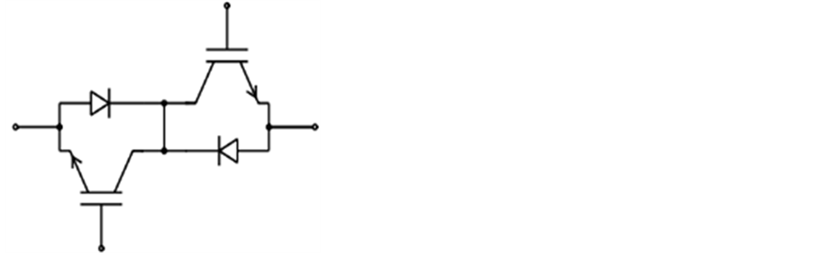
3.2. Direct Dual Matrix Converter
The dual input matrix converter is a converter, that consists of two input AC sources, nine voltage source converters (NVSC), Current source inverter, and Diode and foil capacitor. The circuit operation of Dual input matrix converter directly consists of operation AC-DC-AC because here using two input AC sources, so bidirectional switch is not possible to get an output from another direction of switch.
MC (Direct dual matrix converter) in this converter the requirement of switches are 9 in voltage source converter and three switches are required in current source inverter side and by using an direct matrix converter Voltage and current can be controlled in an single semiconducting stage (i.e.). Nine switching requirements reduce the 3 switches from the indirect matrix converter.
AC Source 1 is connected between the upper and middle switches and whereas in AC Source 2 is connected between middle and lower switches the middle switches is common between both upper and lower switches. Figure 4 shows a Dual input matrix converter.
4. Proposed Cırcuıt
4.1. Dual Input Matrix Converter (DIMC)
In the proposed dual input matrix converter, the conversion pattern takes place in two sections, first to convert AC to DC by using a nine voltage source converter (NVSC) or matrix converter section and then another conversion takes place by using an inverter to convert DC to AC. For given two input sources is not possible to give an directly AC to the grid side that’s why by using an inverter to converting DC to AC.
By using an foil capacitor and clamp circuit, the DC voltage can be stored and another on thing is the input frequency is lesser than the output frequency so the dual

Figure 4. Direct dual input matrix converter.
input matrix converter having an boosting capability and Accurate pure sinusoidal output voltage and input current and Figure 5 shows an DUAL INPUT MATRIX CONVERTER [DIMC] instead of nine voltage source converter [NVSC] and Current source inverter [CSI].
4.2. Nine Voltage Source Converter (NVSC)
Nine voltage source converter [NVSC], it consists of nine switches such as upper switching stage, middle switching stage and lower switching stage and for each stage consists of three switches and middle switches are share both the upper and lower switching stage as shown in Table 2.
4.3. Current Source Inverter (CSI)
A current source inverter accepts input from a power supply that acts as a current source rather than a voltage source. Within some limits, a DC current source delivers a set current to a load without regard to the impedance of the load or the voltage required. Most DC power sources, such as generators and batteries, are voltage sources
Table 2. Switching table for dual input matrix converter.

Figure 5. Nine voltage source converter and current source inverter.
that deliver a set voltage to the load regardless of the current drawn by the load within some limits. While a voltage source inverter produces an AC voltage by switching the input voltage to provide positive and negative voltage pulses, a current source inverter produces an AC current by switching or steering the input current to divide the current into positive and negative current pulses.
Current source inverters have been used as the inverter section of AC to AC adjustable frequency power conversion units such as those used for AC motor speed control. The control circuit contains an inner loop current regulator and an outer loop voltage or speed regulator.
5. Simulatıon Results
5.1. Subsystem of Timer Pulse Generation in NVSC
Dualinput matrix converter concept is verified by using the simulation. Figure 6 shows simulation model of dual input matrix converter used for grid. The same model can be used for different application.
5.1.1. Theoretical Calculation of Voltage (Vab) FFT Measurement in Open Loop NVSC and Closed Loop CSI
The THD value of V1 to V15 is taken from the FFT analysis of BAR relative base value in MATLAB simulation is shown in Figure 7.
 (1)
(1)
Assume the value of n = 15,
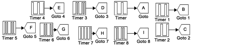
Figure 6. Timer circuit for NVSC.

Figure 7. Voltage THD level in output.
 (2)
(2)
Therefore, Total harmonic distortion (THD) = 20.25%.
5.1.2. Theoretical Calculation of Voltage (Vabc) THD
The THD value of V1 to V15 is taken from the FFT analysis of BAR relative base value in MATLAB simulation is shown in Figure 8.
 . (3)
. (3)
Assume, n = 15
 . (4)
. (4)
Therefore, Total harmonic distortion (THD) = 12.36%.
5.2. Theoretical Calculation of Voltage (Vab) FFT Measurement in Closed Loop NVSC and CSI
The THD value of V1 to V15 is taken from the FFT analysis of bar relative base value in MATLAB simulation is shown in Figure 9.

Figure 8. THD value for voltage in output side.
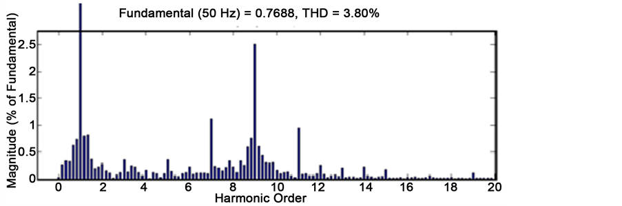
Figure 9. THD of output voltage.
 . (5)
. (5)
Assume, n = 15
 . (6)
. (6)
Therefore, Total harmonic distortion (THD) = 3.80%.
5.3. Theoretical Calculation of Current (Iab) FFT Measurement in Closed Loop NVSC and CSI
The THD value of V1 to V15 is taken from the FFT analysis of bar relative base value in MATLAB simulation is shown in Figure 10.
 . (7)
. (7)
Assume, n = 15
 . (8)
. (8)
Therefore, Total harmonic distortion (THD) = 3.51%.
6. Conclusion
The integration of two AC sources into a single grid is to reduce the size of a converter with the help of reducing switches. And in this project we are implementing with the help of MATLAB simulation and by means of an open loop and closed loop configuration in the nine-voltage source converter and current source inverter and also compensating a total harmonic distortion in higher order harmonics with no sub harmonics. And also the simulation results are shown. The control algorithms of the converter for two input AC sources are elaborated to extract commanded for two input sources to the grid. Finally this converter is very suitable to integrate two AC sources into a utility grid. The authors feel that the technology of power conversion using matrix converter topology can be extended to many other applications to approach of first building
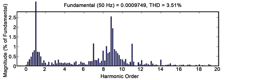
Figure 10. THD of output current.
simulation model and then building of large levels. The simulation results encourage us and we hope others to build different application for building model.
Cite this paper
Saravanan, M. and Sivakumaran, T.S. (2016) Three Phase Dual Input Direct Matrix Converter for Integra- tion of Two AC Sources from Wind Tur- bines. Circuits and Systems, 7, 3807-3817. http://dx.doi.org/10.4236/cs.2016.711318
References
- 1. Wei, L., Lipo, T.A. and Chan, H. (2002) Matrix Converter Topologies with Reduced Number of Switches. IEEE 33rd Annual Power Electronics Specialists Conference, 23-27 June 2002, 57-63.
- 2. Klumpner, C., Blaabjang, F., Boldes, L. and Nielson, P. (2006) New Modulation Method for Matrix Converter. IEEE Transactions on Industry Applications, 42, 797-806.
http://dx.doi.org/10.1109/TIA.2006.872957 - 3. Wheeler, P., Rodrigue, J., Clare, J., Empringhan, L. and Weinstein, A. (2002) Matrix Converter: Atechnology. IEEE Transactions on Industrial Electronics, 49, 276-288.
http://dx.doi.org/10.1109/41.993260 - 4. Hajabri, H., Mokhtari, H. and Chang, L. (2011) A Generalized Technique of Modeling, Analysis and Control of Matrix Converter Using SVD. IEEE Transactions on Industrial Electronics, 58, 949-959.
http://dx.doi.org/10.1109/TIE.2010.2048836 - 5. Liu, C., Wu, B., Zargari, N.R. and Xu, D. (2007) A Novel Nine Switch PWM Rectifier, Inverter Topology for the Three Phase UPS Application. Proceedings of IEEE-EPF, 1-10.
- 6. Liu, C., Wu, B., Zargari, N.R. and Xu, D. (2010) A Novel Three Phase Three Leg AC/AC Converter Using Nine Switch Converter. IEEE Transactions on Industrial Electronics, 28, 2331-2343.
- 7. Pena, R., Cardenas, R., Reyes, E., Clare, J. and Wheeler, P. (2009) A Topology for Multiple Generation System with Doubly Fed in Machine and Indirect Matrix Converter. IEEE Transactions on Industrial Electronics, 56, 4181-4193.
http://dx.doi.org/10.1109/TIE.2009.2028353