Paper Menu >>
Journal Menu >>
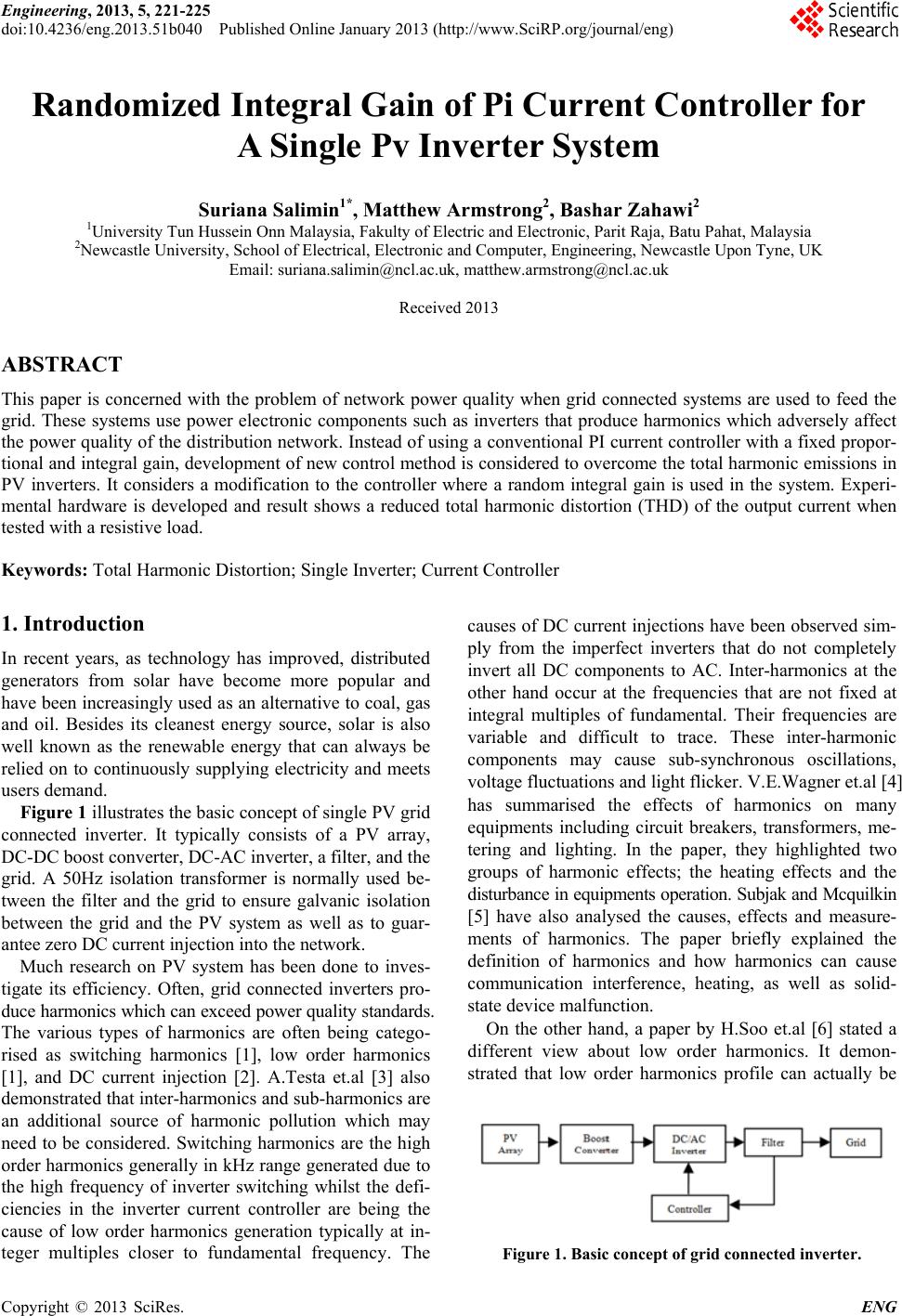 Engineering, 2013, 5, 221-225 doi:10.4236/eng.2013.51b040 Published Online January 2013 (http://www.SciRP.org/journal/eng) Copyright © 2013 SciRes. ENG Randomized Integral Gain of Pi Current Controller for A Single Pv Inverter System Suriana Salimin1*, Matthew Armstrong2, Bashar Zahawi2 1University Tun Hussein Onn Malaysia, Fakulty of Electric and Electronic, Parit Raja, Batu Pahat, Malaysia 2Newcastle University, School of Electrical, Electronic and Computer, Engineering, Newcastle Upon Tyne, UK Email: suriana.salimin@ncl.ac.uk, matthew.armstrong@ncl.ac.uk Received 2013 ABSTRACT This paper is concerned with the problem of network power quality when grid connected systems are used to feed the grid. These systems use power electronic components such as inverters that produce harmonics which adversely affect the power quality of the distribution network. Instead of using a conventional PI current controller with a fixed propor- tional and integral gain, development of new control method is considered to overcome the total harmonic emissions in PV inverters. It considers a modification to the controller where a random integral gain is used in the system. Experi- mental hardware is developed and result shows a reduced total harmonic distortion (THD) of the output current when tested with a resistive load. Keywords: Total Harmonic Distortion; Single Inverter; Current Controller 1. Introduction In recent years, as technology has improved, distributed generators from solar have become more popular and have been increasingly used as an alternative to coal, gas and oil. Besides its cleanest energy source, solar is also well known as the renewable energy that can always be relied on to continuously supplying electricity and meets users demand. Figure 1 illustrates the basic concept of single PV grid connected inverter. It typically consists of a PV array, DC-DC boost converter, DC-AC inverter, a filter, and the grid. A 50Hz isolation transformer is normally used be- tween the filter and the grid to ensure galvanic isolation between the grid and the PV system as well as to guar- antee zero DC current injection into the network. Much research on PV system has been done to inves- tigate its efficiency. Often, grid connected inverters pro- duce harmonics which can exceed power quality standards. The various types of harmonics are often being catego- rised as switching harmonics [1], low order harmonics [1], and DC current injection [2]. A.Testa et.al [3] also demonstrated that inter-harmonics and sub-harmonics are an additional source of harmonic pollution which may need to be considered. Switching harmonics are the high order harmonics generally in kHz range generated due to the high frequency of inverter switching whilst the defi- ciencies in the inverter current controller are being the cause of low order harmonics generation typically at in- teger multiples closer to fundamental frequency. The causes of DC current injections have been observed sim- ply from the imperfect inverters that do not completely invert all DC components to AC. Inter-harmonics at the other hand occur at the frequencies that are not fixed at integral multiples of fundamental. Their frequencies are variable and difficult to trace. These inter-harmonic components may cause sub-synchronous oscillations, voltage fluctuations and light flicker. V.E.Wagner et.al [4] has summarised the effects of harmonics on many equipments including circuit breakers, transformers, me- tering and lighting. In the paper, they highlighted two groups of harmonic effects; the heating effects and the disturbance in equipments operation. Subjak and Mcquilkin [5] have also analysed the causes, effects and measure- ments of harmonics. The paper briefly explained the definition of harmonics and how harmonics can cause communication interference, heating, as well as solid- state device malfunction. On the other hand, a paper by H.Soo et.al [6] stated a different view about low order harmonics. It demon- strated that low order harmonics profile can actually be Figure 1. Basic concept of grid connected inverter. 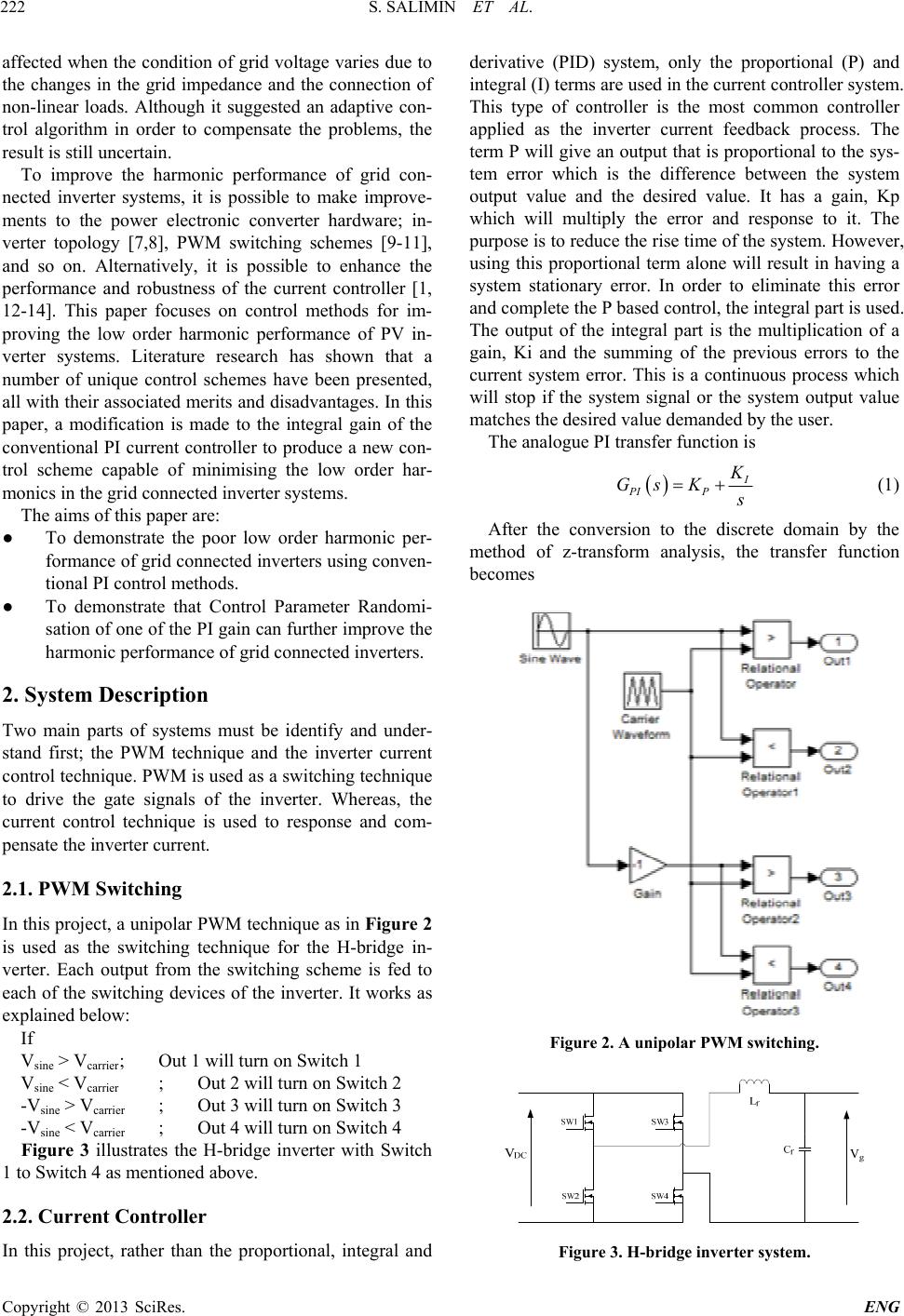 S. SALIMIN ET AL. Copyright © 2013 SciRes. ENG 222 affected when the condition of grid voltage varies due to the changes in the grid impedance and the connection of non-linear loads. Although it suggested an adaptive con- trol algorithm in order to compensate the problems, the result is still uncertain. To improve the harmonic performance of grid con- nected inverter systems, it is possible to make improve- ments to the power electronic converter hardware; in- verter topology [7,8], PWM switching schemes [9-11], and so on. Alternatively, it is possible to enhance the performance and robustness of the current controller [1, 12-14]. This paper focuses on control methods for im- proving the low order harmonic performance of PV in- verter systems. Literature research has shown that a number of unique control schemes have been presented, all with their associated merits and disadvantages. In this paper, a modification is made to the integral gain of the conventional PI current controller to produce a new con- trol scheme capable of minimising the low order har- monics in the grid connected inverter systems. The aims of this paper are: ● To demonstrate the poor low order harmonic per- formance of grid connected inverters using conven- tional PI control methods. ● To demonstrate that Control Parameter Randomi- sation of one of the PI gain can further improve the harmonic performance of grid connected inverters. 2. System Description Two main parts of systems must be identify and under- stand first; the PWM technique and the inverter current control technique. PWM is used as a switching technique to drive the gate signals of the inverter. Whereas, the current control technique is used to response and com- pensate the inverter current. 2.1. PWM Switching In this project, a unipolar PWM technique as in Figure 2 is used as the switching technique for the H-bridge in- verter. Each output from the switching scheme is fed to each of the switching devices of the inverter. It works as explained below: If Vsine > Vcarrier ; Out 1 will turn on Switch 1 Vsine < Vcarrier ; Out 2 will turn on Switch 2 -Vsine > Vcarrier ; Out 3 will turn on Switch 3 -Vsine < Vcarrier ; Out 4 will turn on Switch 4 Figure 3 illustrates the H-bridge inverter with Switch 1 to Switch 4 as mentioned above. 2.2. Current Controller In this project, rather than the proportional, integral and derivative (PID) system, only the proportional (P) and integral (I) terms are used in the current controller system. This type of controller is the most common controller applied as the inverter current feedback process. The term P will give an output that is proportional to the sys- tem error which is the difference between the system output value and the desired value. It has a gain, Kp which will multiply the error and response to it. The purpose is to reduce the rise time of the system. However, using this proportional term alone will result in having a system stationary error. In order to eliminate this error and complete the P based control, the integral part is used. The output of the integral part is the multiplication of a gain, Ki and the summing of the previous errors to the current system error. This is a continuous process which will stop if the system signal or the system output value matches the desired value demanded by the user. The analogue PI transfer function is I PI P K Gs K s (1) After the conversion to the discrete domain by the method of z-transform analysis, the transfer function becomes Figure 2. A unipolar PWM switching. Figure 3. H-bridge inverter system. 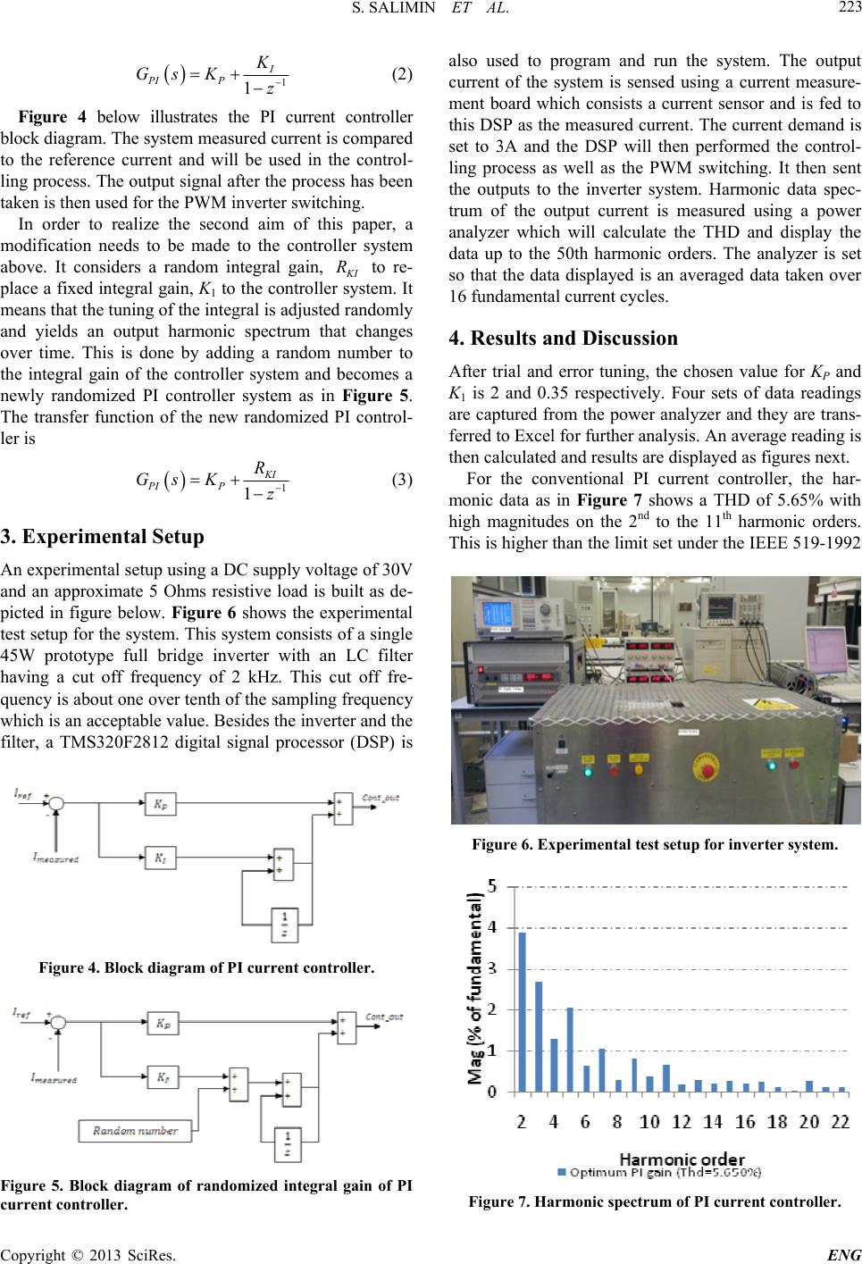 S. SALIMIN ET AL. Copyright © 2013 SciRes. ENG 223 1 1 I PI P K Gs Kz (2) Figure 4 below illustrates the PI current controller block diagram. The system measured current is compared to the reference current and will be used in the control- ling process. The output signal after the process has been taken is then used for the PWM inverter switching. In order to realize the second aim of this paper, a modification needs to be made to the controller system above. It considers a random integral gain, K I R to re- place a fixed integral gain, K1 to the controller system. It means that the tuning of the integral is adjusted randomly and yields an output harmonic spectrum that changes over time. This is done by adding a random number to the integral gain of the controller system and becomes a newly randomized PI controller system as in Figure 5. The transfer function of the new randomized PI control- ler is 1 1 KI PIP R Gs Kz (3) 3. Experimental Setup An experimental setup using a DC supply voltage of 30V and an approximate 5 Ohms resistive load is built as de- picted in figure below. Figure 6 shows the experimental test setup for the system. This system consists of a single 45W prototype full bridge inverter with an LC filter having a cut off frequency of 2 kHz. This cut off fre- quency is about one over tenth of the sampling frequency which is an acceptable value. Besides the inverter and the filter, a TMS320F2812 digital signal processor (DSP) is Figure 4. Block diagram of PI current controller. Figure 5. Block diagram of randomized integral gain of PI current con t r o ller. also used to program and run the system. The output current of the system is sensed using a current measure- ment board which consists a current sensor and is fed to this DSP as the measured current. The current demand is set to 3A and the DSP will then performed the control- ling process as well as the PWM switching. It then sent the outputs to the inverter system. Harmonic data spec- trum of the output current is measured using a power analyzer which will calculate the THD and display the data up to the 50th harmonic orders. The analyzer is set so that the data displayed is an averaged data taken over 16 fundamental current cycles. 4. Results and Discussion After trial and error tuning, the chosen value for KP and K1 is 2 and 0.35 respectively. Four sets of data readings are captured from the power analyzer and they are trans- ferred to Excel for further analysis. An average reading is then calculated and results are displayed as figures next. For the conventional PI current controller, the har- monic data as in Figure 7 shows a THD of 5.65% with high magnitudes on the 2nd to the 11th harmonic orders. This is higher than the limit set under the IEEE 519-1992 Figure 6. Experimental test setup for inverter system. Figure 7. Harmonic spectrum of PI current controller. 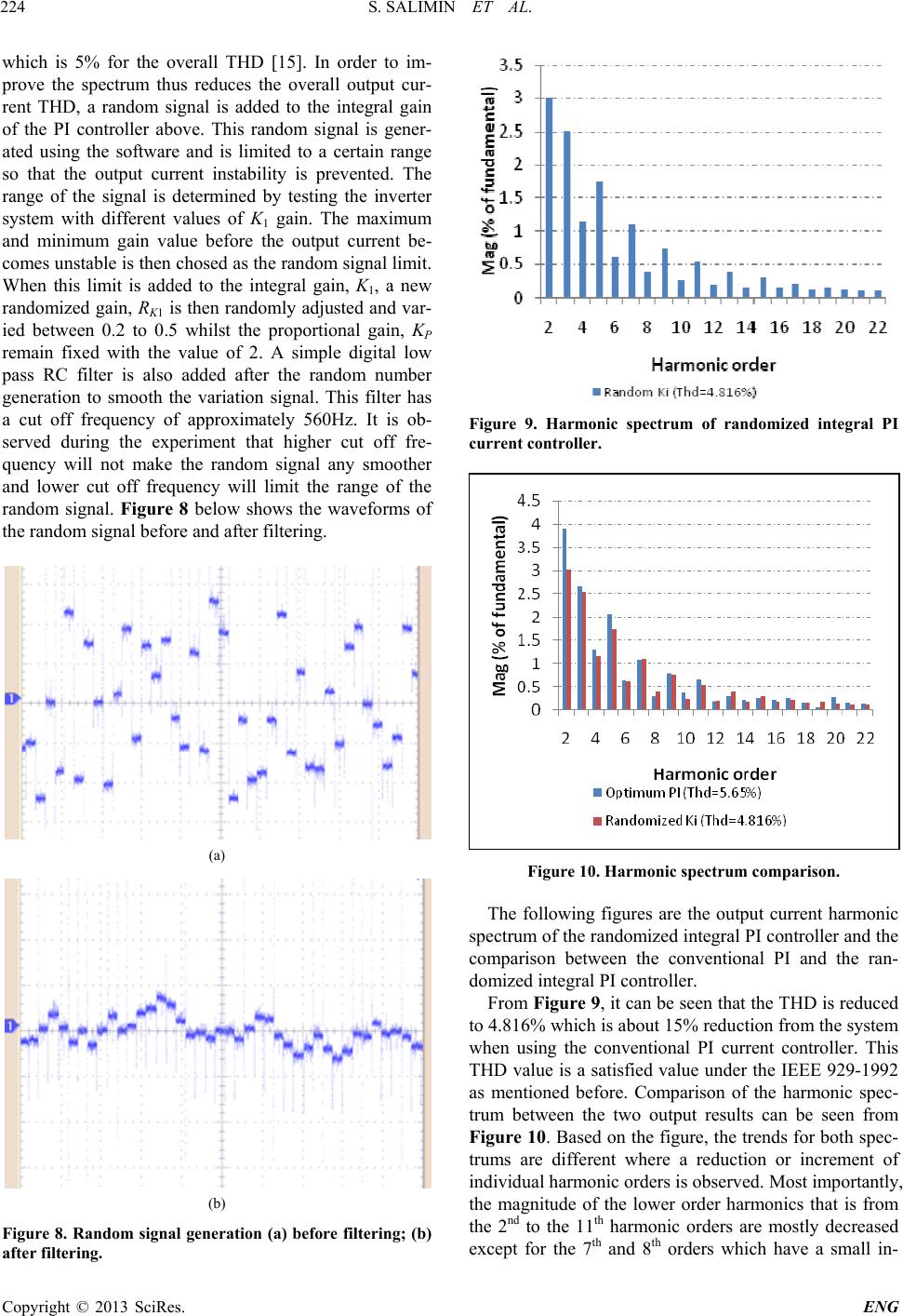 S. SALIMIN ET AL. Copyright © 2013 SciRes. ENG 224 which is 5% for the overall THD [15]. In order to im- prove the spectrum thus reduces the overall output cur- rent THD, a random signal is added to the integral gain of the PI controller above. This random signal is gener- ated using the software and is limited to a certain range so that the output current instability is prevented. The range of the signal is determined by testing the inverter system with different values of K1 gain. The maximum and minimum gain value before the output current be- comes unstable is then chosed as the random signal limit. When this limit is added to the integral gain, K1, a new randomized gain, RK1 is then randomly adjusted and var- ied between 0.2 to 0.5 whilst the proportional gain, KP remain fixed with the value of 2. A simple digital low pass RC filter is also added after the random number generation to smooth the variation signal. This filter has a cut off frequency of approximately 560Hz. It is ob- served during the experiment that higher cut off fre- quency will not make the random signal any smoother and lower cut off frequency will limit the range of the random signal. Figure 8 below shows the waveforms of the random signal before and after filtering. (a) (b) Figure 8. Random signal generation (a) before filtering; (b) after filteri ng. Figure 9. Harmonic spectrum of randomized integral PI current con t r o ller. Figure 10. Harmonic spectrum comparison. The following figures are the output current harmonic spectrum of the randomized integral PI controller and the comparison between the conventional PI and the ran- domized integral PI controller. From Figure 9, it can be seen that the THD is reduced to 4.816% which is about 15% reduction from the system when using the conventional PI current controller. This THD value is a satisfied value under the IEEE 929-1992 as mentioned before. Comparison of the harmonic spec- trum between the two output results can be seen from Figure 10. Based on the figure, the trends for both spec- trums are different where a reduction or increment of individual harmonic orders is observed. Most importantly, the magnitude of the lower order harmonics that is from the 2nd to the 11th harmonic orders are mostly decreased except for the 7th and 8th orders which have a small in-  S. SALIMIN ET AL. Copyright © 2013 SciRes. ENG 225 crement. Harmonic orders beyond the 11th show a fair reduction as well as increment. This behaviour of having a reduction and increment in harmonic orders magnitude yields to the reduction of the Total Harmonic Distortion (THD) of inverter system when using the proposed method. 5. Conclusions This paper has proposed a modified PI current controller to overcome the issue of higher THD in a single inverter system when using the conventional PI current controller. This modification includes the integral gain, K1 of the PI controller to be adjusted automatically using the ran- domized integral gain, RK1 whilst the proportional gain, KP of the controller remain the same. Experimental re- sults show an improved THD performance by 15% com- pared to the system when using the conventional PI method. With no further components are required in or- der to implement the proposed method, the total cost of the PV inverter system remains unchanged. 6. Acknowledgements This project is part of the principle author`s research project to complete her PhD study in Newcastle Univer- sity, UK. She would like to show her gratitude to Uni- versity Tun Hussein Onn Malaysia for the sponsorship during the study. REFERENCES [1] M. Armstrong, D. J. Atkinson, C. M. Johnson, and T. D. Abeyasekera, "Low order harmonic cancellation in a grid connected multiple inverter system via current control parameter randomization," IEEE Transactions on Power Electronics, vol. 20, pp. 885-892, 2005. [2] M. Armstrong, D. J. Atkinson, C. M. Johnson, and T. D. Abeyasekera, "Auto-calibrating dc link current sensing technique for transformerless, grid connected, H-bridge inverter systems," IEEE Transactions on Power Elec- tronics, vol. 21, pp. 1385-1393, 2006. [3] A. Testa, M. F. Akram, R. Burch, G. Carpinelli, G. Chang, V. Dinavahi, C. Hatziadoniu, W. M. Grady, E. Gunther, M. Halpin, P. Lehn, Y. Liu, R. Langella, M. Lowenstein, A. Medina, T. Ortmeyer, S. Ranade, P. Ribeiro, N. Wat- son, J. Wikston, and W. Xu, "Interharmonics: Theory and Modeling," Power Delivery, IEEE Transactions on, vol. 22, pp. 2335-2348, 2007. [4] V. E. Wagner, J. C. Balda, D. C. Griffith, A. McEachern, T. M. Barnes, D. P. Hartmann, D. J. Phileggi, A. E. Emannuel, W. F. Horton, W. E. Reid, R. J. Ferraro, and W. T. Jewell, "Effects of harmonics on equipment," Power Delivery, IEEE Transactions on, vol. 8, pp. 672-680, 1993. [5] J. S. Subjak, Jr. and J. S. McQuilkin, "Harmonics-causes, effects, measurements, and analysis: an update," Industry Applications, IEEE Transactions on, vol. 26, pp. 1034-1042, 1990. [6] G. Hong Soo, M. Armstrong, and B. Zahawi, "The effect of grid operating conditions on the current controller per- formance of grid connected photovoltaic inverters," in Power Electronics and Applications, 2009. EPE '09. 13th European Conference on, 2009, pp. 1-8. [7] J. Selvaraj and N. A. Rahim, "Multilevel Inverter For Grid-Connected PV System Employing Digital PI Con- troller," Industrial Electronics, IEEE Transactions on, vol. 56, pp. 149-158, 2009. [8] M. Katiamoorthy, R. M. Sekar, and G. C. Raj, "A new single-phase PV fed five-level inverter topology con- nected to the grid," in Communication Control and Com- puting Technologies (ICCCCT), 2010 IEEE International Conference on, 2010, pp. 196-203. [9] R. A. Villarreal-Ortiz, M. Hernandez-Angeles, C. R. Fuerte-Esquivel, and R. O. Villanueva-Chavez, "Centroid PWM technique for inverter harmonics elimination," Power Delivery, IEEE Transactions on, vol. 20, pp. 1209-1210, 2005. [10] L. G. Franquelo, J. Napoles, R. C. P. Guisado, J. I. Leon, and M. A. Aguirre, "A Flexible Selective Harmonic Mitigation Technique to Meet Grid Codes in Three-Level PWM Converters," Industrial Electronics, IEEE Transac- tions on, vol. 54, pp. 3022-3029, 2007. [11] M. A. A. Younis, N. A. Rahim, and S. Mekhilef, "High efficiency THIPWM three-phase inverter for grid con- nected system," in Industrial Electronics & Applications (ISIEA), 2010 IEEE Symposium on, 2010, pp. 88-93. [12] H. Qunhai, K. Li, W. Tongzhen, Z. Guowei, and K. Lingzhi, "A new method for the photovoltaic grid-connected inverter control," in Electric Utility De- regulation and Restructuring and Power Technologies, 2008. DRPT 2008. Third International Conference on, 2008, pp. 2626-2629. [13] M. Castilla, J. Miret, J. Matas, L. G. de Vicua, and J. M. Guerrero, "Linear Current Control Scheme With Series Resonant Harmonic Compensator for Single-Phase Grid-Connected Photovoltaic Inverters," Industrial Elec- tronics, IEEE Transactions on, vol. 55, pp. 2724-2733, 2008. [14] R. Teodorescu, F. Blaabjerg, U. Borup, and M. Liserre, "A new control structure for grid-connected LCL PV in- verters with zero steady-state error and selective har- monic compensation," in Applied Power Electronics Conference and Exposition, 2004. APEC '04. Nineteenth Annual IEEE, 2004, pp. 580-586 Vol.1. [15] "IEEE Recommended Practices and Requirements for Harmonic Control in Electrical Power Systems," IEEE Std 519-1992, p. 0_1, 1993. |