Paper Menu >>
Journal Menu >>
 Journal of Minerals & Materials Characterization & Engineering, Vol. 9, No.8, pp.671-681, 2010 jmmce.org Printed in the USA. All rights reserved 671 Studies on Mechanical Characterization of Polyprop yl en e/ Na+-MMT Nanocomposites V. Selvakumara,*, K. Palanikumarb, K. Palaniveluc aSathyabama University, Chennai-119. bSri Sai Ram Institute of Technology, Chennai. cCentral Institute of Plastics Engineering & Technology, Chennai. *Corresponding author: vselvakumar75@yahoo.in ABSTRACT This article addresses the effect of montmorillonite (MMT) on the morphology, and mechanical properties of polypropylene (PP). PP/MMT nanocomposites have been prepared by melt mixing using maleic anhydride grafted polypropylene (MAH-g-PP) as compatibilizing agents. Melt mixing was achieved using twin screw extruder. The MAH-g-PP used as compatibilizer helped the dispersion of the MMT in PP matrix. The influence of MMT on the impact fracture morphology of the nanocomposites was studied by scanning electron microscopy (SEM). The polymer composites were characterized by using different techniques such as X-ray diffraction (XRD), tranmission electron microscopy (TEM) and mechanical characterization as per ASTM standards. The mechanical properties of strength and modulus of the nanocomposites increases with addition of 5 wt% of nanoclay and impact strength and hardness of the nanocomposites increses with addition of 3 wt% of nanoclay. Keywords: Polypropylene; Montmorillonite; X-ray diffraction (XRD); scanning electron microscopy (SEM);Tranmission electron microscopy (TEM). 1. INTRODUCTION Polypropylene is one of the fastest growing classes of thermoplastics. This growth is attributed to its attractive combination of low cost, low density, and high heat distortion temperature (HDT). Currently, automotive and appliance applications employ glass or mineral-filled systems with loading levels ranging from 15 to 50 wt%. This approach improves most mechanical properties, 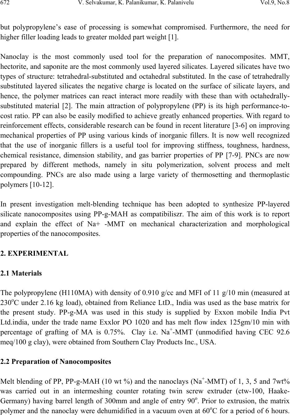 672 V. Selvakumar, K. Palanikumar, K. Palanivelu Vol.9, No.8 but polypropylene’s ease of processing is somewhat compromised. Furthermore, the need for higher filler loading leads to greater molded part weight [1]. Nanoclay is the most commonly used tool for the preparation of nanocomposites. MMT, hectorite, and saponite are the most commonly used layered silicates. Layered silicates have two types of structure: tetrahedral-substituted and octahedral substituted. In the case of tetrahedrally substituted layered silicates the negative charge is located on the surface of silicate layers, and hence, the polymer matrices can react interact more readily with these than with octahedrally- substituted material [2]. The main attraction of polypropylene (PP) is its high performance-to- cost ratio. PP can also be easily modified to achieve greatly enhanced properties. With regard to reinforcement effects, considerable research can be found in recent literature [3-6] on improving mechanical properties of PP using various kinds of inorganic fillers. It is now well recognized that the use of inorganic fillers is a useful tool for improving stiffness, toughness, hardness, chemical resistance, dimension stability, and gas barrier properties of PP [7-9]. PNCs are now prepared by different methods, namely in situ polymerization, solvent process and melt compounding. PNCs are also made using a large variety of thermosetting and thermoplastic polymers [10-12]. In present investigation melt-blending technique has been adopted to synthesize PP-layered silicate nanocomposites using PP-g-MAH as compatibiliszr. The aim of this work is to report and explain the effect of Na+ -MMT on mechanical characterization and morphological properties of the nanocomposites. 2. EXPERIMENTAL 2.1 Materials The polypropylene (H110MA) with density of 0.910 g/cc and MFI of 11 g/10 min (measured at 230oC under 2.16 kg load), obtained from Reliance LtD., India was used as the base matrix for the present study. PP-g-MA was used in this study is supplied by Exxon mobile India Pvt Ltd.india, under the trade name Exxlor PO 1020 and has melt flow index 125gm/10 min with percentage of grafting of MA is 0.75%. Clay i.e. Na+-MMT (unmodified having CEC 92.6 meq/100 g clay), were obtained from Southern Clay Products Inc., USA. 2.2 Preparation of Nanocomposites Melt blending of PP, PP-g-MAH (10 wt %) and the nanoclays (Na+-MMT) of 1, 3, 5 and 7wt% was carried out in an intermeshing counter rotating twin screw extruder (ctw-100, Haake- Germany) having barrel length of 300mm and angle of entry 90o. Prior to extrusion, the matrix polymer and the nanoclay were dehumidified in a vacuum oven at 60oC for a period of 6 hours.  Vol.9, No.8 Studies on Mechanical Characterization 673 PP was fed at the rate of 5 kg/hour and the nanoclay was subsequently introduced at the melting zone. The process was carried out at a screw speed of 150 rpm and a temperature difference of 160, 170 and 180oC between feed zones to die zone, followed by granulation in a pelletizer (Fission, Germany) and drying. These granules were further injection molded using injection moulding machine (SP 130 Windsor Clocknar Ltd) having clamping force 800kN fitted with a dehumidifier at a temperature range of 195–220oC and mold temperature of 80oC, for preparation of test specimens of tensile, flexural and impact strength as per ASTMD. 2.3 Characterization 2.3.1 Mechanical characterization Specimens of virgin PP and PP/nanocomposites of dimensions 165X13X3 mm were subjected to tensile test as per ASTM D-638 using universal testing machine (UTM) LR-100K (Lloyd Instrument Ltd U.K). A cross head speed of 50mm/min and gauge length of 50mm was used for carrying out the test. Specimens of virgin PP and PP/Nanocomposites of dimensions 80X12.7X3 mm were taken for flexural test under three point bending using the same universal testing machine accordance with ASTM-D 790 at a cross head speed of 1.3 mm/min and a span length of 50mm.Similarly,Izod impact strength was determined from the specimens having dimensions 63.5X12.7X3mm with a “V” notch depth of 2.54 mm and notch angle of 45o as per ASTM-D 256 using impact meter 6545(Ceast.Italy).For analyzing the mechanical properties test specimens were initially conditioned at 23+1o C and 55+2% RH. Five replicate specimens were used for each test and the data reported are the average of five tests. Corresponding standard deviations along with measurement uncertainty values for the experimental data showing the maximum standard deviation is also included. 2.3.2 Scanning electron microscopy The morphology of the impact fractured surfaces of neat PP and its nanocomposites, the fracture surfaces were coated with thin layers of gold of about 10 A. All specimens were examined with JEOL, JSM 840A scanning electron microscope with an accelerating of 10kv. 2.3.3 Wide angle X-Ray diffraction (WAXD) Wide angle X-ray scans (WAXS) were made using a Philips X’Pert MPD (Japan) X-ray diffractometer in the reflection mode which had a graphite monochromator and a Cu Ka radiation source (k ¼ 1.54A˚) at a scan rate of 0.5o/min over the range of 2h ¼ 1–10o . X-ray analyses were performed at room temperature on as molded specimens. Both for the clays and the nanocomposites, XRD was recorded using, operated at 40Kv and 30mA.The basal spacing or d001reflection of the samples was calculated from Bragg’s equation by monitoring the 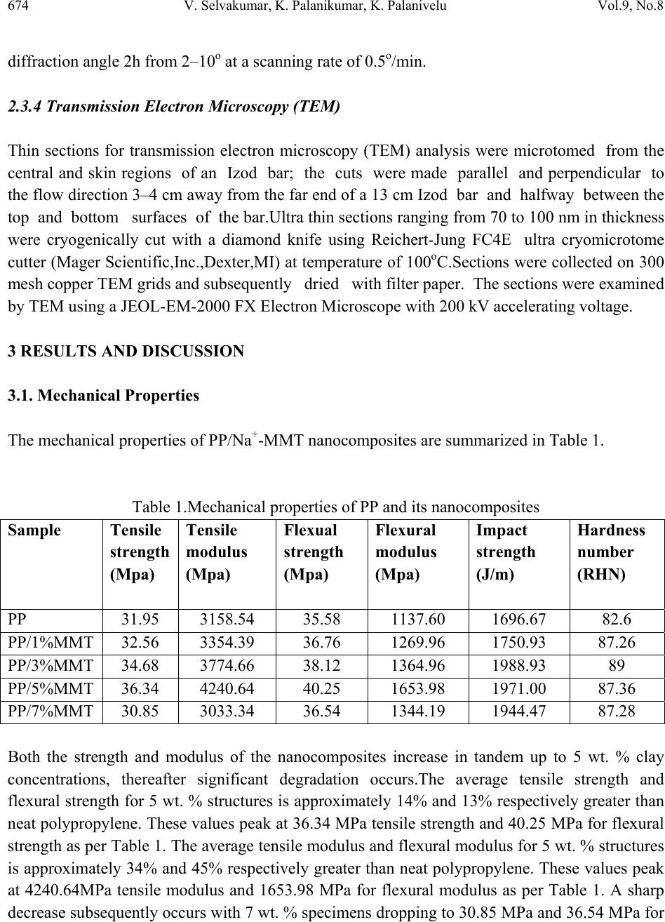 674 V. Selvakumar, K. Palanikumar, K. Palanivelu Vol.9, No.8 diffraction angle 2h from 2–10o at a scanning rate of 0.5o/min. 2.3.4 Transmission Electron Microscopy (TEM) Thin sections for transmission electron microscopy (TEM) analysis were microtomed from the central and skin regions of an Izod bar; the cuts were made parallel and perpendicular to the flow direction 3–4 cm away from the far end of a 13 cm Izod bar and halfway between the top and bottom surfaces of the bar.Ultra thin sections ranging from 70 to 100 nm in thickness were cryogenically cut with a diamond knife using Reichert-Jung FC4E ultra cryomicrotome cutter (Mager Scientific,Inc.,Dexter,MI) at temperature of 100oC.Sections were collected on 300 mesh copper TEM grids and subsequently dried with filter paper. The sections were examined by TEM using a JEOL-EM-2000 FX Electron Microscope with 200 kV accelerating voltage. 3 RESULTS AND DISCUSSION 3.1. Mechanical Properties The mechanical properties of PP/Na+-MMT nanocomposites are summarized in Table 1. Table 1.Mechanical properties of PP and its nanocomposites Sample Tensile strength (Mpa) Tensile modulus (Mpa) Flexual strength (Mpa) Flexural modulus (Mpa) Impact strength (J/m) Hardness number (RHN) PP 31.95 3158.54 35.58 1137.60 1696.67 82.6 PP/1%MMT 32.56 3354.39 36.76 1269.96 1750.93 87.26 PP/3%MMT 34.68 3774.66 38.12 1364.96 1988.93 89 PP/5%MMT 36.34 4240.64 40.25 1653.98 1971.00 87.36 PP/7%MMT 30.85 3033.34 36.54 1344.19 1944.47 87.28 Both the strength and modulus of the nanocomposites increase in tandem up to 5 wt. % clay concentrations, thereafter significant degradation occurs.The average tensile strength and flexural strength for 5 wt. % structures is approximately 14% and 13% respectively greater than neat polypropylene. These values peak at 36.34 MPa tensile strength and 40.25 MPa for flexural strength as per Table 1. The average tensile modulus and flexural modulus for 5 wt. % structures is approximately 34% and 45% respectively greater than neat polypropylene. These values peak at 4240.64MPa tensile modulus and 1653.98 MPa for flexural modulus as per Table 1. A sharp decrease subsequently occurs with 7 wt. % specimens dropping to 30.85 MPa and 36.54 MPa for  Vol.9, No.8 Studies on Mechanical Characterization 675 the strength respectively shown is Figure 1. A similar trend for the modulus of the nanocomposites is shown in Figure 2. Fig 1: Strength of PP/MMT nanocomposites Fig 2: Modulus of PP/MMT nanocomposites 0 1 2 3 4 5 6 7 0 10 20 30 40 Te nsile strength Flexural strength Strength (MPa) % of Nanoclay 0 1 2 3 4 5 6 7 0 1000 2000 3000 4000 5000 Flexural m odulus Tensile modulus Modulus (MPa) % of Nanoclay  676 V. Selvakumar, K. Palanikumar, K. Palanivelu Vol.9, No.8 As a result, the strength and the modulus of the PP nanocomposites increase with MMT loadings. A fraction of intercalated structure decreases with increasing nanoclay content. At higher clay concentrations, aggregation of the nanoclays may occur decreasing the strength. The increased mechanical properties at low concentration of nanoclays may be due to the uniformly dispersed MMT tactoid and intercalated structures of the nanocomposites shown in TEM and X- RD analysis. The increase in both hardness and impact strength for a nanoclay loading up to 3 wt. % is by the formation of intercalated and exfoliated nanoclay structures shown in the TEM analysis. Figure 3 shows an increase in both the impact strength as well as the Vickers hardness number up to 3 wt. % loading. Fig 3: Impact strength and Rockwell hardness number of PP/MMT nanocomposites 3.2 X-Ray Diffraction Figure 4 shows the X-ray diffraction patterns of MMT silicate. As shown in this figure, the peak maximum shifts from 2θ = 6.98°, corresponding to basal spacing d001 of 12.6 Ao.The XRD pattern of polypropylene infused with 1, 3, 5, and 7 wt. % MMT is shown in Figure 5. During mixing, the polymer infuses and intercalates between the intergallery spacing of layered silicates and makes the clay layers to move apart. The disappearance of peak indicates the separation of clay layers and the formation of nanocomposites at 1 wt. % to 5 wt. % clay loadings. This is confirmed by TEM studies indicating that predominantly exfoliated nanoclay structures have formed in 1 wt. % and 3 wt. % nanoclay polypropylene specimens. Polypropylene infused with 5 wt. % nanoclays has more intercalated clay structures. -1012345678 1700 1750 1800 1850 1900 1950 2000 Im pact strength Hardness num ber % of N anoclay Impact strength (J/m) 82 84 86 88 90 Rockwell hardness numb er (RHN) 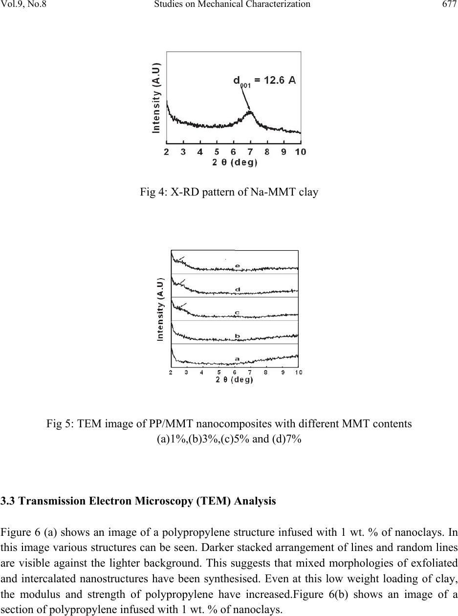 Vol.9, No.8 Studies on Mechanical Characterization 677 Fig 4: X-RD pattern of Na-MMT clay Fig 5: TEM image of PP/MMT nanocomposites with different MMT contents (a)1%,(b)3%,(c)5% and (d)7% 3.3 Transmission Electron Microscopy (TEM) Analysis Figure 6 (a) shows an image of a polypropylene structure infused with 1 wt. % of nanoclays. In this image various structures can be seen. Darker stacked arrangement of lines and random lines are visible against the lighter background. This suggests that mixed morphologies of exfoliated and intercalated nanostructures have been synthesised. Even at this low weight loading of clay, the modulus and strength of polypropylene have increased.Figure 6(b) shows an image of a section of polypropylene infused with 1 wt. % of nanoclays. 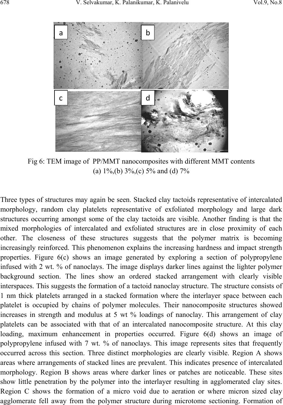 678 V. Selvakumar, K. Palanikumar, K. Palanivelu Vol.9, No.8 Fig 6: TEM image of PP/MMT nanocomposites with different MMT contents (a) 1%,(b) 3%,(c) 5% and (d) 7% Three types of structures may again be seen. Stacked clay tactoids representative of intercalated morphology, random clay platelets representative of exfoliated morphology and large dark structures occurring amongst some of the clay tactoids are visible. Another finding is that the mixed morphologies of intercalated and exfoliated structures are in close proximity of each other. The closeness of these structures suggests that the polymer matrix is becoming increasingly reinforced. This phenomenon explains the increasing hardness and impact strength properties. Figure 6(c) shows an image generated by exploring a section of polypropylene infused with 2 wt. % of nanoclays. The image displays darker lines against the lighter polymer background section. The lines show an ordered stacked arrangement with clearly visible interspaces. This suggests the formation of a tactoid nanoclay structure. The structure consists of 1 nm thick platelets arranged in a stacked formation where the interlayer space between each platelet is occupied by chains of polymer molecules. Their nanocomposite structures showed increases in strength and modulus at 5 wt % loadings of nanoclay. This arrangement of clay platelets can be associated with that of an intercalated nanocomposite structure. At this clay loading, maximum enhancement in properties occurred. Figure 6(d) shows an image of polypropylene infused with 7 wt. % of nanoclays. This image represents sites that frequently occurred across this section. Three distinct morphologies are clearly visible. Region A shows areas where arrangements of stacked lines are prevalent. This indicates presence of intercalated morphology. Region B shows areas where darker lines or patches are noticeable. These sites show little penetration by the polymer into the interlayer resulting in agglomerated clay sites. Region C shows the formation of a micro void due to aeration or where micron sized clay agglomerate fell away from the polymer structure during microtome sectioning. Formation of ab cd  Vol.9, No.8 Studies on Mechanical Characterization 679 micro voids and clay agglomerates may be the cause for degraded mechanical properties at this clay loading. 3.4 Scanning Electron Microscopy (SEM) Analysis Figure 7 shows the impact fractured surface of PP and its nanocomposites.From Figure 7(a) the surface shows a fairly homogenous polymer with minimal high stress zones. The high stress zones depicted by the impact fracured hole size is large and number of holes are less.In Figure 7(b, c and d) arrows indicate there is a distinct change in the fractured surface when compared to PP sample.The impact fractured hole size is small and number of holes are more. These structures show several high stress zones which indicate the increased reinforcement of the polymer matrix and good dispersion of the nanoclay in nanocomposites. It is finer and more particulate in nature. Fig 7: SEM image of PP and PP/MMT nanocomposites with different MMT contents (a) PP,(b) 1%,(c) 3%,(d) 5% and (e) 7% ab cd e 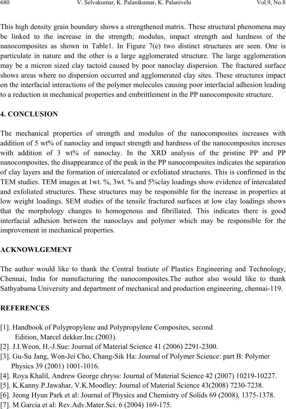 680 V. Selvakumar, K. Palanikumar, K. Palanivelu Vol.9, No.8 This high density grain boundary shows a strengthened matrix. These structural phenomena may be linked to the increase in the strength; modulus, impact strength and hardness of the nanocomposites as shown in Table1. In Figure 7(e) two distinct structures are seen. One is particulate in nature and the other is a large agglomerated structure. The large agglomeration may be a micron sized clay tactoid caused by poor nanoclay dispersion. The fractured surface shows areas where no dispersion occurred and agglomerated clay sites. These structures impact on the interfacial interactions of the polymer molecules causing poor interfacial adhesion leading to a reduction in mechanical properties and embrittlement in the PP nanocomposite structure. 4. CONCLUSION The mechanical properties of strength and modulus of the nanocomposites increases with addition of 5 wt% of nanoclay and impact strength and hardness of the nanocomposites increses with addition of 3 wt% of nanoclay. In the XRD analysis of the pristine PP and PP nanocomposites, the disappearance of the peak in the PP nanocomposites indicates the separation of clay layers and the formation of intercalated or exfoliated structures. This is confirmed in the TEM studies. TEM images at 1wt. %, 3wt. % and 5%clay loadings show evidence of intercalated and exfoliated structures. These structures may be responsible for the increase in properties at low weight loadings. SEM studies of the tensile fractured surfaces at low clay loadings shows that the morphology changes to homogenous and fibrillated. This indicates there is good interfacial adhesion between the nanoclays and polymer which may be responsible for the improvement in mechanical properties. ACKNOWLGEMENT The author would like to thank the Central Instiute of Plastics Engineering and Technology, Chennai, India for manufacturing the nanocomposites.The author also would like to thank Sathyabama University and department of mechanical and production engineering, chennai-119. REFERENCES [1]. Handbook of Polypropylene and Polypropylene Composites, second Edition, Marcel dekker.Inc.(2003). [2]. J.I.Weon, H.-J.Sue: Journal of Material Science 41 (2006) 2291-2300. [3]. Gu-Su Jang, Won-Jei Cho, Chang-Sik Ha: Journal of Polymer Science: part B: Polymer Physics 39 (2001) 1001-1016. [4]. Roya Khalil, Andrew George chryss: Journal of Material Science 42 (2007) 10219-10227. [5]. K.Kanny.P.Jawahar, V.K.Moodley: Journal of Material Science 43(2008) 7230-7238. [6]. Jeong Hyun Park et al: Journal of Physics and Chemistry of Solids 69 (2008), 1375-1378. [7]. M.Garcia et al: Rev.Adv.Mater.Sci. 6 (2004) 169-175.  Vol.9, No.8 Studies on Mechanical Characterization 681 [8]. Xiaohui Liu, Qiuju Wu: Polymer 42 (2001) 10013-10019 [9]. Ludovic cauvin et al: C.R.Mecanique 335 (2007) 702-707. [10]. D.Garcia-lopez et al: Polymer Bulletin, 59 (2007) 667-676. [11]. T.C.Chung: Journal of Organ Metallic Chemistry 690 (2005) 6292-6199. [12]. Laszlo Szazdi et al: Polymer, 46(2005) 8001-8010. |