Materials Sciences and Applications
Vol.09 No.03(2018), Article ID:83349,15 pages
10.4236/msa.2018.93022
Modification in Cu-Zn Alloy Properties by 2 MeV Ni+ Ions Irradiation
Shahbaz Ahmad1,2*, Shazia Bashir2, Daniel Yousaf2, Mian Ahsan Ali2
1Department of Physics, University of Sargodha, Lahore Campus, Lahore, Pakistan
2Center for Advanced Studies in Physics, Government College University, Lahore, Pakistan

Copyright © 2018 by authors and Scientific Research Publishing Inc.
This work is licensed under the Creative Commons Attribution International License (CC BY 4.0).
http://creativecommons.org/licenses/by/4.0/


Received: February 8, 2018; Accepted: March 25, 2018; Published: March 28, 2018
ABSTRACT
We investigate the effects of 2 MeV Ni+ ion beam irradiation with various fluence ranging from 15 × 1011 to 60 × 1014 ions/cm2 on the surface, structural and mechanical properties of Cu-Zn alloy. The modification in target properties after irradiation is confirmed by using various characterization techniques viz. SEM, XRD, UTM and Vickers micro-hardness tester. The SEM results illustrate the formation of nano sized craters with different diameters. Their average diameter decreases from 190 nm to 90 nm by increasing ion fluence. The XRD analysis of irradiated targets reveals that Ni+ ion irradiation enhances the growth of (111) phase and its peak position varies due to ion induced tensile stresses in target matrix. Tensile and Vickers micro-hardness tests verify the mechanical properties of Cu-Zn alloy reduce monotonically upon irradiation. Various mechanisms such as generation, recombination, augmentation and annihilation of ion induced defects are responsible for this reduction. Understanding the relationships between various modified properties of irradiated target is essential for growing new advanced material by irradiation.
Keywords:
Ion Irradiation, Mechanical Properties, Ion Fluence, Frenkel Defects, Crystallite Size

1. Introduction
Ion irradiation is a valuable and innovative tool for advanced materials processing with novel surface, structural and mechanical properties e.g. for surface modification (texture, hardness, corrosion) and formation of metastable phases (ripples, surface patterning, plastic flow) [1] . During ion material interaction, development of ion-induced vacancy and interstitial concentrations takes place due to elastic and inelastic collisions. Frenkel defects are generated from the collisions between incident high-energetic ions and host atoms of lattice systems [2] . These defects can be lost either through recombination of vacancies and interstitials or by reaction with a defect sink (void, dislocation, dislocation loop, grain boundary or precipitate). The formation, growth and dissolution of defect aggregates such as dislocation, dislocation loops, voids and other types of lattice defects depend on the diffusion of point defects and their reaction with the defect aggregates [3] [4] . The increase in diffusion or atom mobility enhancement in an irradiated surface is due to enhanced concentration of the defects and production of new defects. Consequently, the probability for their mutually recombination is much higher leading to a partial defect annealing during ion irradiation. These ion induced defects can modify the surface, structural and mechanical properties of irradiated target.
Cu alloy (Cu and Zn) is commonly utilized in various industries due to of its good formability, excellent strength to weight ratio, high corrosion resistance, appropriate hardness and ductility. Auto industries are always in need of strong and light automotive parts. Therefore, it is probable to manufacture several parts and products for automobile applications using the Cu-Zn alloy [5] . The properties of Cu-Zn alloy can be further modified by ion irradiation.
The modification of material properties of metals and their alloys by ion irradiation has been probed for several years. Zuo et al. [6] irradiated Ti-6Al-4V alloy by H2 and N2 ion beams. The results reveal that the mechanical properties (tensile and fatigue) of irradiated target reduce significantly after irradiation with H2 and N2 ions. Wang et al. [7] irradiated Zr-45Ti-5Al-3V alloy by 84 MeV C ions with various ion doses. The XRD results show no new phase is formed whereas position and intensity of diffraction peak change with C irradiation dose. Zelaya et al. [8] studied the effects of 300 KeV Cu+ ions irradiation on properties of Cu-Zn-Al. The size, shape and density distribution of irradiation induced cavities as a function of different conditions of irradiation. Yu et al. [9] reported that the yield strength of the Cu nanowires decreases after ion irradiation by increasing irradiation energy. Hu et al. [10] studied the effect of Cl4+ and C4+ ions irradiation with 25 MeV energy on the mechanical properties of bulk metallic glass. The results revealed that the hardness of irradiated target decreased after Cl4+ ion irradiation.
The objective of this research work to correlate the mechanical modification with surface and structural variation after ion irradiation. The surface morphological growth after ion irradiation is examined by Scanning Electron Microscope (SEM). X-Ray Diffractrometer (XRD) is utilized to analyze the crystallographic structure of irradiated Cu-Zn alloy.
2. Experimental Details
The polycrystalline Cu-Zn alloy sheet (70 wt% Cu and 30 wt% Zn) with dimensions of 15 × 12 × 6 Cm3 was purchased from Alfa Aesar (United State of America). The yield and tensile strength of target at room temperature are 75 and 300 MPa respectively while its modulus of elasticity is 102 GPa. The five rectangular shaped targets of dimensions 60 mm length, 6 mm width and 3 mm thickness are cut from as-received Cu-Zn sheet with the help of computerized numerical control wire cutting machine. The target surfaces are abraded and polished by silicon carbide paper of different progressive grades ranging from 500 to 4000. After this these prepared targets are enclosed in pyrex glass tube evacuated up to a base pressure of 10−6 Torr using a rotary pump followed by a diffusion pump. In order to relieve internal stresses and defects, these vacuum sealed pyrex glass tube containing targets are placed in a high temperature furnace (Nabertherm-LHT-02/18, Germany) and annealed at 774 K under vacuum condition (10−4 Torr). After annealing, these targets are ultrasonically cleaned by acetone and then mounted on target holder. Then four mounted targets are irradiated (one by one) with 2 MeV singly charged Ni ion beam for various ion fluences of 15 × 1011, 30 × 1012, 50 × 1013 and 60 × 1014 ions/cm2 at 300 K under ultra-high vacuum condition of ~10−9 Torr using Pelletron linear accelerator (6SDH-2 NEC USA). The Scanning Electron Microscope (SEM, JEOL-JSM-6480) technique is utilized to study the surface morphological changes before and after ion irradiation. The structural investigations are carried out using X-ray diffraction (XRD, X’Pert PRO-MPD) method.
3. Results and Discussion
3.1. Surface Morphology
SEM micrographs of Figure 1 depict (a) unirradiated and Ni ions irradiated targets for various Ni ion fluences of (b) 15 × 1011 ions/cm2, (c) 30 × 1012 ions/cm2, (d) 50 × 1013 ions/cm2 and (e) 60 × 1014 ions/cm2 at constant energy of 2 MeV.
For the lowest fluence of 15 × 1011 ions/cm2, diffused and irregular shaped nanocraters with random density distribution are observed as revealed in Figure 1(b). Increase in fluence of Ni ions from 30 × 1012 ions/cm2 to 60 × 1014 ions/cm2, nano sized circular and elliptical shaped craters are observed in Figures 1(c)-1(e). The density of nano craters increases by increasing the ion fluence, whereas theiraverage diameter decreases from 190 nm to 90 nm. There is competitive phenomenon between thermal sputtering and redisposition by increasing fluence. With increase in ion fluence the probability of redisposition and refilling is larger than thermal sputtering, causing the reduced diameter of craters with increasing ion fluence. The surface morphology of Cu-Zn alloyis changed after ion induced melting, thermal and pressure spike, thermal sputtering, evaporation and deposition. These phenomena are responsible for the formation of nano meter sized craters [11] . The deposition of energy within the absorbing lattice of material increases by increasing the Ni ion fluence and is attributable to enhancement of accumulated and collective effects of ions. The ion

Figure 1. SEM images illuminating the surface morphology of (a) unirradiated and Ni ions irradiated targets for various ion fluences of (b) 15 × 1011 ions/cm2, (c) 30 × 1012 ions/cm2, (d) 50 × 1013 ions/cm2 and (e) 60 × 1014 ions/cm2 at constant energy of 2 MeV.
induced stresses, shocks waves, elastic rebounds and ion induced stresses are produced in well-defined and localized regions and responsible for such kinds of features. When the energetic ions are incident on the target surface, they lead to sputtering of surface host atoms. Some incident ions are also scattered in different directions after collisions. If the energy of incident ion is greater than the binding energy of lattice atom then it breaks the chemical bonds between the host lattice atoms of the irradiated surface. The energy and momentum of incident ion are completely transferred to the host atom of the irradiated surface after elastic collision. After receiving this energy and momentum, the host atom are dislocated from their normal lattice position. Therefore Primary Knock on Atoms (PKAs) phenomenon is activated. These PKAs further share their momentum and energy with nearby host atoms which cause the generation of displacement spikes and thermal spike. The violent interaction is produced between host atoms in the central core of thermal spike [2] . Therefore, a drastic compression (up to GPa level) of the material atoms and significant increase of temperature up to a few thousand degrees is developed in the impact zone and subsurface. The induced pressure spike and heat spike lead to the material melting around the impact zone. The melted zone is produced close to the surface, where GPa pressure builds up due to the compression of material atoms which cannot be contained in surface and subsurface. Hence, the host atoms of irradiated surface can be pushed towards the surface by viscous flow. Consequently, surface craters are formed due to micro explosions [12] . The formation of surface crater is dependent on the intrinsic properties of target and energy of incident ions. More favorable conditions for the production of surface crater after ion irradiation are lower material density, low melting temperature of target material, low binding energy and smaller atomic displacements. The shape of the craters is dependent on the incident angle. Typically round in shape craters are formed at normal incidence. On the other hand when the angle is increased or decreased with respect to normal incidence it leads to produce alteration in shape of craters. At the oblique impact (60˚ angle) the shape of crater is usually elliptical [13] . Our targets were exposed at angle of 90˚ with respect to its surface. This angle was kept constant for irradiation. But a change in shape of nano craters is observed which is attributable to multiple scattering events. The increase in diameter of craters is attributed to coalescence process. The ion induced collision cascade develops into thermal spike regions where the hosts atoms of irradiated material are performed violent motion. Therefore the deposited energy of incident photons converts into heat energy. This heat energy cause to raise the surface temperature up to thousand degree Celsius. As a result molten zone is generated on the irradiated surface [14] . The ion induced shock liquefied and intense melting material refills the craters and basis reasons to reduce in their size [15] . The change in diameter of surface craters is due to ion induced imperfections in the lattice site of target surface such as vacancy, interstitial defects, small pits, dislocation loops and other heterogeneities. The non-uniform energy absorption, displacement spike, thermal spike, pressure spike and recrystallization are responsible for these imperfections [4] .
3.2. XRD Analysis
XRD spectra of unirradiated and Ni ion irradiated target sample are shown in Figure 2. The unirradiated target shows the existence of CuZn (320), CuZn (111), CuZn (332), CuZn (600), CuZn (210) and CuZn (102) planes reflection of Cu-Zn alloy at angles of 41.7˚, 42.6˚, 48.59˚, 62.46˚, 71.62˚ and 78.03˚ respectively [16] .
The average crystallite size is evaluated by using Sherrer’s formula [17] .
(1)
where D is crystallite size, λ is the wavelength of X-rays (1.542 Å), FWHM is full width at half maximum, and θ is the angle of diffraction.

Figure 2. XRD spectra of unirradiated (a) and Ni ions irradiated targets for various ion fluences of (b) 15 × 1011 ions/cm2, (c) 30 × 1012 ions/cm2, (d) 50 × 1013 ions/cm2 and (e) 60 × 1014 ions/cm2 at constant energy of 2 MeV.
The length of dislocation lines in unit volume of the crystal material is called dislocation line density. The dislocation line density is calculated by following relation [17] .
(2)
The residual strain variations are evaluated by using following relation [17] .
(3)
where ε is the induced strain, d is the observed and d0 is the standard plane spacing.
Induced stresses σ can be calculated by relation given below [17] .
(4)
where σ is induced stresses, ε is the induced and E is the young’s modulus, for Cu-Zn its value is 102 GPa [18] .
It is found that the intensity of Cu-Zn (111) peak increases by increasing ion fluence (Figure 2). No new phase is formed after the ion irradiation. Wang et al. [7] also reported that no new phase is observed upon 84 MeV C ion irradiation. The close examination of Figure 3 and it is observed that the peak intensity of irradiated target surface for the plane of (111) increases monotonically by increasing ion fluence up to a maximum value of 60 × 1014 ions/cm2 is attributed to reduction in density of generated defects by annihilation process after ion material interaction [19] . This improvement in peak intensity is due to the atomic diffusion of target matrix atom across the grain boundaries. Therefore, new alignment of host atom is formed after ion irradiation and this process is called crystal growth. The grains of the material consist of large number of crystallites which have dissimilarity orientation. A crystallite may be composed of multiple domains. X-ray line profile analysis has been employed to indirectly find out the crystallite size, dislocation line density and ion induced stresses in lattice planes [20] . From Figure 3 it is notable that diffraction peak of the plane (111) shifts to smaller angle which shows that lattice constant parameters (d-spacing and FWHM) are changed. Upon irradiation the inter-planar spacing (d-spacing) between the lattices is increased. As a result, the diffraction peak corresponding to (111) plane shifted towards lower value of angle [21] . After ion material interaction, Figure 4 reveals graphically that a noticeable increment in crystallite size occurs from 29 nm to 47 nm with an increase in ion fluence from

Figure 3. XRD spectra of unirradiated (a) and Ni ions irradiated targets for various ion fluences of (b) 15 × 1011 ions/cm2, (c) 30 × 1012 ions/cm2, (d) 50 × 1013 ions/cm2 and (e) 60 × 1014 ions/cm2 at constant energy of 2 MeV.

Figure 4. The variation of crystallite size of Ni ions irradiated target for various ion fluences of 15 × 1011 ions/cm2, 30 × 1012 ions/cm2, 50 × 1013 ions/cm2 and 60 × 1014 ions/cm2 at constant energy of 2 MeV.
15 × 1011 ions/cm2 to maximum value of 60 × 1014 ions/cm2. The estimated crystallite size of unirradiated target is ~24 nm. Ion irradiation and thermal annealing process lead to reduced strain field by more texturing. The probable justification for this kind of structure variation induced by thermal annealing and ion irradiation can be justified on the following assumption that the collective deposition of energy of total irradiated ions is more effective than single ion bombardment on the surface of target [22] . When the target surface is irradiated with Ni ions, the number of multiple collisions of incident ions with host atoms of target increases by increasing ion fluence. Therefore, the energy deposition by the bombarded ions on the target surface is usually appeared as thermal heating in the surface and subsurface of material. The extensive amount of ion energy is transferred to the material and is responsible for the development of very high temperature zone. Ion irradiation results in the form of local annealing of the material surface under the effect of transitory heating by electron and phonon coupling and is called thermal spikes [22] . This energy leads to minimize the strain field between the grains of irradiated target. Therefore, the small grains emerge into large grain. As a result further improvement occurs in crystallite quality of material upon irradiation. The ion irradiation activates the annihilation process of defects which is one of the major reasons for the enhancement in the crystallite size [23] . Liu et al. [1] reported that the average grain size increases by increasing ion dose. The effect of ion fluence on the dislocation line density and residual stress is illustrated in Figure 5 and Figure 6 respectively for predominant peak of (111) plane. Figure 6 depicts that the ion induced residual stresses in irradiated target material are tensile stresses in nature. With increasing Ni ion fluence, both the dislocation line density and residual stresses are reduced. This behavior can be explained on the base of two competing phenomena
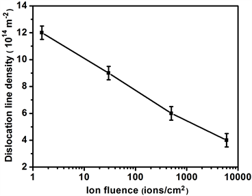
Figure 5. The variation in dislocation density of Ni ions irradiated target for various ion fluences of 15 × 1011 ions/cm2, 30 × 1012 ions/cm2, 50 × 1013 ions/cm2 and 60 × 1014 ions/cm2 at constant energy of 2 MeV.

Figure 6. The variation of residual stress of Ni ions irradiated target for various ion fluences of 15 × 1011 ions/cm2, 30 × 1012 ions/cm2, 50 × 1013 ions/cm2 and 60 × 1014 ions/cm2 at constant energy of 2 MeV.
which are produced simultaneously during ion material interaction. The first phenomenon is production of vacancies and agglomeration of induced vacancies which are finally collapsed into dislocation loop. The other phenomenon is the transference of high amount of energy to the target surface via ion bombardment which leads to generation of high temperature zone on the surface and subsurface. As a result annihilation process is activated [24] . Although more vacancies are produced by increasing ion fluence but at the same time annihilation rate of these induced vacancies also increase. Therefore sink volume increases by increasing irradiation fluence. Because the surface damage by Ni ion irradiation is tremendously high and the surface recovery is impossible [25] .
3.3. Tensile Testing
The stress strain curves of unirradiated and irradiated targets for various fluences are depicted in Figure 7. The mechanical properties of irradiated targets such as Yield Stress (YS) and Ultimate Tensile Strength (UTS) decreases monotonically by increasing ion fluence and is graphically represented in Figure 8 and Figure 9 respectively. The change in YS and UTS of target after ion material interaction is related with the improvement in crystalline size (Figure 4), a reduction in dislocation line density (Figure 5) and ion induced thermal annealing. Similar results have been reported by Zuo [6] , in which after H and N ions irradiation the yield and tensile strength of Ti-6Al-4V alloy are significantly decreased than that of the as-received target sample. The reduction in YS and UTS is also explainable on the basis of thermal spike which is produced by cascade collisions after ion irradiation. The main cause of radiation damage are elastic interactions between incident ions and host atoms of irradiated target lattice, as a result these host atoms displace from their normal stable lattice position.

Figure 7. The comparison of stress-strain curves measured by tensile testing machine of unirradiated and Ni ions irradiated target for various ion fluences of 15 × 1011 ions/cm2, 30 × 1012 ions/cm2, 50 × 1013 ions/cm2 and 60 × 1014 ions/cm2 at constant energy of 2 MeV.

Figure 8. The variation of Yield Stress (YS) of Ni ions irradiated target for various ion fluences of 15 × 1011 ions/cm2, 30 × 1012 ions/cm2, 50 × 1013 ions/cm2 and 60 × 1014 ions/cm2 at constant energy of 2 MeV.
When the value of transferred energy (Em) to the host atoms due to elastic collision is greater than displacement energy (Ed) then the atomic displacement produces. The displacement energy is intrinsic property of the material, the range of its value 20 - 40 eV [26] [27] . But Broeders and Konobevev [27] described that the displacement energy value can change in wider range from 10 eV to 600 eV. The maximum energy transferred to the host atom is directory proportional to ion fluence as well as Ni ion energy and inversely proportional to the atomic mass of the irradiated target material. In this regards, by increasing number of impacts and consequential radiation damage deeply depends on the

Figure 9. The variation of Ni ions irradiated target for various ion fluences of 15 × 1011 ions/cm2, 30 × 1012 ions/cm2, 50 × 1013 ions/cm2 and 60 × 1014 ions/cm2 at constant energy of 2 MeV.
target lattice and cohesive forces of material. The fast moving knock on atoms (PKA) is produced by Ni ions host atom elastic interaction. The energy of PKA atoms (EPKA) can be easily defined by the difference between Ed and Em. The displaced PKA will colloid with other host atoms elastically and produce displacement spike. There is production of thermal spike in the displacement spike just after the ballistic phase. Where the energy of the PKAs is distributed among many atoms to the central core of disorder. As a result temperature of surface and subsurface is increased. The induced temperature during collision cascade is higher than melting temperature of irradiated material for at least 10−12 second. Therefore self and ion induced vacancies and interstitial atoms have higher mobility which leads to the thermal annihilation of vacancies and interstitial defects. The average number of Frenkel pair (vacancies and interstitial defects) decrease with increase in the size of thermal spikes [28] .
3.4. Micro-Hardness
Figure 10 reveals decreasing trend in micro-hardness with increasing Ni ion fluence from 15 × 1011 ions/cm2 to 60 × 1014 ions/cm2. Due to ion induced thermal spike, energy spike and displacement spike, lattice distortion is produced after irradiation. This causes production of Frenkelpairs defects and their annihilation in the normal lattice site of crystal. Therefore decrease in micro-hardness of irradiated target is observed. The reduction in hardness after ion irradiation is directly related to crystallite size and dislocation line density as shown in Figure 4 and Figure 5 respectively. The increase in crystallite size is main reason to decrease the hardness. During ion metal interactions, the energy absorbed is used to increase the mobility of existing and ion induced dislocation defects. As a result the rate of annihilation is dominant than generation of vacancies and interstitial defects [29] . Another vital reason for the reduction in

Figure 10. The variation in the microhardness of Ni ions irradiated target for various ion fluences of 15 × 1011 ions/cm2, 30 × 1012 ions/cm2, 50 × 1013 ions/cm2 and 60 × 1014 ions/cm2 at constant energy of 2 MeV.
hardness of target surface after ion solid interaction is ion induced thermal sputtering [30] .
4. Conclusions
The 2 MeV Ni+ irradiation effects on the surface structural and mechanical properties of Cu-Zn alloy have been investigated successively. The target surface is irradiated with fluence range of 15 × 1011 to 60 × 1014 ions/cm2 by using Pelletron linear accelerator. SEM analysis reveals the formation of nano sized craters after ion irradiation. The density of nano craters increases by increasing the ion fluence, whereas their average diameter decreases from 190 nm to 90 nm.
The XRD analysis of irradiated targets no new phase is formed while growth improvement of (111) phase is clearly observed because of ion irradiation. The development in crystallite size and reduction in dislocation line density are observed by increasing irradiation fluence. It is attributed to the fact that during ion irradiation, vacancies and interstitials defects generated and intrinsic and extrinsic defects turned into collapses during self-annealing phenomenon. This ion induced self-annealing mechanism is responsible for diffraction peak shifting towards the lower angle. The change in YS, UTS and micro-hardness of target after ion material interaction is related with the improvement in crystalline size, a reduction in dislocation line density and ion induced thermal annealing. Due to ion induced thermal spike, energy spike and displacement spike, lattice distortion is produced after irradiation. This causes production of Frenkelpairs defects and their mutual annihilation in the normal lattice site of crystal.
Novelty Statement
In this paper, the modification in properties of brass after 2 MeV Ni+ ions irradiation has been explored. The surface modification has been correlated with the structural as well as mechanical behavior of irradiated brass for the first time. The variation in hardness as well as the strength of material is observed with increasing ion fluence.
Cite this paper
Ahmad, S., Bashir, S., Yousaf, D. and Ali, M.A. (2018) Modification in Cu-Zn Alloy Properties by 2 MeV Ni+ Ions Irradiation. Materials Sciences and Applications, 9, 330-344. https://doi.org/10.4236/msa.2018.93022
References
- 1. Liu, J.C., Li, J. and Mayer, J.W. (1990) Temperature Effect on Ion Irradiation Induced Grain Growth in Cu Thin Films. J ournal of Applied Physics, 67, 2354-2358. https://doi.org/10.1063/1.345530
- 2. Azevedo, C.R.F. (2011) A Review on Neutron-Irradiation-Induced Hardening of Metallic Components. Engineering Failure Analysis, 18, 1921-1942. https://doi.org/10.1016/j.engfailanal.2011.06.008
- 3. Hardie, C.D., Williams, C.A., Xua, S. and Roberts, S.G. (2013) Effects of Irradiation Temperature and Dose Rate on the Mechanical Properties of Self-Ion Implanted Fe and Fe-Cr Alloys. Journal of Nuclear Materials, 439, 33-40. https://doi.org/10.1016/j.jnucmat.2013.03.052
- 4. Ahmad, S., Bashir, S., Ali, N., Kalsoom, U., Yousaf, D., Haq, F., Naeem, A., Ahmad, R. and Rahman, M.K. (2014) Effect of Ion Irradiation on the Surface, Structural and Mechanical Properties of Brass. Nuclear Instruments and Methods in Physics Research Section B: Beam Interactions with Materials and Atoms, 325, 5-10. https://doi.org/10.1016/j.nimb.2014.01.023
- 5. Callister Jr., W.D. (2007) Materials Science and Engineering. John Wiley & Sons, Hoboken.
- 6. Zuo, J.H., Wang, Z.G. and Han, E.H. (2010) The Effect of Ion Irradiation on the Tensile and Fatigue Properties of Ti-6Al-4V Alloy. Materials Science and Engineering A, 527, 3396-3401. https://doi.org/10.1016/j.msea.2010.02.014
- 7. Wang, W., Li, Z., Zhang, Z. and Zhang, C. (2014) 84 MeV C-Ions Irradiation Effects on Zr-45Ti-5Al-3V Alloy. Nuclear Instruments and Methods in Physics Research B, 334, 96-100. https://doi.org/10.1016/j.nimb.2014.05.017
- 8. Zelaya, E., Schryvers, D., Tolley, A. and Fitchner, P.F.P. (2010) Cavity Nucleation and Growth in Cu-Zn-Al Irradiated with Cu+ Ions at Different Temperatures. Intermetallics, 18, 493-498. https://doi.org/10.1016/j.intermet.2009.09.010
- 9. Yang, Z.Y., Jiao, F.F., Lu, Z.X. and Wang, Z.Q. (2013) Coupling Effects of Stress and Ion Irradiation on the Mechanical Behaviors of Copper nanowires. Science China Physics, Mechanics and Astronomy, 56, 498-505.
- 10. Hua, Z., Zhaob, Z., Hua, Y., Xing, J., Lua, T. and Wei, B. (2012) Effect of Ion Irradiation on Mechanical Behaviors of Ti40Zr25Be30Cr5 Bulk Metallic Glass. Materials Research, 15, 713-717. https://doi.org/10.1590/S1516-14392012005000047
- 11. Rehn, L.E., Birtcher, R.C., Baldo, P.M., McCormick, A.W. and Funk, L. (2003) Shock-Wave Production of Nanoparticles during High-Energy Ion Sputtering. Nuclear Instruments and Methods in Physics Research B, 212, 326-331. https://doi.org/10.1016/S0168-583X(03)01423-X
- 12. Popok, V.N. and Campbell, E.E.B. (2006) Beams of Atomic Cluster Effect on Impact with Solids. Rev.Adv.Mater. Sci, 11, 19-45.
- 13. Seki, T., Kaneko, T., Takeuchi, D., Aoki, T., Matsuo, J., Insepov, Z. and Yamada, I. (1997) STM Observation of HOPG Surfaces Irradiated with Ar Cluster Ions. Nuclear Instruments and Methods in Physics Research B, 121, 498-502. https://doi.org/10.1016/S0168-583X(96)00557-5
- 14. Torrisi, L., Ando, L., Gammino, S., Krasa, J. and Laska, L. (2001) Ion and Neutral Emission from Pulsed Laser Irradiation of Metals. Nuclear Instruments and Method in Physics Research B, 184, 327-336. https://doi.org/10.1016/S0168-583X(01)00790-X
- 15. Ashraf, M., Akhtar, S.M.J., Khan, A.F., Ali, Z. and Qayyum, A. (2011) Effect of Annealing on Structural and Optoelectronic Properties of Nanostructured ZnSe Thin films. Journal of Alloys and Compounds, 509, 2414-2419. https://doi.org/10.1016/j.jallcom.2010.11.032
- 16. Chung, Y.M., Jung, M.J., Lee, S.J., Han, J.G., Park, C.G., Ahn, S.H. and Kim, J.G. (2004) A Study of Pulsed Plasma Oxidation Effects on the Corrosion Resistance of Brass. Surface & Coatings Technology, 188-189, 473-477.https://doi.org/10.1016/j.surfcoat.2004.08.055
- 17. Ahmad, S., Bashir, S., Rafique, M.S., Yousaf, D. and Ahmad, R. (2016) The Generation, Detection and Measurement of Laser-Induced Carbon Plasma Ions and Their Implantation Effects on Brass Substrate. Radiation Effects and Defects in Solids, 171, 565-582.
- 18. https://www.engineeringtoolbox.com/
- 19. Shanmugan, S. and Mutharasu, D. (2012) An Effect of N+ Ion Bombardment on the Properties of CdTe Thin Films. Radiation Physics and Chemistry, 81, 201-207.https://doi.org/10.1016/j.radphyschem.2011.09.016
- 20. Soady, K.A. (2013) Life Assessment Methodologies Incoroporating Shot Peening Process Effects: Mechanistic Consideration of Residual Stresses and Strain Hardening Part 1—Effect of Shot Peening on Fatigue Resistance. Materials Science and Technology, 29, 637-651. https://doi.org/10.1179/1743284713Y.0000000222
- 21. Ge, J., Wan, H., Si, N., Ni, K., Ma, Q,. Liu, G. and Xiao, L. (2018) Microstructure Variation of CuZnAl Alloy due to Helium Ions Irradiation. Materials Research Express, 5, Article ID: 016512. https://doi.org/10.1088/2053-1591/aaa333
- 22. Agarwal, D.C., Avasthi, D.K., Singh, F., Kabiraj, D., Kulariya, P.K., Sulania, I., Pivin, J.C. and Chauhan, R.S. (2009) Swift Heavy Ion Induced Structural Modification of Atom Beam Sputtered ZnO Thin Film. Surface & Coatings Technology, 203, 2427-2431. https://doi.org/10.1016/j.surfcoat.2009.02.109
- 23. Kumar, S., Kumar, R. and Singh, D.P. (2009) Swift Heavy Ion Induced Modifications in Cobalt Doped ZnO Thin Films: Structural and Optical Studies. Applied Surface Science, 255, 8014-8018. https://doi.org/10.1016/j.apsusc.2009.05.005
- 24. Rafique, M., Afzal, N., Ahmad, R., Ahmad, S. and Ghauri, I.M. (2012) Mechanical Behavior of Low-Dose Neutron-Irradiated Polycrystalline Zirconium. Radiation Effects & Defects in Solids, 167, 289-297.https://doi.org/10.1080/10420150.2011.644552
- 25. Sivakumar, R., Sanjeeviraja, C., Jayachandran, M., Gopalakrishnan, R., Sarangi, S.N., Paramanik, D. and Som, T. (2008) High Temperature Grown Transition Metal Oxide Thin Films: Tuning Physical Properties by MeV N+-Ion Bombardment. Journal of Physics D: Applied Physics, 41, Article ID: 125304. https://doi.org/10.1088/0022-3727/41/12/125304
- 26. Little, E.A. (1976) Neutron-Irradiation Hardening in Irons and Ferritic Steels. International Metals Reviews, 21, 25-60.
- 27. Broeders, C.H.M. and Konobeyev, A.Y. (2004) Defect Production Efficiency in Metals under Neutron Irradiation. Journal of Nuclear Materials, 328, 197-214. https://doi.org/10.1016/j.jnucmat.2004.05.002
- 28. Srivatsan, T.S., Hanigofsky, M., Sudarshan, T.S. and Legg, K.O. (1992) Influence of Nitrogen Ion Implantation on Tensile Behavior of 1018 Carbon Steel. Thin Solid Films, 213, 27-33. https://doi.org/10.1016/0040-6090(92)90470-V
- 29. Rahman, M.K., Butt, M.Z., Samuel, A. and Siraj, K. (2010) Investigation of Laser Irradiation Effects on the Hardness of Al 5086 Alloy under Different Conditions. Vacuum, 85, 474-479. https://doi.org/10.1016/j.vacuum.2010.08.025
- 30. Ahmad, R., Rafique, M.S., Tahir, M.B. and Malik, H. (2014) Implantation of Various Energy Metallic Ions on Aluminium Substrate Using a Table Top Laser Driven Ion Source. Laser and Particle Beams, 32, 261-270. https://doi.org/10.1017/S0263034614000081