Applied Mathematics
Vol.07 No.10(2016), Article ID:67236,11 pages
10.4236/am.2016.710090
Dynamic Stiffness Analysis of Repetitive Control System
Wu-Sung Yao
Department of Mechanical and Automation Engineering, National Kaohsiung First University of Science and Technology, Taiwan

Copyright © 2016 by author and Scientific Research Publishing Inc.
This work is licensed under the Creative Commons Attribution International License (CC BY).
http://creativecommons.org/licenses/by/4.0/


Received 10 April 2016; accepted 6 June 2016; published 9 June 2016
ABSTRACT
For dynamic stiffness enhancement, this paper presents a new method for synthesizing repetitive controllers capable of rejecting periodic vibration disturbance. Dynamic stiffness of the control system is analyzed. Direct and quadrature dynamic stiffness are defined for the repetitive controllers’ design. A trade-off method between the determinations of the controller’s parameters is necessary such that both the rejecting performance and stability can be achieved simultaneously. An illustrated example of a twin linear drive system is given to verify the performance of the proposed control design. The control performance of the present method is evaluated in the experimental disturbance rejecting control system, where the real-time control algorithms are implemented using a floating-point digital signal processor. Both computer simulation and experimental results are presented to illustrate the effectiveness of the proposed repetitive controller design.
Keywords:
Dynamic Stiffness, Repetitive Control, Twin Linear Drive System

1. Introduction
Repetitive control [1] is one of the specific control schemes in which its objective is to reduce the steady state errors with the periodic inputs. Figure 1 shows a repetitive control system where r is reference input, d is disturbance, y is system output, u is control output, e is error, and  is period of the reference periodic signal. Clearly, the repetitive control system can be achieved for a higher bandwidth with
  and
and , in which the magnitude of the sensitivity function in Figure 1 can be reduced at the harmonics of the input signal within the certain frequency range, i.e.,
  ,
,  , where
  is the fundamental fre-

Figure 1. Repetitive control system.
quency of the input signal r or d, and  is a designed bandwidth. This should be able to improve the tracking/ rejecting performance for periodic input signals but, as expected, easy cause a degradation at intermediate frequencies. The convenience and simplicity of tuning parameters in the repetitive control scheme make it appearing in many industrial drives. Nevertheless, the classical repetitive control scheme may not easily yield satisfactory stability and performance simultaneously when the system has high order dynamic disturbances. The property of the disturbances rejection is often called dynamic stiffness which is substituted for disturbance response. For a disturbances rejection control system, dynamic stiffness is a measure of how many input force is required to cause a unit output deviation. High dynamic stiffness is essential in the anti-vibration control systems for required disturbance rejection ability. In general, the ability of lower frequency disturbance rejection can be referred to static stiffness. Therefore, to achieve better control performance of the repetitive control, the dynamic stiffness should be considered. Let
  denote the transfer function from the disturbance force to the velocity/position output of a control system. The dynamic stiffness can be characterized by
  with a frequency
 . For performance measurement of the dynamic stiffness denoted as,
  , where
  is H-infinite norm. This is the inverse of the maximum magnitude of
 , i.e., the worst case in the frequency response. Thus maximizing the dynamic stiffness measurement implies to minimize
  in controller design.
Many design approaches to improve the dynamic stiffness have been proposed, and the related literatures have been found in the following. In [2] , the high static low dynamic stiffness concept is a design strategy for an anti-vibration mount that seeks to increase isolation by lowering the natural frequency of the mount, whilst maintaining the same static load bearing capacity. In [3] , the flutter characteristics of an actuator-fin system are investigated with structural nonlinearity and dynamic stiffness of the electric motor. The component mode substitution method is used to establish the nonlinear governing equations in time domain and frequency domain based on the fundamental dynamic equations of the electric motor and decelerator. The concept of torque-stiff- ness-controlled dynamic walking is proposed by [4] . The disturbance rejection of torque-stiffness-controlled bipedal walking with Central Pattern Generators is analyzed. [5] presents a dynamic analysis of a stiffened cylindrical shell using the dynamic stiffness method This approach is based on the determination of the dynamic stiffness matrix of an unmeshed structure. A finite element model is used in order to validate the numerical results obtained from the method. The high static low dynamic stiffness concept is proposed by [6] , and is used to increase isolation by lowering the natural frequency of the mount, whilst maintaining the same static load bearing capacity. [7] presents a shape-changeable display with dynamic stiffness control. The prototype uses vacuum pressure control on an enclosed volume of particles. Users can mold 3D shapes and apply textures to them while experiencing tactile feedback through dynamically changing stiffness. In practice, high dynamic stiffness often results in large control effort, hence a trade-off should be considered carefully.
For dynamic stiffness enhancement, this paper presents a new method for synthesizing repetitive controllers applied to anti-vibration system for rejecting periodic disturbance. A trade-off to determine the controller’s parameters is often necessary such that both the control performance and stability can be achieved simultaneously. Moreover, an illustrated example of a single-degree-of-freedom anti-vibration system driven by a two linear motor is given to verify the performance of the proposed control design. Dynamic stiffness of the control system is analyzed. Direct and quadrature dynamic stiffness are defined for the controllers’ design. The control performance of the present method is evaluated in the experimental disturbance rejecting control system, where the real-time control algorithms are implemented using a floating-point digital signal processor. Both computer simulation and experimental results are presented to illustrate the effectiveness of the proposed repetitive controller design.
2. Dynamics Stiffness of Control System
Figure 2 shows a single degree-of-freedom (SODF) mass-damping-spring system, where m is equivalent mass, k is spring coefficient, and c is damping coefficient. x denotes the displacement of the object m. f is disturbance force applied to the inertia loading m. The dynamic equation of Figure 2 is given as . Employing the Laplace transform yields
 , where X and F are Laplace transform forms of x and f respectively.
  is defined as the dynamic stiffness of the system in Figure 2, where the three terms of
  are spring stiffness k, mass-related stiffness
 , and damping-related stiffness
  for frequency
 . Note that the real part of the dynamic stiffness is defined as the direct dynamic stiffness and the imaginary part is the quadrature dynamic stiffness. Therefore, we have
  being the direct dynamic stiffness and
  being the quadrature dynamic stiffness. The magnitude of the dy-
namic stiffness can be obtained, i.e., . A simulated example of
 , c = 2,
and  in Figure 2 is given. Figure 3 shows the magnitudes of the direct dynamic stiffness
  (dashed-dotted line), the quadrature dynamic stiffness
  (dashed-line), and the dynamic stiffness
  (solid-line), where
  and
and  are decreased and increased with increasing
  respectively, and a minimum value of
  can be found.
For a stable control system, DDS and QDS are not zero at the same frequency, and the difference in frequency between the zeros of DDS and QDS is referred to as the margin of stability. If both of the direct dynamic stiffness and the quadrature dynamic stiffness are zero at the same frequency, then  is required, and there is nothing to restrain the vibration amplitude of the system. To further analysis DDS and QDS of a control system, a velocity control system is adopted. Assume that velocity control loop of the motor is given with PDF (pseudo-derivative feedback) controller as shown in Figure 4, where
  and
and  are PDF control parameters. The motor velocity and angular position output are denoted as
  and
and , J is the inertial of the motor, B is the equivalent damping coefficient,
  is the disturbance torque,
  is the motor torque,
  is composed of the torque loop control gain and the motor torque constant,
  is torque input of the servomotor, and
  is velocity command. The dynamic stiffness from the disturbance input
  to angular position output

Figure 2. SDOF mass-damping-spring system.

Figure 3. Magnitudes of  (dashed-dotted line),
  (dashed-line), and
  (solid-line).

Figure 4. Velocity control loop of the motor with PDF controller.
 is
is . Then,
  and
and  can be found. An example of
 ,
,  ,
,  ,
,  , and
, and  is given by Figure 4. Figure 5 shows the magnitudes of
 ,
,  , and
, and  respectively, where
  and
and  are decreased and increased with increasing
  respectively, and minimum value of
  can be found.
3. Dynamics Stiffness of Repetitive Control System
Figure 6 shows a repetitive control system with the period  of the periodic disturbance where the velocity loop control is the same as Figure 5. Therefore, the controlled plant of Figure 6 is
 . The characteristic equation of the closed-loop system in Figure 6 is
found by  where
where . In the repetitive control system of Figure 6, assume that the unity feedback system
  is internally stable.
By the small gain theory, the closed-loop system in Figure 7 is stable if  for all
 ,
,
which is the stability condition of the repetitive control system. Clearly, if  and
and  are chosen to
fit the requirement of  for all
 , then the closed-loop system in Figure 7 is stable. Here, in
practice, let  being low-pass filter with bandwidth
 , i.e.,
  , therefore,
  should be de-
signed for , where
 . Here, let
 ,
,  , then we have
 (1)
(1)
Therefore, for the repetitive control design rule, let  and
and  being given as respectively,
 and
and  (2)
(2)
where  is the designed bandwidth.
The dynamic stiffness from the disturbance input  to angular position output
  is
is
 (3)
(3)
where . For an illustrated example of
 ,
,
 ,
,  , Kp = 0.48, and
 , the parameters of
 ,
,  , and
, and  can be determined. The control response and tracking error of the repetitive control system with
  and
and  can be obtained by Figure 8. Tracking error responses of the repetitive control system with
  (solid-line) and
  (dashed-line) are obtained by Figure 9, where the error with
  is close to that of
 . Figure 10 shows the magnitudes of the direct dynamic stiffness
 , the quadrature dynamic stiffness
 , and the dynamic stiffness
  (solid-line), where
  and
and  will be decreased and increased at the harmonic mode of
  respectively, and minimum value of
  can be found at the harmonic mode of
 . Figure 11 is the illustrated example

Figure 5. Magnitudes of  (dashed-dotted line),
  (dashed-line), and
  (solid-line).

Figure 6. Repetitive control system with the period .
.

Figure 7. A signal regeneration of time delayed system.

Figure 8. Control response of the repetitive control system: Command (solid-line), output (dashed-line), and tracking error (dashed-dotted line).

Figure 9. Error responses of the repetitive control system with  (solid-line) and
  (dashed-line).

Figure 10. Magnitudes of  (dashed-dotted line),
  (dashed-line), and
  (solid-line).

Figure 11. Experimental setup.
of the two linear servomotors with the mechanical coupling in this study, where a linear motor is given as the target plant and the other one is a disturbance generator. Assume that the velocity of the motor can be estimated or measured by encoder. The control system was purposely developed for experimental study to verify the control performance of the proposed repetitive control scheme. The objective of the control design is to reduce vibrations of the controlled target. In fact, a control system modeling of the experimental setup can be detailed as shown in Figure 12, where the parameters are listed the following.
 : spring coefficient of the disturbance generator
 : mass of the disturbance generator
 : damping coefficient of the disturbance generator
 : displacement of the disturbance generator
 : force generated by the disturbance generator
 : mass of the target linear motor
 : damping coefficient of the target linear motor
 : force generated by the target linear motor
 : displacement of the target linear motor
 : spring coefficient of the mechanical coupling
 : damping coefficient of the mechanical coupling
 : mass of the mechanical coupling
 : spring coefficient of the mechanical coupling
 : damping coefficient of the mechanical coupling
 : displacement of the mechanical coupling
Then, we have the control block diagram of the experimental system as shown in Figure 13. To design an anti-vibration controller, the controlled system in Figure 13 can be simplified to a second-order dynamic systemas depicted in Figure 14. k and c denote the equivalent stiffness and damping effects of the passive anti-vibration elements, respectively.  and
and  are the equivalent loading of the mechanical elements and the equivalent mass of the disturbance generating device, respectively. Based on Figure 14, the dynamic equation of the proposed anti-vibration system is given as (2), and its Laplace transform can be given (3). Note that
 ,
,  ,
,  , and
, and  are the Laplace transform form of
 ,
,  ,
,  , and
, and  respectively.
 (4)
(4)
For the requirement of  with
with , the control force of the linear motor should be given as
 . In practice, the information of
  is difficult to obtain. Therefore, in this paper, an
appropriate control scheme is adapted to reduce the effect of the disturbance . Under
 , the dynamics of the system is given as
 . Assuming
  in this case, we
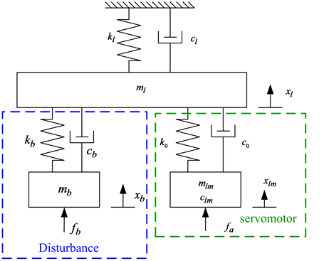
Figure 12. System modeling of experiment setup of Figure 11.

Figure 13. Control block diagram of controlled system.

Figure 14. Block diagram of proposed anti-vibration system.
have .
.
In this paper, an anti-vibration control system can be described with a feedback controller  as shown in Figure 15. As shown in Figure 16,
  performs a repetitive controller. Note that
  is a periodic disturbance forced by a linear servomotor. In the paper, a control strategy of the disturbance rejection control (see Figure 16) is proposed for the illustrated example. The position loop and velocity loop controllers (proportional + pseudo derivative feedback feed-forward, P + PDF) are pre-designed to stabilize the control system for the
required performance. In this case,  can be obtained. Let the bandwidths of the velocity and po-
sition loops be set to 40 Hz and 15 Hz respectively, which is just for general requirement of the motion control performance of the linear motor. For the velocity control loop, the control parameters of ,
,  , and
, and  can be designed. Considering the control system of Figure 16 without repetitive control, we have the transfer
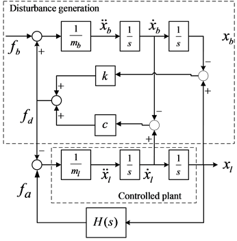
Figure 15. Block diagram of the active anti-vibration control system with feedback controller .
.

Figure 16. Block diagram of the anti-vibration control system with repetitive controller and PDF loop controller.
function of the velocity control loop, i.e.,  where
where  and
and
 . In this case,
  ,
,  , and
, and  are obtained. The bandwidth of the
velocity control loop  and the damping ratio
  are pre-determined. Therefore, the control parameters of
  and
and  are calculated. For the position control loop of Figure 16 without the repetitive control, the bandwidths of the position loop is given by
 , therefore, the position-loop control gain
  can be obtained. The frequency responses of position and velocity control loop in Figure 16 are shown in Figure 17.
From Figure 16, the controlled plant  can be obtained. Based on the design rule of (1), the parameters of the repetitive controller can be calculated as
 ,
,
and . To verify the control scheme, a multiple period’s disturbance signal of
 ,
,  , Td3 = 3 s with magnitude of 1 is given as shown Figure 18(a). The result can be found that the error is gradually decaying as shown in Figure 18(b). For a time-varying periodic signal of
 ,
,  ,
,  , and
, and , the harmonics of
  and
and  are within
 , that of
  is at
is at , and that of
  is for
  (see Figure 19(a)). The result can be found that the tracking error is gradually decaying as shown in Figure 19(b). The larger errors can be found at 3 s, 5 s, and 6 s, which is generated by the non-continuous of the variable instantaneous frequencies period’s signal.
4. Conclusion
This paper presented a new method for synthesizing repetitive controllers capable of rejecting periodic vibration disturbance. Dynamic stiffness of the control system is analyzed. Direct and quadrature dynamic stiffness are
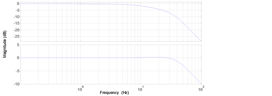
Figure 17. Frequency responses of position and velocity control loop.
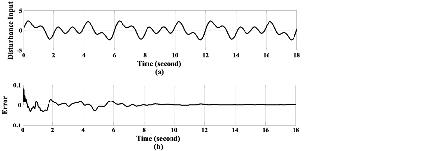
Figure 18. Experimental result: (a) the disturbance input and (b) error response.
 (b)
(b)
Figure 19. Experimental result: (a) the disturbance input and (b) error response.
defined for the repetitive controllers’ design. An illustrated example of a twin linear drive system is given to verify the performance of the proposed control design. The control performance of the present method is evaluated in the experimental disturbance rejecting control system, where the experimental results are given to illustrate that the proposed repetitive control can effectively eliminate steady-state rejecting errors within a few cycles.
Cite this paper
Wu-Sung Yao, (2016) Dynamic Stiffness Analysis of Repetitive Control System. Applied Mathematics,07,1032-1042. doi: 10.4236/am.2016.710090
References
- 1. Tsai, M.C. and Yao, W.S. (2002) Design of a Plug-In Type Repetitive Controller for Periodic Inputs. IEEE Transactions on Control Systems and Technology, 10, 547-555.
http://dx.doi.org/10.1109/TCST.2002.1014674 - 2. Zhou, N. and Liu, K. (2010) A Tunable High-Static-Low-Dynamic Stiffness Vibration Isolator. Journal of Sound and Vibration, 329, 1254-1273.
http://dx.doi.org/10.1016/j.jsv.2009.11.001 - 3. Yang, N., Wu, Z. and Yang, C. (2011) Structural Nonlinear Flutter Characteristics Analysis for an Actuator-Fin System with Dynamic Stiffness. Chinese Journal of Aeronautics, 24, 590-599.
http://dx.doi.org/10.1016/S1000-9361(11)60069-1 - 4. Huang, Y. and Wang, Q. (2015) Disturbance Rejection of Central Pattern Generator Based Torque-Stiffness-Controlled Dynamic Walking. Neurocomputing, 170, 141-151.
http://dx.doi.org/10.1016/j.neucom.2015.04.096 - 5. Tounsi, D., Casimir, J.B., Abid, S., Tawfiq, I. and Haddar, M. (2014) Dynamic Stiffness Formulation and Response Analysis of Stiffened Shells. Computers and Structures, 132, 75-83.
http://dx.doi.org/10.1016/j.compstruc.2013.11.003 - 6. Shaw, A.D., Neild, S.A. and Wagg, D.J. (2013) Dynamic Analysis of High Static Low Dynamic Stiffness Vibration Isolation Mounts. Journal of Sound and Vibration, 332, 1437-1455.
http://dx.doi.org/10.1016/j.jsv.2012.10.036 - 7. Toshiki, S., Jefferson, P., Yasushi, M. and Hideki, K. (2014) Claytric Surface: An Interactive Deformable Display with Dynamic Stiffness Control. IEEE Computer Graphics and Applications, 34, 59-67.
http://dx.doi.org/10.1109/MCG.2014.39