Smart Grid and Renewable Energy
Vol.2 No.4(2011), Article ID:8270,12 pages DOI:10.4236/sgre.2011.24036
Advanced Metering Infrastructure for Electric Vehicle Charging
![]()
1Department of Electronic Engineering, City University of Hong Kong, Hong Kong, China; 2School of Engineering & Mathematical Science at City University London, London, UK; 3State Grid Energy Research Institute, Beijing, China.
Email: *ee330015@cityu.edu.hk
Received August 24th, 2011; revised September 17th, 2011; accepted September 24th, 2011.
Keywords: Electric Vehicle Charging, Advanced Metering Infrastructure, Power Line Communication, Demand Response
ABSTRACT
The widely adoption of Electric Vehicle (EV) has been identified as a major challenge for future development of smart grids. The ever increasing electric vehicle charging further increases the energy demand. This paper reports the development of an Advanced Metering Infrastructure (AMI) as an effective tool to reshape the load profile of EV charging by adopting appropriate demand side management strategy. This paper presents a total solution for EV charging service platform (EVAMI) based on power line and internet communication. It must be stressed that the development of Third Party Customer Service Platform in this investigation facilitates a single bill to be issued to EV owners. Hence, EV owners understand their energy usage and thus may perform energy saving activity efficiently. Experiment and evaluation of the proposed system show that the throughput achieved is about 5 Mbps at 10 ms end to end delay in Power line Communication. By introducing two dimensional dynamic pricing and charging schedule, the proposed EVAMI successfully reduces 36% peak consumption and increases the “off peak” consumption by 54%. Therefore the EVAMI does not only reduce the peak consumption but also relocates the energy demand effectively.
1. Introduction
The Electrical Vehicle (EV) development has become a hot topic recently. The global market of EV will reach 2.6 million units in 2015. The carbon release due to EV charging is arousing critical environmental concerns. Apart from environmental and economical reasons, the most significant driving force of EV market is strong policy, including legislations, benefits and rebates from various governments. Regardless of the initiative, the rapid growth of electric vehicle definitely increases the energy demand. It was reported that the extra energy demand of EV may further increase the peak demand and cause the distribution circuit congestion [1-5]. More importantly, it was pointed out that the EV hype may reduce CO2 emission if appropriate demand side management (DSM) strategy is adopted. In [1], it was high-lighted that the U.S electric infrastructure is designed to meet the highest expected demand for power, which only occurs a few hundred hours a year (at most 5% of the time). For 95% of the time, the electric grid is seriously underutilized and therefore huge amount of green gas is generated unnecessarily. Unfortunately, the U.S. electric grid is not a special case. Most of the developed areas have adopted a similar approach to stabilize the electricity supplies. To fully utilize the electric infrastructure, researchers have proposed numerous DSM strategies [6,7] for EV charging. It is also well documented that by adopting centralized control of EV charging, peak demand will be more accurately estimated and hence will significantly benefit the utility [8-10]. The centralized control EV charging may be achieved by enabling dynamic demand response, load profile flattening and improved generation resource utilization. On the other hand, a prepaid smart metering scheme for Smart Grid application based on centralized authentication and charging using the WiMAX prepaid accounting model was developed [11]. However, this smart metering scheme was designed for payment only and important services such as demand monitoring, customer service, meter management service, etc. were ignored. Although, the role and proposed features of EV Advance Metering Infrastructure (AMI) have been discussed in [12], the practical design of the entire system is missing. It is thus notified that a full feature AMI for EV charging service is desperately required. Similar to typical AMI system, the EV AMI measures, collects and analyzes energy consumption from EV charging station regularly via communication links. “Infrastructure of AMI” refers to a network that connects the measurement devices to utility servers allowing data collection and distribution of information to customers, suppliers, utility companies and service providers. Interactive communication carries distinctive meaning of AMI because the influence of real-time energy consumption on users’ charging behavior was documented. With the timely information, utility easily monitor energy demand on time and location basis. In this paper, an AMI platform for EV charging (EVAMI), enabling data exchange between automobile owners, Utility information systems (e.g. MDMS, billing) and the electric vehicle charging stations, are introduced. Owing to the requirement for high availability, the proposed solution adopts Power Line Communication (PLC) for network of onsite charging system which transmits data via the powerline. Therefore, no extra effort is necessary for rewiring and yet high scalability is achieved. As a result, EV charging may take place in a wide range of locations such as multi-storey car parks. This paper is organized as follows: the demand response EV AMI system is discussed in Section 2. The system architecture, protocol design and implementation are discussed in Section 3. The performance evaluation is discussed in Section 4. Finally, a conclusion is drawn in Section 5.
2. EVAMI Overview
In this section, the system overview of EVAMI is presented. EVAMI is a total solution which serves utility employee and EV owners. It should be noted that EV owners possess varying characters ranging from normal energy consumers to huge energy consumption users and yet it is anticipated that EV owners may charge their vehicles at different locations. Thus PLC seems one of the potential candidates. The versatility of the PLC system is that the onsite charging system can be connected to the utility management system by collaborating with ordinary internet access technologies such as WiMAX, LTE, Optical fiber… etc. to provide TCP/IP communications.
1) Advantage of Adopting EVAMI In general EV charging consumers will receive electricity bills from multiple utilities. In such a circumstance, it is difficult to obtain the personal consumption profile of individuals from a single utility. One of the salient features of the developed EVAMI is that a third party customer information platform (a neutral platform) is implemented to serve various utilities. The key contribution in this paper is that the proposed EVAMI facilitates an owner to obtain a single charging bill that includes the overall charging profile. The EVAMI (Figure 1) is divided into three parts: Onsite Charging System, Third Party Customer Service platform and Utilities Information Management System.
2) Choice of Signal Transmission Platform Since signals are typically transmitted over a long distance, an inexpensive and yet reliable transmission medium must be employed. Wireless transmission may be a good choice but the skills required may be complex. On the other hand, wireline transmission requires preinstallation which may be tedious and sometimes impossible because of the need for renovation. Alternatively, PLC may be used since it facilitates ease of deployment and flexibility of modification. The cost and weight of the power line are also comparatively lower [13]. For short to medium distance where signals do not have to change phase nor to go through transformers, PLC is a potential technology candidate for Local Area Network (LAN). Typically a PLC LAN should be no more than 10km. PLC, specified by the HomePlug 1.0/1.1 standard [14], provides a 14/85 Mb/s raw data rate. This is adequate for most electronic device communications. The PLC systems operate by imposing a modulated carrier signal into the power line. Depending on the signal transmission characteristics of the power line used, PLC may operate in different frequency bands. In this work, PLC is adopted in order to furnish the captioned features into the EVAMI. The PLC module is shown in Figure 2 and the specification of the PLC module is listed in Table 1.
2.1. Onsite Charging System
Onsite Charging system (OCS) consists of an electric vehicle charging station (EVCS) and a Data Concentration Unit (DCU). The function of CS is to serve EV
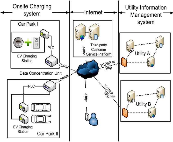
Figure 1. EVAMI overview.

Figure 2. Block diagram of PLC module.

Table 1. Specification of PLC module.
owners in car parks. Generally, it handles the initializetion and termination of the charging session. During the charging period, the OCS monitors the charging status and updates the meter reading. It also monitors the health status of the CS. The DCU is a PLC internet gateway which supports TCP/IP communication and connects the OCS to the UIMS. In this work, PLC is adopted in order to furnish the captioned features into both the EVCS and DCU.
EV Charging Station EVCS (refer to Figure 1) is composed of an electric power plug and a smart meter. Basically, the EVCS informs the DCU whether a EV has been plugged in or not. The charging process is designed not to start immediately after plug-in. To avoid unauthorized use of service, the EVCS starts the charging session only after receiving the activation command from the DCU. It then authorizes the charging and monitors the entire charging session and provides detailed report of the charging session. Furthermore, the EVCS equips self-healing ability and reports to the DCU when fault or error is detected. The operation flow of the EVCS is summarized in Figure 3.
2.2. Utility Information Management System
Utility Information Management System (UIMS) bridges the OCS, the Third Party Customer Service Platform and other smart grids applications in order to provide billing services and perform demand response operations. Based on TCP/IP protocol, the UIMS collects the real time charging service data from numerous car parks. As a result, the UIMS not only provides the real time personal consumption profile to customers but also timely location based energy demand to utilities. By incorporating such information, the DR policy can be defined with slight effort. The UIMS forwards the defined policy to the OCS

Figure 3. Operation flow of the EVCS.
and the TPCSP. In addition to DR, UIMS also provides information to MDMS of utilities for billing. By updating the service record of TPCSP, a single bill can be issued to customers. To facilitate data processing, an administrative web portal is designed for the UIMS. The web portal provides EV energy demand reports to utility employees and manages customer data.
2.3. Third Party Customer Service Platform
Third Party Customer Service Platform (TPCSP) is a neutral platform which interacts with multiple UIMS. Differentiated from UIMS, TPCSP serves the EV owner through a web portal for charging service. TPCSP collects service records from numerous utilities and combines them to form a single bill disclosing the overall personal consumption profile. Therefore, an EV owner may record an overall consumption habit due to EV charging. More importantly, TPCSP enables the communication between EV owners and utilities so that utilities can deliver their message to EV at anytime. Therefore, the TPCSP does not only benefit EV owners but also utilities by fostering an efficient DR platform.
3. System Architecture, Protocol Design and Implementation
EVAMI adopts a three-tier architecture including the web tier, the application tier and the enterprise information tier. The web tier handles the presentation and communication function while the application tier supports the business intelligence and the enterprise information tier so that data may be organized systematically. The system architecture of EVAMI is illustrated in Figure 4.
By considering the system functions, EVAMI can be divided into five subsystems: Car Park Management Sub-

Figure 4. System architecture.
system, Meter Management Subsystem, User Management Subsystem, Demand Response Service Subsystem and Billing Service Subsystem. Each of the subsystem serves clients for different purposes.
Car Park Management Subsystem The Car Park Management Subsystem (CPMS) records, handles and processes the data of car park. The CPMS is comprised of two major components: Car Park Management Service Module (CPMSM) and Car Park Information Database (CPIDB). CPMSM helps service managers of utilities to manage the information of car park, thus an EV owner may obtain the updated information via the portal.
Meter Management Subsystem The Meter Management Subsystem (MMS) records, handles and processes the data of a meter. The MMS is comprised of two major components: Meter Management Service Module (MMSM) and Meter Information database (MIDB). The MMS collects meter reading and status from OCS to enable service mangers and EV owners to obtain the energy consumption data though web portals. Furthermore, the MMS monitors the status of the meter and generates meter error report automatically should operation failure is detected. The report will be delivered to the service manager via emails and warning messages will also be displayed on the web portal.
User Management Subsystem The User Management Subsystem (UMS) records, handles and processes the data of users. The UMS is comprised of two major components: the User Management Service Module (UMSM) and the User Information Database (UIDB). The UMSM identifies the role of users and helps service mangers to manage the information of EV owners. The UIDB stores the personal details of EV owner.
Demand Response Subsystem The Demand Response Subsystem (DRS) records, handles and processes the data of users. The DRS is comprised of two major components: Demand Response Service Module (DRSM) and Demand Response policy database (DRPDB). Under normal circumstance, the UIMS updates the DR policy regularly in order to fulfill the energy demand. The most update policy is stored to the DRPDB. The DRSM generates DR signals and transmits them to the DCU and the TPCSP. The TPCSP then informs EV owners by displaying messages in “welcome page” of the web portal or during the charging service subscription.
Billing Service Subsystem The Billing Service Subsystem (BSS) records, handles and processes the billing data. The BSS is comprised of two major components: the Billing Service Module (BSM) and the Billing Information Database (BIDB). The BSS cooperates with MMS and UMS to generate the most updated payment record.
3.1. Communication Protocol
To support the operation of above subsystems, a series of communication protocol has been defined to cater for the Charging Service Session Management, Demand Response and Device Management.
3.1.1. Charging Service Session Management
The Charging Service Session Management (CSSM) consists of two parts: Charging Service Session Initialization and Charging Service Session Termination.
1) Charging Service Session Initialization The Charging Service Session Initialization (CSSI) process involves mobile users, TPCSP, UIMS and OCS. The detailed procedure is summarized in Figures 5 and 6. Figure 5 describes the interaction between the EVCS and the DCU during charging service initialization. Once the smart EVCS is plugged in, it updates its current status to the DCU with updated commands. The DCU will start the timer and wait for service activation from the utility server. After the timeout period or when the service activation is received, the DCU sends the “decision” service command to the EVCS. The EVCS will start and stop service corresponding to the decision. The EVCS then sends the service command and the updated commands to the DCU. The Service Command consists of the charger information, the consumption and the time stamp to facilitate the DCU to upload the service record to the utility server. The EVCS then updates its current status to the DCU with updated commands. It should be pointed out that the DCU is only the intermediate node of the
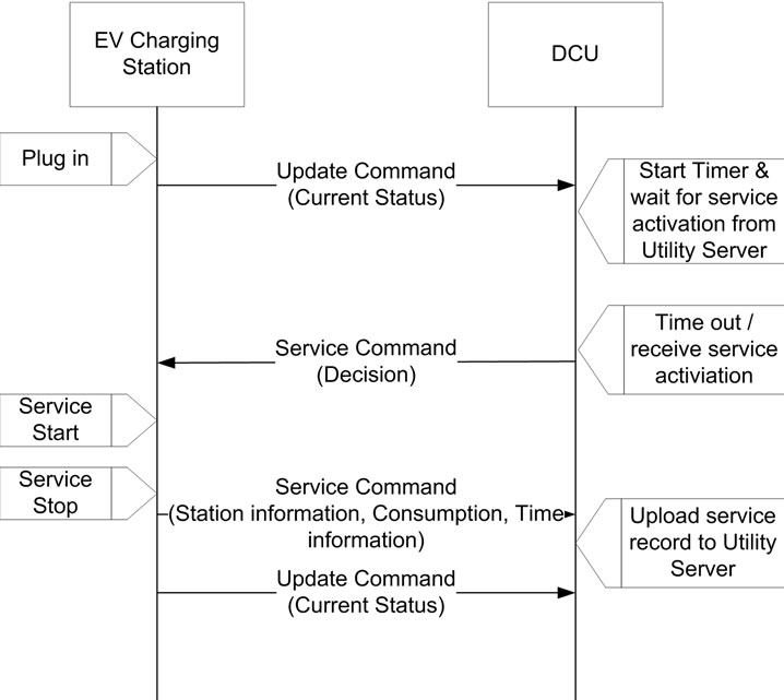
Figure 5. Interaction between EVCS and DCU during charging process.
communication. The communication between the DCU, TPCS platform, UIMS and user is illustrated in Figure 6.When an EV starts a charging session, the DCU receives “Plug in” status from the EVCS. The user is required to complete the authentication process with the third party server before “requests for service” is allowed. The third party server then receives the service request including user information, target charger information and service content. The third party server will then set up connection with the utility server. Authentication between two servers is needed and the third party sends the service request containing the target charger formation and the service content to the utility server. The utility server sets up connection with the DCU and carries out the authentication process. After authentication is completed, service activation including target charger information and service content will be received by DCU. The EVCS then starts charging and the DCU will send a service confirmation with target charger information and status to the utility server. The connection between the utility server and the DCU will be shut down. The utility server then forwards the service confirmation to the third party server and the third party server will shut down the connection with the utility server. Finally, the user then receives the status from the third party server.
2) Charging Service Session Termination The Charging Service Session Termination (CSST) process involves mobile users, TPCSP, UIMS and OCS. The detailed procedure is summarized in Figure 7. When the charging process is finished, the DCU receives the service termination from the EVCS. The DCU then sets up connection with the utility server. When the authenticcation process is completed, the DCU forwards the service termination commands including the target charger information and the service summary to the utility server. The connection between the DCU and the utility server is then shut down and the utility server will set up connection with the third party server. The two servers will complete the authentication process. The utility server then sends the service termination to the third party server and the utility server shuts down the connection with the
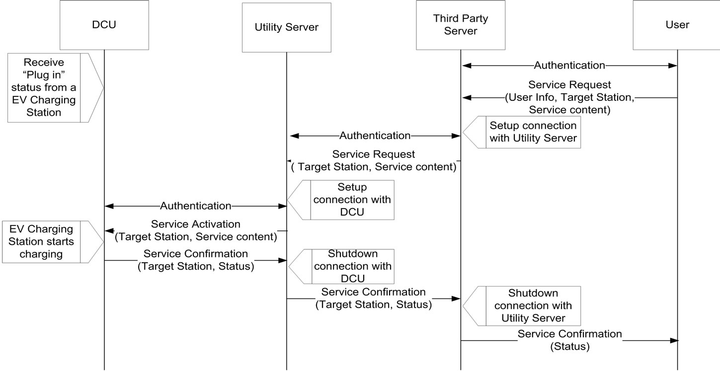
Figure 6. Data flow between DCU, UIMS, TPCS platform and user mobile during service initialization process.
third party server. After the third party server has received the service termination, a service status alert with service summary and status will be sent to users.
3.1.2. Device Management
EVCS Failure Report The EVCS failure report procedure is described in Figure 8. The EVCS and the DCU carry out health monitoring periodically. When the EVCS detects a failure, it sends a failure report to the DCU to report the charger information, time and error code. Then the DCU will set up a connection with the utility server. After the authentication process is completed, the DCU forwards the failure report to the utility server, and the connection between the DCU and the utility server will be shut down. The utility server then sets up the connection with the third party server and performs authentication. Afterward, the utility sends the “service suspension notifycation” which includes charger information, start time and end time to the third party server. The connection between the two servers will then be shut down.
3.1.3. Demand Response Management
The EVAMI performs the demand response in two approaches: dynamic pricing and charging session sched uler. The operations of two demand response approaches are presented in Figure 9 and Figure 10.
1) Energy Price Modification Dynamic pricing has well been recognized as an effective approach to reshape the load profile [6-10]. By offering attractive energy price, utility increases the energy demand during the off peak hours. Meanwhile, util-

Figure 7. Data flow between DCU, UIMS, TPCS platform and user mobile during service termination process.

Figure 8. EVCS failure report procedure.
 (a)
(a) (b)
(b)
Figure 9. Energy price update procedure.
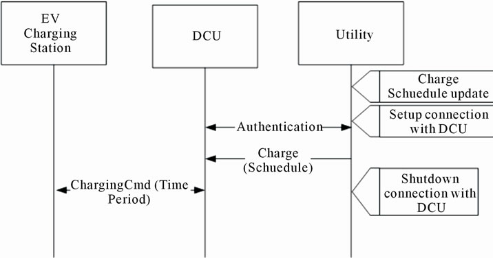
Figure 10. Charging session schedule update.
ity reduces the energy demand by raising the energy price in the rush hours. As a result, the load profile is flattened. To update the Time of Use (TOU) price, the utility server will set up a connection with the DCU and complete the authentication process. The utility sends the updated setting of time period and price to the DCU, and the connection is shut down afterward. The DCU then forwards the most update setting to the EVCS to facilitate the DCU to set up a connection with utility server. After the authentication process is completed, the DCU exchanges the setting report with update setting summary to the utility server. The DCU shuts down the connection after then.
When the utility server has received the TOU price update, it also sets up a connection with the third party server. The authentication process is carried out and the two servers exchange the price update notification with price update summary. The connection between the two servers will be shut down. Finally, the third party server exchanges the price update notification with user.
2) Charging Session Schedule update The Charging session scheduler is invoked when a new charging session is initialized. In general, the scheduler will schedule the charging service at off peak hours to minimize loadings due to EV charging. The procedure of updating the charging scheduler is illustrated in Figure 10. To update charging schedule, the utility server sets up connection with the DCU. Once the authentication is completed, the utility server sends the charging schedule to the DCU. The connection will shut down afterward. The DCU then forwards the charging schedule comprising the time period data log to the EVCS.
3.2. Web Portal
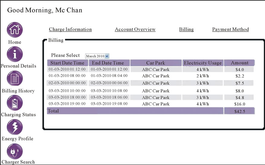
Two web portals have been developed to serve the service manager and the EV owner. The user interfaces are shown in Figure 11 and Figure 12 respectively. By incorporating the web portal, the service manger may capture the full EV charging service via the portal. Such information includes the overall energy profile—both time and location based data (Figure 11), customer information and status of each charger. Such timely information shifts the paradigm of dynamic pricing from single dimension (time series) to two dimensions (time and geography). In contrast, EV owners may obtain the energy profile of their EV charging, electronic bill (Figure 12(a)) as well as monitoring the charging status of their vehicles (Figure 12(b)). More importantly, EV owners may obtain the real-time EV parking information which ensures EV owners to enjoy charging service.
4. Performance Evaluation
In this section, the performance of EVAMI is reported. There are two parts: The first part investigates the network performance of OCS and the second part evaluates the effectiveness of EVAMI for DR applications.
4.1. Network Performance of OCS
An experiment was conducted to investigate the network performance of OCS. Without losing generality [15], OCS based on six EVCSs was devised during experiment. The network throughput and end to end delay were measured under three different system occupanies: 1) 0%, 2) 50% and 3) 100% implying 4) all EVCSs are idle, 5) three EV are charging and (6) all EV are charging respectively. The results are shown in Figure 13.
 (a)
(a)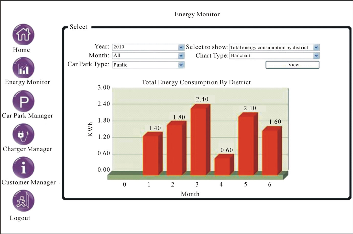 (b)
(b)
Figure 11. User interface for service manager.
 (a)
(a) (b)
(b)
Figure 12. User interface for EV owner.

Figure 13. Network performance of OCS.
In Figure 13, The End to End delay of OCS is bounded by 11.2 ms while the system throughput ranges from 4.6 to 5.1 Mbps. In general, End to END delay increases as the system occupancy increases because the traffic loadings of the system increases when more charging service sessions are established. Apart from the traffic loadings, interference is another important factor yielding performance degradation. When a EV is plugged into the system and the charging process is started, interference is also injected into the PLC network. Therefore, the packet error may increase during transmission. As a result, the system throughput will drop.
4.2. Effectiveness of EVAMI on Demand Response
To investigate the effectiveness of EVAMI for DR applications, a case study has been conducted. An efficient AMI system normally carries high traffics; hence heavy loadings are studied. As a result, the load profiles of residential buildings are collected by recording the meter readings every thirty minutes. The monitored residential building was sixty floors tall and there were eight apartments on each floor. The energy consumption for 420 apartments was measured and the study lasted for two months. The average thirty minutes energy consumption of the entire residential building is indicated as normal in Figure 14 and Figure 15.This study postulates an EV scenario that is based on the average driving requirement of 25km per day which is estimated from the Hong Kong government data [16,17].
The definition of the three charging level is recalled and is listed in Table 2. In Figure 14, the impact due to different EV charging level on the load profile is investigated. In additional to the Charging level, Figure 14 also considers the effect of EV penetration, from 10% to 30%, on the load profile, Nevertheless, The increase of EV penetration yields an increase of energy demand. For normal practice, customers charge their EV at around 20:00. Without any demand response policy, peak consumption raises 65% if 10% of residences charge their EV with level 1 charging mode. It should be noted that the peak energy demand dramatically jumps to 1778 kWh (560% of normal case) if 30% of residential charge their EV with level 3 charging mode. It is thus seen that the penetration of EV and charging level significantly affect the peak energy demand. Therefore, level 1 charging mode is concluded as the most appropriate charging method for charging scheduler of EVAMI. The global penetration of hybrid EV is estimated to be over 10% from 2012 to 2015 [19,20]. To reflect a realistic projection, the EVAMI performance is evaluated based on the assumption that 10 % of residents charge their EV with Level 1 charging. The findings are shown in Figure 15. Without the EVAMI, the peak energy demand reaches 440 kWh when 10% of residents charge their EV with level 1 charging. After applying scheduler of EVAMI, the peak energy consumption is reduced by 36% (which falls to 280 kWh). More importantly, EVAMI successfully increases the energy demand at “off peak” by 54%. This investigation reveals that the EVAMI does not only reduce the peak consumption but also relocate the energy demand effectively. From [21], saving 1 Wh peak demand reduces 50 Wh non-coincidental peak load. If EVAMI is widely adopted in Hong Kong, 3.3 TWh electricity consumptions are saved annually when penetration of EV has reached 10%. At the same time, 2.2 G Tonnes CO2 emission is reduced which worth HK $3.3 G. Apart from benefiting the utilities, EVAMI also provides a full function web portal to the EV owners. TPCPS interacts with different utilities’ information systems to collect all EV charging service transactions and therefore a single bill can be issued to EV owners. As a result, EV owners may obtain the overall profile of their EV charging usage.
5. Conclusions
In this paper, an AMI platform for EV charging (EVAMI) is proposed to furnish a wide range of features to both EV owners and utility service managers. By enabling the interactive and efficient communication platform, the
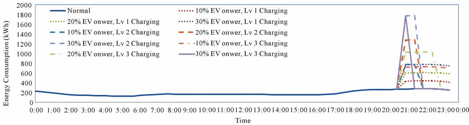
Figure 14. Impact of EV charging level on load profile of a residential building.

Figure 15. Impact of EV AMI on load profile of a residential building.

Table 2. Definiation of charging level [18].
proposed EVAMI facilitates utilities to perform demand response effectively. Apart from the traditional demand response approach, a charging scheduler is introduced to advice the charging mode and the schedule to EV Charging Station in order to reshape the load profile. As such, the proposed solution not only provides the time based load profile but also the location based load profile. Such timely information shifts the paradigm of dynamic pricing from a single dimension (time series) to two dimensions (time and geographic). It must be stressed that the incorporation of Third Party Customer Service Platform (TPCSP) facilitates a single bill to be issued to EV owners. Hence, EV owners understand their energy usage and thus may perform energy saving activity.
In this investigation, the Power Line Communication network has been proposed. Evaluation of the performance shows that a data rate of 4.6 Mbps to 5.1 Mbps with an end to end delay of 9.8 ms to 11 ms is achieved. It must be stressed that the invention of TPCPS in the EVAMI allows a single bill to be issued to EV owners.
Furthermore, an insight in the impact of charging level on the load profile is also provided. In general, level 1 charging has less effect on the load profile than level 2 and level 3 charging. In particular, the level 3 charging shapes the load profile in a “sharp peak”. In this work, the charging scheduler only carries out demand response by adopting level 1 charging and an appropriate schedule. As a result, the peak energy consumption is reduced by 36%, i.e. from 440 kWh to 280 kWh. More importantly, the adoption of EVAMI successfully increases the energy demand at “off peak” by 54%. It is important to point out that the EVAMI does not only reduce the peak consumption but also relocates the energy demand effecttively.
6. Acknowledgements
Acknowledgement is expressed to the provision of expertise and measurement equipments from Citycom Technology Ltd..
REFERENCES
- A. Ipakchi and F. Albuyeh, “Grid of the Future,” IEEE Power and Energy Magazine, Vol. 7, No. 2, 2009, pp. 52- 62.
- M. C. Kintner-Meyer, et al., “Impacts Assessment of Plug-in Hybrid Vehicles on Electric Utilities and Regional US Power Grids: Part 1: Technical Analysis,” Pacific Northwest National Laboratory (PNNL), (PN NLSA-61669), 2007. http://www.ferc.gov/about/com-mem/wellinghoff/5-24-07-technical-analy-wellinghoff.pdf
- “Environmental Assessment of Plug-in Hybrid Electric Vehicles,” Electric Power Research Institute, Inc., Pola Alto, 2007. http://mydocs.epri.com/docs/CorporateDocuments/SectorPages/Portfolio/PDM/PHEV-ExecSum-vol1.pdf
- M. Duvall, “How Many Plug-in Hybrids Can a Smart Grid Handle?” Plug-in 2008 Conference and Exposition, San Jose, 2008.
- S. W. Hadley and A. A. Tsvetkova, “Potential Impacts of Plug-in Hybrid Electric Vehicles on Regional Power Generation,” 2007. http://www.ornl.gov/info/ornlreview/v41_1_08/regional_phev_analysis.pdf
- G. A. Putrus, P. Suwanapingkarl, D. Johnston, E. C. Bentley and M. Narayana, “Impact of Electric vehicle on Power Distribution Network,” The Proceeding of IEEE Vehicle Power and Propulsion Conference 2009, Dearborn, 7-10 September 2009, pp. 827-831.
- M. D. Galus and G. Andersson, “Demand Management of gird Connected Plug-in Hybrid Electric Vehicles (PHEV),” IEEE Energy 2030 Conference 2008, Atlanta, 17-18 November 2008, pp. 1-8
- W. Short and P. Denholm, “Preliminary Assessment of Plug-in Hybrid Electric Vehicles on Wind Energy Markets,” National Renewable Energy Laboratory (NREL), 2006, (NREL/TP-620-39729). doi:10.2172/881921
- P. Denholm and W. Short, “Evaluation of Utility System Impacts and Benefits of Optimally Dispatched Plug-in Hybrid Electric Vehicles,” National Renewable Energy Laboratory (NREL), 2006, (NREL/TP-620-40293). doi:10.2172/888683
- K. Parks, et al., “Costs and Emissions Associated with Plug-In Hybrid Electric Vehicle Charging in the Xcel Energy Colorado Service Territory,” National Renewable Energy Laboratory (NREL), 2007 (NREL/TP-640-41410). doi:10.2172/903293
- R. H. Khan, T. F. Aditi, V. Sreeram and Herbert H. C. Iu, “A Prepaid Smart Metering Scheme Based on WiMAX Prepaid Accounting Model,” Smart Grids and Renewable Energy, Vol. 1 No. 2, pp. 63-69, 2010
- D. Rua, D. Issicaba, F. J Soares, P. M. R. Almeida, R. J. Rei and J. A. P. Lopes, “Advance Metering Infrastructure Functionalities for Electric Mobility,” The Proceeding of 2010 IEEE PES Innovative Smart Grid Technologies Conference Europe (ISGT Europe), Gothenburg, 11-13 October 2010, pp. 1-7
- Y.-J. Lin, H. A. Latchman, M. Lee and S. Katar, “A Power Line Communication Network Infrastructure for the Smart Home,” IEEE Wireless Communications, Vol. 9, No. 6, December 2002, pp. 104-111.
- Intellon, on November 20, 2001. http://www.intellon.com,
- Y. J. Lin, H. A. Latchman, M. K. Lee and S. Katar, “A Power Line Communication Network Infrastructure for the Smart Home,” IEEE Wireless Communications, Vol. 9, No. 6, 2002, pp. 104-111. doi:10.1109/MWC.2002.1160088
- Anonymous, “Hong Kong Energy End-use Data 2010,” Electrical & Mechanical Services Department of Hong Kong Government, 2010. http://www.emsd.gov.hk/emsd/e_download/pee/HKEEUD2010.pdf
- Anonymous, “Vehicles Registration & Licensing,” Transportation Department of Hong Kong Government, June 2011. http://www.td.gov.hk/filemanager/en/content_281/table41a.pdf
- M. W. Earley, J. S. Sargent, J. V. Sheehan and J. M. Caloggero, “National Electrical Code Handbook,” Nature Fire Protection Association, Long Beach, 1999.
- E. Niedermeyer, “Plotting the Electrified Future: BCG Downgrades EV Penetration, Pacific Crest Offers Bear and Bull Cases,” The Truths about Cars, 15th June 2011. http://www.thetruthaboutcars.com/2011/06/plotting-the-electrfied-future-bcg-downgrades-ev-penetration-pacific-crest-offers-bear-and-bull-cases/
- Anonymous, “Electric Cars and Hybrids Set to Impact Negatively on Powder Metallurgy (PM) Part Production,” Ipmd.net, 14th DEC, 2010. http://www.ipmd.net/articles/articles/001057.html
- N. Raynolds, “The Contribution of Energy Efficiency to the Reliability of the U.S. Electric System,” 2000. http://ase.org/resources/electricity-reliability-white-paper