Energy and Power Engineering
Vol. 4 No. 3 (2012) , Article ID: 19014 , 8 pages DOI:10.4236/epe.2012.43016
Detection of the Critical Duration of Different Types of Voltage Sags for Synchronous Machine Torque Oscillation
Department of Electrical Engineering, Shahed University, Tehran, Iran
Email: alipoor@shahed.ac.ir
Received February 15, 2012; revised March 10, 2012; accepted March 26, 2012
Keywords: Flux Trajectory Analysis; Power Quality; Synchronous Motor; Torque Pulsations; Voltage Sag
ABSTRACT
Voltage sages are classified in seven types that in each type, the voltage amplitude and angle of phase voltages are different. We demonstrated that voltage sag types have different effects on synchronous motor, especially on its torque pulsations. Torque pulsations are different in shape of oscillations and moreover, peak torque when voltage magnitude is restored has different correlation with sag duration, as sag type varies. By flux trajectory analysis, we mathematically extracted the critical durations for different types of voltage sags, in the case that the sag begins at the zero angle of the voltage wave. In order to observe the validity of the results, we simulated a synchronous motor subjected to different types of voltage sags. The simulation results confirmed the claim.
1. Introduction
Voltage sags (dips) are one of the most frequent phenomena in power system. The description of voltage sage is identical in different references [1-3]. Voltage sag is defined as a momentary reduction (10% to 90%) in RMS value of supply voltage, which lasts from half a cycle at power supply frequency to one minute. Voltage sags are so common for the essence of their originators that are starting large loads, especially by end users (such as starting high starting current motors and arc furnaces) and faults in power system (such as short circuits and lightning strikes) [2-7]. Emersion of voltage sags due to power system faults has been described perfectly in [2,3]. In brief, when a fault occurs in a power line, consumers on all other feeders that feed from common busbar with faulted line, observe voltage sag. Therefore we will have so many sags in power system.
If a synchronous motor is subjected to instantaneous voltage sag, high torque peaks are develops that may pull motor out of step or damage the motor shaft or equipment connected to the shaft [7,8]. To inhibit these conditions, protection equipment will disconnect the motor from supply. On the other hand, in some applications, the continuity and smoothness of process is so important. E.g. in steel plant, there are synchronous machines that blow hot air in the bottom of the blast furnace. Shutdown of the machine during production results in production losses and risk of making the blast furnace unusable, due to iron solidifying in the blast furnace draining holes. Besides, there are some instances that motors can ride-through without any problem. In these cases, the protection devices must be so adjusted that dispensable disconnections be avoided.
In the past, it was assumed that the three phase symmetrical voltage sag has the most intensive effect on synchronous machines. But studies show that other types of voltage sags can make more torque pulsations with higher frequency. The torque pulsations may resonate with natural frequencies of the shaft and cause torsional fatigue of the shaft and its connected equipment. The frequency and magnitude of the torque pulsations must be accurately evaluated to able us to adjust the protection system.
This paper analysis the symmetrical and unsymmetrical voltage sags consequences on the synchronous motors behavior. Section 2 shows the voltage sags classifications. In section 3, we consider the effect of sags types on synchronous motor torque by analyzing stator flux trajectory and in section 4, we represent computer simulation results as an evidence for the claim.
2. Sags Types Classification
In different references, based on defined indices, several classifications have been done for voltage sags. Ref. [9] classified three phase voltage sages that originate from power line faults in seven types, based on fault type (three, two, or single phase) and load connection (Y or ∆). In each type, the magnitudes of phase voltages and/or angle between phase voltages are different from others. Figure 1 shows the phasor diagrams of different types of voltage sags. It must be noted that the connections types of primary and secondary windings of transmission path transformer, can change the voltage sag type reaches to load.
To apply voltage sag types to synchronous motor model, we computed different type of voltage sags expressions in two axial coordination at synchronous rotating reference frame using Park transform [10]. Appendix A includes voltage sag types and their converted expressions.
The voltage equations make obvious that for unsymmetrical voltage sags (types B, C, D, E, F, and G); sinusoidal terms with twice the supply frequency appear in dq coordination voltages. We will see that these terms and their coefficients affect the torque pulsations during and after the sag.
3. Mathematical Analysis
Sag duration and magnitude and the point of voltage wave that sag begins and ends affect the machine responses. In this paper only the effect of sag duration on synchronous machine torque is discussed. In this regard, it is assumed that “s” which points to the sag magnitude to be constant and also, voltage sage occurs at the beginning point of a cycle of voltage wave of phase a. (Voltage angle at the sag occurrence moment is assumed to be zero). Also, in this paper the critical duration will be detected. Hence, the effect of saturation is neglected for simplification.
Sag type A has different equation, so its analysis will be different. Thus we divided our analysis into symmetrical and unsymmetrical sag types.
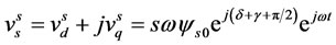
In order to obtain a qualitative understanding of the phenomena occurring in a synchronous motor during voltage sag, [7] performed a simplified theoretical analysis which we use for the symmetrical type. Prior to the sag, the motor is assumed to operate at steady state. The stator flux is given as follows:
 (1)
(1)

Figure 1. Phasor diagram of voltage sag types for s = 0.5.
where  is Flux linkage in stationary reference frame,
  and
and  are d and q components of flux linkages in stationary reference frame respectively,
  is the modulus of the stator flux linkage prior to the sag, δ is the load angle of the motor and γ is the angle between stationary and rotor reference frames. Here, the superscript s denotes stationary reference frame.
3.1. Symmetrical Voltage Sag (Type A)
The stator voltage vector leads the flux linkage by 90, and the magnitude is reduced due to sag. The remaining voltage vector can thus be written as follows:
 (2)
(2)
where  is the stator voltage in stationary reference frame in complex coordination,
  and
and  are d and q components of stator voltages in stationary reference frame, s is the voltage sag magnitude (based on the definition 0.1 < s < 0.9) and ω is the synchronous angular velocity.
The flux change can be obtained by integrated from voltage during the sag:
 (3)
(3)
The resulting flux vector is thus obtained by adding the change to the initial value. This results in equation (4).
 (4)
(4)
To find the stator flux in the rotor reference frame, we use:
 (5)
(5)
where  is flux linkage in rotor reference frame. Performing the transformation yields equation (6), which is constituted by a constant term and a term rotating in negative direction.
 (6)
(6)
Constant term in equation (6) has been multiplied by s, shows that the steady state flux is decreased due to the voltage sag.
Since we neglected the stator resistance, rotating term magnitude in equation (6) has been constant. But in fact, it is decrease as shown in Figure 2.

Figure 2. Flux trajectory in rotor coordination for symmetrical voltage sag (type A). (a) 2 cycles; (b) 2.25 cycles; (c) 2.5 cycles.
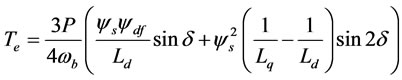
Rotating term makes flux oscillatory in q and q direction that consequently creates torque oscillations according to torque equations (7) and (8).
 (7)
(7)
 (8)
(8)
where  and
and  are d and q are components of stator currents in rotor reference frame, P is the number of poles,
  is the base angular frequency,
  is the flux linkage with the field winding and
 ,
,  are d and q axes inductances respectively. From equation (6) it is obvious that the stator flux will change substantially during on cycle in the rotor reference frame. These flux changes will give rise to inevitable torque pulsations. If the duration of the sag be a multiple of the period-time of the supply, the term
  in equation (6) equals to unity and the flux will be as same as the initial value. As a conclusion If the duration of the sag of type A be a multiple of the period-time of supply, the flux will has minimum distance to the initial value, therefore torque transients when the voltage magnitude is restored will be minimum.
On the other hand, if the duration of the voltage sag is half a period plus any number of full periods of the supply, the term  in equation (6) equals to –1 and the stator flux when the voltage is restored is given by:
 (9)
(9)
Since the voltage is restored, the voltage vector can be written as:
 (10)
(10)
By performing the same manipulations, the flux variation in the rotor reference frame is given by:
 (11)
(11)
The last equation, similar to equation (6), has a rotating term with fundamental frequency but the rotating term has twice the amplitude after the restoration of the voltage. Consequently, if the duration of the voltage sag is half a period plus any number of full periods of the supply, the flux has maximum distance to the initial value, therefore torque transients when the voltage is restored will be maximum.
Flux trajectory during sag for sag type A is a circle that its radius decreases (Figure 2). The center of this circle is a point which is determined from equation (6).
3.2. Unsymmetrical Voltage Sags
For other voltage sag types, voltage equations in two axes coordinate include sinusoidal terms with twice fundamental frequency therefore these terms affect the flux trajectory, besides mentioned transient. Voltage equations of voltage sag in rotor reference frame can be expressed as follows:
 (12)
(12)
where θ = ωt, and X(s) and Y(s) are functions of s.
The Voltage equations in complex coordination expressed as follows:
 (13)
(13)
By multiplying equation (13) in , voltage equation in stator reference frame is given by:
 (14)
(14)
The term  is similar to the right term of equation (2). With performing pervious steps, the resulting flux can be obtained as follows:
 (15)
(15)
We integrate from  in equation (14) to obtain the flux variation caused by this term in stator reference frame and by multiplying in
 ; the final equation for flux variation caused by this term in rotor reference frame is given by:
 (16)
(16)
X1(s) and Y1(s) are new obtained coefficients. The resulting flux in rotor reference frame can be obtained by summation of equations (15) and (16):
 (17)
(17)
The equation (17) consists of a constant term and two rotating term that the velocity of one of them is twice of another. The resultant of these three terms indicates the flux trajectory. Figure 3 shows the flux trajectory for different sag types with sag duration of 2, 2.25, and 2.5 cycles.
For sag types B and D, during sag, flux turns two circles in any period-time that its radius is smaller and constant. Therefore torque transients have twice the supply frequency. If the duration of these voltage sags be a multiple of half a period of the supply, the flux will be the same as the initial value at voltage restoration moment, therefore torque transients when the voltage is restored is not significant. Whereas, if the duration of these voltage
 (a) Type B
 (b) Type C
 (c) Type D
 (d) Type E
 (e) Type F
 (f) Type G
Figure 3. Flux trajectory in rotor coordination for unsymmetrical voltage sag (types B, C, D, E, F, and G), for sag duration of 2, 2.25, and 2.5 cycles.
sag be a quarter of a period plus any number of half cycles of the supply, the flux has maximum distance to the initial value, therefore torque transients when the voltage is restored will be maximum.
Flux trajectory for sag types C, E, and G detours from the circle, caused by terms with twice the supply frequency. This distortion appears in torque oscillations too. For these types, the effect of sag duration on peak torque at the voltage restoration moment is as same as type A.
For sag type F, flux trajectory distortion is the severest and a small circle appears in large circle turns in opposite direction. Nevertheless, the influence of sag duration on peak torque when the voltage restores is similar to sag types B and D.
4. Simulation
In order to observe the responses, a salient-pole 4150 kVA synchronous machine is modeled using generalized Park model [10] in MATLAB/SIMULINK based on [11], and different types of voltage sags with s = 0.5 are applied to it. The machine model details can be found in [10]. The motor parameters and rated quantities are given in Appendix B.
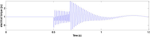
Before voltage sag, the machine consumes 1 pu real power in nominal terminal voltage at unity power factor. In t = 0.5 s, sag begins by changing motor terminal voltages. During voltage sag, load torque and excitation voltage are assumed to be constant. Figure 4 shows electrical torque, for type A voltage sag with duration of 10, 10.25, and 10.5 cycles.
As we expect, there is damped torque pulsation with supply frequency during and after voltage sag and the worst case for peak torque when voltage amplitude restores occurs when sag duration equals (0.5 + n)T, that T

(a) Sag duration = 10 cycles

(b) Sag duration = 10.25 cycles

(c) Sag duration = 10.5 cycles
Figure 4. Electrical torque for type A voltage sags with duration of (a) 10; (b) 10.25; and (c) 10.5 cycles.
is supply period-time.
Since the results for types B and D are identical, we only represented the curves for type B in Figure 5. The curves show that there are undamped torque oscillations during voltage sag. In this case, the worst peak torque occurs for a voltage sag with a duration of (2n + 1)T∕4.
Figure 6 shows the results for voltage sag of type C. It is observed that the torque curve has been deformed based on flux deformation. Like type A, the torque transient when the voltage is restored will be maximum, when the duration of voltage sag is a multiple of the period-time of the supply plus half a cycle.
For type F, the flux trajectory in complex coordination was different from other types. As we see in Figure 7, torque oscillations have been more deformed similar to its flux trace. Whereas in this case, the effect of the sag duration on the torque peak at the voltage recovery moment is almost as same as type B.
The difference will be more obvious when we change the sag duration and plot peak torque after restoring voltage magnitude as in Figure 8. In the case of type B voltage sag, peak torque changes sinusoidal respect to sag duration with a frequency twice the supply frequency that certificates last results. But for type F, it has a periodic form that has two local minimum per cycle, originnate from inner circle and outer circle in the flux trajectory. Whereas, its maximums occur at the durations similar to type B.
5. Conclusions
The effects of different sags types on the synchronous machine torque transient have been studied by the flux

(a) Sag duration = 10 cycles

(b) Sag duration = 10.25 cycles

(c) Sag duration = 10.5 cycles
Figure 5. Electrical torque for type B voltage sags with duration of (a) 10; (b) 10.25; and (c) 10.5 cycles.
trajectory analysis. In the analysis, the sag magnitude and the point of voltage wave that sag begins are not included.
Varying flux trajectory as sag type varies, the torque pulsation during and after voltage sag will be different. For sags types A, C, E, and G, if the duration of sag be a multiple of the period-time of the supply plus a half cycle, the peak torque at the voltage restoring moment will be maximum. For types B and D, if the duration of sag be a quarter of a period plus any number of half cycles of the supply, peak torque when the voltage is restored will be

(a) Sag duration = 10 cycles

(b) Sag duration = 10.25 cycles

(c) Sag duration = 10.5 cycles
Figure 6. Electrical torque for type C voltage sags with duration of (a) 10; (b) 10.25; and (c) 10.5 cycles.

(a) Sag duration = 10 cycles
(b) Sag duration = 10.25 cycles

(c) Sag duration = 10.5 cycles
Figure 7. Electrical torque for type F voltage sags with duration of (a) 10; (b) 10.25; and (c) 10.5 cycles.
 (a) For sag of type B
  (b) For sag of type F
Figure 8. Peak torque when voltage magnitude restores vs. sag duration for voltage sags of type B and F.
maximum. For sag type F, the relation between peak torque and sag duration is different, but its worst case for peak torque is as same as types B and D.
With obtained results we can identify the fault types that have the more intensive effect on the machine. After considering motor behavior against torque pulsations, the preventive decision can be made, Such as changing the transformer or load connections to change the voltage sag type or changing protective relays settings to prevent unessential tripping or damage to the shaft.
REFERENCES
- B. W. Kennedy, “Power Quality Primer,” McGraw-Hill, New York, 2000.
- R. C. Dugan, M. F. McGranaghan, S. Santoso and H. W. Beaty, “Electrical Power systems Quality,” 2nd Edition, McGraw-Hill, New York, 2004.
- C. Sankaran, “Power Quality,” CRC Press LLC, New York, 2002.
- IEEE Standard, “IEEE Recommended Practice for Monitoring Electric Power Quality1159-1995,” Institute of Electrical and Electronics Engineers, New York, 1995.
- M. H. J. Bollen, “IEEE tutorial on Voltage Sag Analysis,” IEEE Press TP139-0, New York, 1999.
- J. Arrillaga, M. H. J. Bollen and N. R. Watson, “Power Quality Following Deregulation,” Proceedings of the IEEE, vol. 88, No. 2, 2000, pp. 246-261. doi:10.1109/5.824002
- F. Carlsson, H.-P. Nee and C. Sadarangani, “Analysis of Peak Torque of Line-Operated Synchronous Machines Subjected to Symmetrical Voltage Sags,” International Conference on Power Electronics, Machines and Drives, 4-7 June 2002, pp. 480-485. doi:10.1049/cp:20020164
- J. C. Das, “Effects of Momentary Voltage Dips on the operation of induction and Synchronous Motors,” IEEE Transaction on Industry Applications, vol. 26, No. 4, 1990, pp. 711-718. doi:10.1109/28.55998
- M. H. J. Bollen, “Understanding Power Quality Problems: Voltage Sags and Interruptions,” IEEE Press, New York, 2000.
- P. C. Krause, O. Wasynczuk and S. D. Sudhoff, “Analysis of Electric Machinery,” 2nd editon, Wiley, New York, 2002.
- C. M. Ong, “Dynamic Simulation of Electrical machinery, Using Matlab/Simulink,” Prentice Hall, Upper Saddle River, 1998.
- F. Carlsson, “Explanation to Irregularities in the Dependence between Voltage Sag Magnitude and the Tripping Level for Line Operated Synchronous Machines,” Industry Applications Conference, Salt Lake City, 12-16 October 2003, pp. 1085-1062.
Appendix A
For symmetrical sags, the magnitude of sag is the remained RMS voltage in per unit or percent of rated voltage that expressed by “s”. For unsymmetrical sags, “s” is a coefficient that appears in voltage equations and causes difference in their magnitude and/or phase angles. Voltage equation for phase “a” at sag occurrence moment is as . Voltage equations for different sag types in synchronous frame are expressed as:
Type A:
 (A.1)
(A.1)
Type B:
 (A.2)
(A.2)
Type C:
 (A.3)
(A.3)
Type D:
 (A.4)
(A.4)
Type E:
 (A.5)
(A.5)
Type F:
 (A.6)
(A.6)
Type G:
 (A.7)
(A.7)
Appendix B
Ratings and parameters of 4150 kVA synchronous motor are stated in Table B1 [12].

Table B1. Rated data and parameters of synchronous machine.