World Journal of Nuclear Science and Technology
Vol.10 No.01(2020), Article ID:96522,14 pages
10.4236/wjnst.2020.101002
Design and Analysis of a Metallic Uranium Reactor Type-Pump Using the Magnesiothermy Process
Munir Dides, José Hernández*, Luis Olivares
Chilean Nuclear Energy Commission (CChEN), Santiago, Chile

Copyright © 2020 by author(s) and Scientific Research Publishing Inc.
This work is licensed under the Creative Commons Attribution International License (CC BY 4.0).
http://creativecommons.org/licenses/by/4.0/


Received: September 18, 2019; Accepted: November 19, 2019; Published: November 22, 2019
ABSTRACT
This paper shows a methodology to obtain metallic uranium through a magnesiothermy process. Chile has two experimental reactors operated by the “Chilean Nuclear Energy Commission” (CCHEN). One is 5 MW and the other is 10 MW. In order to fulfill international agreements about nuclear energy for testing purposes of these reactors, CChEN purchased 19.9% enriched uranium hexafluoride, also known as the limit of Low Enriched Uranium (LEU). Due to the capacity of these reactors, they need high-density uranium compounds for their fuel, in order to work with LEU. For this reason, the uranium needs a previous conversion into metallic uranium. The conversion laboratory carried out experiences for reduction of UF4 with Mg. The main purpose of this study was to analyze the operating conditions under which the reduction reaction takes place, the designed method and the equipment and materials used. The raw material used was dehydrated UF4, prepared by electrolytic reduction and commercial purity Magnesium. The reaction took place in a cylindrical reactor made of low alloy steel, with a conic section in the lower part. The internal zone was coated with a 2.5 cm thick layer of CaF2. The process started by applying external heating, according to a heating program, developed specially for this purpose. The reduction reaction took place starting at 650˚C. The result was a cylinder of uranium metal and MgF2 slag. The crossed cut uranium cylinder showed a smooth and homogeneous surface without inclusions of slag, pores or blisters. The yield of the reaction was of the order of 75% with respect to the expected theoretical value. The uranium cone obtained fulfilled the required conditions for source material for nuclear fuel fabrication, with a uranium content of 97.5%.
Keywords:
Magnesiothermy, Metallic Uranium, Heat Balance

1. Introduction
In the decade of the 80s, the Chilean Nuclear Energy Commission (CChEN) bought LEU in form of UF6. The objective of this purchase was the development of U3O8 fuel type compounds for these reactors. However, enrichment reduction international program (RERTR) launched in 1978, affected the continuity of this project, because U3O8 uranium compound allows limited uranium load. For this reason, CChEN needed to convert UF6 (LEU) into metallic uranium, suitable for the manufacture of higher neutron density fuels. This fact allowed using higher density compound, as U3Si2. Uranium and silicon form several different stoichiometric compounds including USi2, USi (or U34Si34.5), U3Si2, U3Si [1] [2]. The uranium density and thermophysical properties of high uranium content uranium silicides (U3Si2 and U3Si) make them an attractive material from both an economic and safety point of view as a replacement for UO2 [3]. Experience from research uranium fuel reactors indicate that U3Si exhibits too much swelling under irradiation for use as a nuclear fuel. Additionally it decomposes into U3Si2 and solid solution U above 900˚C, which is below some expected temperatures in uranium silicide fueled pins. Fortunately, U3Si2 has a very promising behavior under irradiation in research reactor fuels and maintains several advantageous properties over UO2. U3Si2 have 17% more uranium atoms in a set volume than in the same volume of UO2, given a constant percentage of theoretical density for both samples. This superior uranium loading has the potential to enable power uprates, extend cycle length in LWRs, or reduce enrichment, all of which are economically beneficial [4]. This fact raised the need to conduct studies to determine the most favorable conditions, by which uranium metal is prepared.
The literature mentions that the methodology to obtain metallic uranium consists in reducing, by exothermic reaction, UF4 with a metal, specifically Mg or Ca granules, according to the pre-established operating conditions [5]. This reaction takes place in a closed reactor in an inert atmosphere. The most common method to obtain UF4 is through the following chemical reactions [6]:
• Direct reduction of UO3 with H2 or other organic reducer to obtain UO2.
• Hydrofluoration of UO2 in fluidized bed with HF at a temperature between 450˚C and 480˚C.
• Electrolytic reduction of the U6+ ions to U4+ and its precipitation with F1− ion, or Reduction of the U6+ ions with SnCl2.
The remaining methods are feasible to be used to reach UF4 directly. The hydrolysis reaction of UF6 that takes place is: [7]
(1)
In the UO2F2 compound, the uranium ion has its highest oxidation state valence (U6+). Therefore, a reduction process transforms it into tetravalent uranium (U4+). An electrolysis process or reduction with stannous chloride achieves this process [8]. For this stage of the study, the raw material was uranium tetrafluoride prepared by electrolysis. This method of preparation consists in obtaining a synthetic solution of UO2F2 from the solubility of UO3 depleted with HF. According to the following reaction: [9]
(2)
The electrolysis process is based on the following ionization reaction:
(3)
The overall reaction that takes place in the electrolysis cell is as follows:
(4)
Or what is the same
(5)
Magnesiothermic reduction employs metallic magnesium or calcium as a chemical reducer of uranium. Magnesium is mixed with stoichiometric excess to uranium tetrafluoride (UF4), according to the following reaction:
(6)
UF4 is a greenish substance which, mixed with magnesium, can be reduced to uranium metal under adequate thermal conditions. This reaction is intensely exothermic. The reaction products utilize the resulting exothermic heat and melt to form the uranium ingot at the bottom of the crucible and the slag. The supernatant slag, which contains essentially MgF2, solidifies at the top of the ingot.
According to other authors, reaction (6) starts at 600˚C - 650˚C [10]. However, this heat generated must be enough to reach the melting reaction products; starting from room temperature, since U melts at 1132˚C and MgF2 at 1255˚C. To have a proper separation between uranium and slag, the molten products need a viscosity low enough to allow the breakup between them. The Effect of impurities, such as magnesium or uranium oxides, has been found to yield poor slag-metal separation probably due to incomplete reduction and high viscosity of oxide slag [11].
Another important aspect of this process is the presence of humidity and acid coming from the aqueous obtaining process The presence of H2O or HF leads to evolution of hydrogen by pre-reaction during heating at lower temperatures itself (380˚C - 600˚C), according to the following reactions: [11]
(7)
(8)
(9)
(10)
(11)
For this reason, it is very important to eliminate both water and acid traces before the beginning of the reaction, along with a preheating of the reactants before the reaction for this process [12].
2. Reactor Design Based on Heat and Mass Balance
The experience of reducing UF4 with Mg was carried out in a pump-type reactor, which was constructed of low alloy steel, with an effective volume of 30.000 cc. Initially the mass of UF4 was 4500 g . and the amount of Mg corresponds to the stoichiometric plus 20% excess. The electric oven heated the reactor using an electric oven of 5.5 kW of power. Three resistors distributed the heat, two located on the sides and the third at the bottom. A programmer regulated the power supply and temperature. Figure 1 shows the system used for the experience.
To prevent undesirable oxidation reactions in the dehydrated UF4-Mg mixture, the powders were contained in an inert atmosphere to remove water from both humidification and crystallization before their use in the process of reduction to metallic uranium. The X-ray diffraction analysis (DRX) of Figure 2 shows that the material used is dehydrated UF4, with a water level that does not affect the reduction reaction. In this case, the inert gas removed the humidity before the reduction process started.
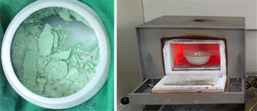
The UF4 pellet diameter, about 1.5 to 2 mm, was prepared via an electrolysis of uranyl fluoride (UO2F2) solution. The pellets was filtered to obtain the related crystals. The natural moisture from the aqueous obtainment process belongs to the uranium tetrafluoride lattice. To eliminate it, a drying furnace (Figure 3), heated at 150˚C with a ceramic crucible, eliminated the water of crystallization. The Mg was also dried as a precaution for possible adhered moisture.
The final temperature reached by the system once the reaction finished, was calculated based on the specific heat and reaction heats, including heat losses. According to these calculations, the melt temperature should reach 1450˚C. This temperature allowed obtaining a fluid slag, which in turn allows the reduced U
Figure 1. Schematic view of the reactor type pump. Measures in mm.
Figure 2. X-Ray Diffraction of the UF4 compound.
Figure 3. UF4 crystals sample—Drying furnace.
to decant. The reaction is exothermic and produces 82 kcal per mol formed, once it reaches the indicated temperature.
To determine the degree of preliminary preheating, the reactor needs to achieve the reaction conditions for the spontaneous reaction. The system needs a preliminary thermal balance. Table 1 shows the values used for the estimation of heat needed for the initial heating. Table 2 shows the heat requirement for the products obtained by reaction (6).
Table 3 shows the heat generated by reaction (6) and the requirement to melt the products obtained, U + MgF2, plus the excess heat. This heat is necessary for a good separation of U from the MgF2 slag.
The reactor at the beginning of the test contained 4500 g of UF4, equivalent to 12.74 moles. In these conditions, reaction (6) formed 25.48 moles of MgF2. The temperature expected inside the pump is around 1450˚C. At this temperature, the U formed melts and decant at the bottom of the reactor. The final state of the slag, MgF2 in this case, and U at this temperature are both liquid. Table 4 shows estimations for the specific heat of the uranium and the MgF2 slag, in their molten state.
Table 1. Thermodynamic data used for the heat balance in the final products for the proposed system.
Table 2. Heat involved in the reduction reaction (6) per compound.
Table 3. Heat produced by reaction (6).
Table 4. Heat available for the molten mixture of U + MgF2.
However, the balance also considered a yield of 90% for reaction (6). For a 90% UF4 conversion, the heat available to reach 1450˚C is the following.
Considering this criterion, Table 5 shows the estimation for the specific heat of the molten mixture of U + MgF2 to reach this temperature:
The value of 56.2 Cal/g˚C is the closest estimation for the expected results of this experience. At the proposed temperature, the U + MgF2 mixture has a viscosity low enough to allow the separation during the process.
3. Experimental Development
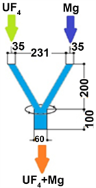
The trouser mix system of Figure 4 mixed the dried and dehydrated UF4 product with 20% Mg excess, for 40 min. at 16 R.P.M.
Figure 5 shows the reactor user for the test, including the heating system, the insulation and the argon inlet and outlet:
For insulation inside the reactor, the walls were covered with CaF2 technical grade, under 180 μm before filling the reactor with the mixture. The density of the compacted mixture is 3 g /cc approximately. With the reactor loaded, the argon cylinder connecting to the pump generates an inert atmosphere to prevent
Table 5. Estimation of the specific heat for U + MgF2 in molten state.
Figure 4. Schematic diagram of the trouser system. Measures in mm.
Figure 5. Magnesiothermy reactor.
the oxidation of the reactants, as undesirable reactions [13]. The argon inside the pump evacuates the air inside. Finally, the argon outlet sent the air to a water column to maintain a positive pressure, equivalent to 1500 mm water column. This positive pressure prevents the entry of gases from the outside. With this pressure achieved, the heating program started through the oven. The reaction started after 16 hrs and at a temperature of 620˚C - 650˚C.
To know the temperature at which the reaction begins, the differential thermal analysis (DTA) from Figure 6, determined that the required temperature for the uranium reduction is between 600˚C - 650˚C. Over this temperature, reaction (6) provides the required heat for the reaction.
The noise produced and the temperature increase confirmed the start of the reaction. At this point, the temperature control system shutdown the power
Figure 6. Heating curve for the proposed reactor.
supply to the oven, allowing it to cool freely by natural convection. After 24 hours, the reactor was disassembled and the load removed.
4. Results Obtained
According to the heat and mass balance, the reaction starts when the outside temperature of the oven reaches 650˚C. The proposed system obtains it after 21 hours.
The start of the reaction showed the following phenomenon:
• Heavy noise and vibrations.
• Increased pressure in the reactor pressure gauge and the argon flow regulator. This parameter reached a maximum value of 15 psig.
• Sudden temperature increase, up to the range of 1350˚C - 1400˚C.
Figure 7 shows the start of the pump-type reactor, once the reduction reaction started, at 650˚C:
With this phenomenon detected, the control system turned the oven off and allowed to cool freely until the next day. Table 6 shows the obtained products.
The reaction step lasted 12 hours. At this time, the argon gas flow was stopped because the slag formed in the process prevented the oxidation of the obtained uranium. The cooling was by natural convection, during a period of 16 hours before opening the reactor. The following figures show the aspects observed in the obtained product. Three aspects are highlighted: a porous area within the insulating material, is attributed to gases present during the process that come from moisture not previously removed at the beginning, or decomposition of some loaded product.
Another area corresponds to a dense and compact material immediately after the reactor wall, is CaF2, used as insulating material.
Figure 8 shows the main product obtain at the end of the process. This figure shows 3 clearly different zones. In the upper part, the Mg-U-slag mixture. The medium zone had the main MgF2 slag portion. And finally, in the bottom, a uranium billet of high density. The following figures show the main aspects of the obtained products.
Table 6. Products obtained for the process.
Figure 7. Magnesiothermy reactor, once the reduction reaction started.
Figure 8. Schematic view of the cross section of the metallic U and the MgF2 slag.
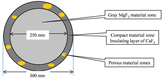
Figure 9 shows the porous zone inside the insulating material. These zones result in heat losses during the pre-heating and the metallothermic reaction process. This aspect consider the 10% of heat loss during the reduction reaction.
Figure 10 shows the uranium obtained at the bottom of the reactor and the MgF2 slag at the end of the process. The conic form of the billet allows obtaining a homogeneous final product and the separation from the undesired material. Another important aspect is the empty space during the cooling time. The geometry assured that the contraction suffered by the slag do not reach the uranium billet. In this case, leaving a space of 100 cm. between the slag and the billet.
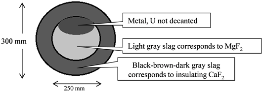
Figure 11 shows the presence of a portion of metallic uranium during the slag removal. Despite having reached the temperature to reach the molten state, its viscosity was not enough for a correct separation, causing the entrapment inside the slag.
Figure 9. Schematic view from the elevation of the slag and the insulation system.
Figure 10. Schematic view of the side of the reactor.
Figure 11. Schematic picture of the superior view of the elevation.
5. Chemical Analysis
Table 7 shows the compositions of the products formed inside the reactor.
Table 8 shows the chemical analysis of the compounds of the reactor and the contamination of every part with residual uranium
Table 8 shows a high uranium content of impurities in the sample coming from the external insulating material. This was because of the high pressure exerted by the energy produced by the reduction reaction. Figure 12 shows disassembly of the reactor and the obtained uranium billet:
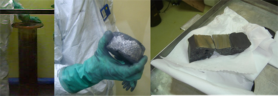
It is worth noting that the appearance of the uranium button does not show pores, blisters or inlays inside. This indicates that there was no trapped slag inside the product of interest or the temperature was low at some interior point. It
Table 7. Properties of the obtained products.
Table 8. Chemical analysis of the obtained products.
Figure 12. Uranium ingot obtained and cross-section of the sample.
presents a smooth, even and uniform fracture that indicates a total fusion and above the melting temperature of the U. This confirms that the system reached the indicated temperature of 1300˚C, according to what the system needs to reach the fusion of the U and its total runoff to the bottom of the reactor. Table 9 shows the chemical composition of the uranium product obtained.
For the reactor tests, the most important impurities in the uranium are boron and cadmium. In this case, the normal content of these impurities should be less than 1 ppm (or µg/g), because of their capacity of neutron absorption during the uranium fuel burning tests. The cadmium and boron levels are appropriate. Other important impurities are oxygen and nitrogen. Their presence was because the insulation conditions were not enough to prevent its oxidation.
The absence of UF4 in the slag indicates that the reaction was total or in a percentage of the order of 90% to 95%. The X-ray diffraction diagram indicated the presence of UF5 that may correspond to material trapped in the insulating material. The control of the atmosphere and the overpressure allowed maintaining a constant pressure throughout the experience and prevented most of the oxidation of the initial components. Maintaining the same heating power through time guaranteed a constant temperature profile, with a minimum difference between center and edges. This allowed developing the reaction (6) through the entire reactor. The initial yield of the process achieved a value of 76%. This proves that the system reached the temperatures according to what is needed to reach the fusion of the U to the bottom and the MgF2 slag to the top of the reactor.
Table 10 shows the experimental results obtained during the experience.
However, Table 11 shows the results using the consideration of a 90% yield for the degree of progress of the reaction:
The difference between the 76% recovery achieved in the billet shown in Figure 5 and the theoretical 90% used for the calculations is because of the uranium trapped in the molten MgF2 slag and the CaF2 insulator. In the case of the uranium in MgF2, this happened because this section did not reached the fusion temperature needed to produce the separation. In the case of the insulator, the uranium was trapped because of the high pressure of reaction (6). According to Table 11, the initial estimation of the specific heat value of 56.2 cal/g˚C for the U + MgF2 mixture proved to be adequate and adjusted to what happened in the experience
6. Conclusions
The main conclusions of this study are the following:
1) The proposed system allowed obtaining metallic uranium as a final product,
Table 9. Result of the chemical analysis performed on the U obtained.
Table 10. Temperature reached by the solid products.
Table 11. Temperature reached by the solid products, with 90% of reaction efficiency.
with a yield of the order of 76%. The chemical analysis showed a uranium content of 90% - 95% and a level of impurities that allowed producing high-density uranium compounds for Chilean research reactors.
2) The temperature conditions reached allowed the fusion of U and MgF2 slag. These conditions separated the desired uranium product from the slag. The system achieved temperatures of 1433˚C.
3) The design of the reactor based of thermodynamic considerations of specific heat and latent heat of fusion for the metallic uranium and the MgF2 slag, for the total mass of the compounds is consistent with the results obtained in the experience.
Conflicts of Interest
The authors declare no conflicts of interest regarding the publication of this paper.
Cite this paper
Dides, M., Her- nández, J. and Olivares, L. (2020) Design and Analysis of a Metallic Uranium Reactor Type-Pump Using the Magnesiothermy Pro- cess. World Journal of Nuclear Science and Technology, 10, 9-22. https://doi.org/10.4236/wjnst.2020.101002
References
- 1. Hutchin, R.A. (2015) A New Physical Model for the Vacuum Field Based on Einstein’s Stimulated Emission Theory. Optics and Photonics Journal, 5, 109-112. http://dx.doi.org/10.4236/opj.2015.54009
- 2. Hutchin, R.A. (2015) A Local Theory of Entangled Photons That Matches QM Predictions. Optics and Photonics Journal, 4, 304-308. http://dx.doi.org/10.4236/opj.2014.410030
- 3. Barrow, J.D. and Tipler, F.J. (1986) The Anthropic Cosmological Principle. Oxford University Press, Oxford.
- 4. A. J. Faria , H. M. França , G. G. Gomes , R. C. Sponchiado (2006) The vacuum electromagnetic fields and the Schrodinger picture. arXiv:quant-ph/0510134 v2
- 5. Casimir, H.B.G. (1948) On the Attraction between Two Perfectly Conducting Plates. Proc. Kon. Nederland. Akad. Wetensch. B51, 793-795.
- 6. Bordag, M., Mohideen, U. and Mostepanenko, V.M. (2001) New Developments in the Casimir Effect. Physics Reports, 353, 1-205. http://dx.doi.org/10.1016/S0370-1573(01)00015-1
- 7. Einstein, A. (1917) Zur Quantentheorie der Strahlung (On the Quantum Theory of Radiation). Physika Zeitschrift, 18, 121-128.
- 8. Clauser, J.F. (1974) Experimental Distinction between the Quantum and Classical Field-Theoretic Predictions for the Photoelectric Effect. Physical Review D, 9, 853. http://dx.doi.org/10.1103/PhysRevD.9.853
- 9. Adler, R., Basin, M. and Schiffer, M. (1965) Introduction to General Relativity. McGraw-Hill, Boston.
- 10. Hutchin, R.A. (2015) Universal Cross-Section of Photonic Interaction. Optics and Photonics Journal, 5, 109-112. http://dx.doi.org/10.4236/opj.2015.54009
- 11. Snelgrove, J.L. and Domgala, R.F. (1987) The Use of U3Si2 Dispersed in Aluminum in Plate-Type Fuel Elements for Research and Test Reactors. ANL/RERTR/TM-11, Argonne National Lab, IL. https://doi.org/10.2172/5688807
- 12. Vaugoyeau, H., Lombard, L. and Morlevat, J. (1972) A Contribution to the Study of the Uranium-Silicon Equilibrium Diagram. Atomic Energy of Canada Limited, 39, 323-329. https://doi.org/10.1016/0022-3115(71)90153-X
- 13. Okamoto, H. (1990) Si-U (Silicon-Uranium). de Binary Alloy Phase Diagrams, II Ed., T.B. Massalski, 3374-3375.
- 14. Harp, J.M., Lessing, P.A. and Hoggan, R.E. (2015) Uranium Silicide Pellet Fabrication by Powder Metallurgy for Accident Tolerant Fuel Evaluation and Irradiation. Inaho National Laboratory (INL), 1-5. https://doi.org/10.1016/j.jnucmat.2015.06.027
- 15. Reilly, D., Athon, M., Corbey, J., Leavy, I., McCoy, K. and Schwantes, J. (2018) Trace Element Migration during UF4 Bomb Reduction: Implications to Metal Fuel Production, Worker Health and Safety, and Nuclear Forensics. Journal of Nuclear Materials, 510, 156-162. https://doi.org/10.1016/j.jnucmat.2018.07.052
- 16. Silva Neto, J., Urano de Carvalho, E., Lazzari Garcia, R., Saliba-Silva, A., Gracher Riella, H. and Durazzo, M. (2017) Production of Uranium Tetrafluoride from the Effluent Generated in the Reconversion via Ammonium Uranyl Carbonate. Nuclear Engineering and Technology, 40, 1711-1716. https://doi.org/10.1016/j.net.2017.07.019
- 17. Agency, I.A.E. (1994) Properties of UF6 and Other Uranium Compounds. de Manual on Safe Production, Transport, Handling and Storage of Uranium Hexafluoride, IAEA, Vienna, 11-20.
- 18. Da Silva Neto, J. (2008) Processo alternativo para obtenção de tetrafluoreto de uranio a partir de efluentes fluorados da etapa de reconversão de uranio. Instituto de pesquisas energéticas e nucleares, Sao Paulo.
- 19. Cordfunke, E.H.P. (1969) The Chemistry of Uranium. Elsevier Publishing Company, Petten.
- 20. Yemel’Yanov, V.S. and Yevstyukhin, A.I. (2013) The Metallurgy of Nuclear Fuel: Properties and Principles of the Technology of Uranium, Thorium and Plutonium. Elsevier, Oxford.
- 21. Mayekar, S., Singh, H., Meghal, A. and Koppiker, K. (1985) Magnesio-Thermic Reduction of UF4 to Uranium Metal: Plant Operating Experience. Uranium Extraction Division, B.A.R.C., Trombay, Bombay.
- 22. Harper, J. and Williams, A. (1957) Factors Influencing the Magnesium Reduction of Uranium Tetrafluoride. Extraction and Refining of Rarer Metals, 143-162.
- 23. Durazzo, M., Saliba-Silva, A., Martins, I.C., Urano de Carvalho, E.F. and Riella, H.G. (2017) Manufacturing Low Enriched Uranium Metal by Magnesiothermic Reduction of UF4. Annals of Nuclear Energy, 110, 874-885. https://doi.org/10.1016/j.anucene.2017.07.033


