Journal of Electromagnetic Analysis and Applications
Vol. 2 No. 9 (2010) , Article ID: 2764 , 6 pages DOI:10.4236/jemaa.2010.29067
Analysis of Auxiliary Winding Effect on the Leakage Inductance Reduction in the Pulse Transformer Using ANSYS
![]()
1Islamic Azad University, Shahre Ghods Branch, Tehran, Iran; 2 Islamic Azad University, Tehran North Branch, Tehran, Iran; 3Islamic Azad University, Ashtian Branch, Ashtian, Iran.
Email: {aqukh, m_pedram_razi, hfeshki}@yahoo.com
Received July 20th, 2010; revised August 18th, 2010; accepted August 18th, 2010
Keywords: Auxiliary Windings, Leakage Inductances, Finite Element Method and ANSYS
ABSTRACT
Several applications need high voltage and low rise time pulses that increasing of the voltage level can be done by using transformer. The rise time is increased because of transformer leakage inductance. One of the methods to decrease the rise time is using auxiliary windings between primary and secondary. In this paper, one type of pulse transformer included auxiliary windings is modeled and simulated in ANSYS software. In this study, at first the transformer has been simulated without auxiliary windings and the leakage and self inductances are obtained then the auxiliary windings are considered in the model to calculate the leakage and self inductances of the transformer. Simulation results can be used to investigate the effect of auxiliary winding on the leakage inductance.
1. Introduction
High-voltage pulses are often obtained from a pulse generating circuit driving a high-voltage pulse transformer. The large number of turns in the secondary windings and also insulation gap between layers of winding and windings increase the leakage inductance of pulse transformers. The rise time of high voltage pulse is depending on the leakage inductance. Many applications, such as medical, technology and military need high-voltage fast rising pulses. This requires efficient and flexible pulsed power circuits with optimization of all components [1-5]
However, if the leakage inductance in the high-voltage pulse transformer needs to be reduced, two subtractive connected windings can be added to the transformer. If these windings are fitted with the same number of turns, the electromotive force generated in the auxiliary windings is due only to the primary and secondary leakage flux. The current across them produces a magnetic field reducing only the leakage flux and, therefore, the leakage inductance in the transformer [6-8]. The most attractive winding configuration for high voltage, the core-type transformer with primary and secondary on different core legs, is seldom used in pulsed application, because of its weak magnetic coupling between windings, which would result in a slow-rising output voltage pulse. The exceptional improvement achieved in the output pulse shape of high-voltage core-type transformer, with separated primary and secondary, fitted with two auxiliary windings, for plasma immersion ion implantation applications, where almost rectangular negative high-voltage pulses are used to bias a plasma-immersed target to achieve conformal ion implantation [9].
To contribute to a better understanding of transformer operation with auxiliary windings, a mathematical model based on the theory of electromagnetic coupled circuits [10]. Alongside the new design methods [11], [12] used today to manufacture high-voltage pulse transformers using the latest materials, a common way to overcome the problems caused by parasitic elements is to use resonant topologies [12-14]. Finite element simulation is a robust method to calculation flux and inductance leakage. So a high voltage pulse transformer was modeled and simulated with ANSYS software in this paper. At first the pulse transformer is simulated without auxiliary windings and then with auxiliary windings. The inductance is calculated with energy method. The simulation results show the decreasing of leakage inductance with using the auxiliary windings.
2. Transformer Mathematical Equations with Auxiliary Windings [9]
The structure of four windings transformer is shown in Figure 1.
Using the Faraday’s induction law in each winding, neglecting the distributed capacitances of the windings, yields
 (1)
(1)
where the subscript:
i: Refers to the index of the winding v: The instantaneous terminal voltage i: The instantaneous current
Ψ: The instantaneous flux linkage e: The induced instantaneous voltage R: The effective resistance The average flux linkage is written as:
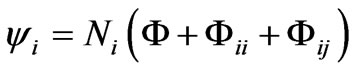 (2)
(2)
That is divided into three main components.
Φ: The resultant flux, linking all the windings
Φii : The self-flux of the winding
Φij: The mutual flux between pairs of windings The linkage flux for the primary winding is defined as:
 (3)
(3)
The equation (3) can be rewritten as:
 (4)
(4)
where the subscript lii is Self inductance and lij is Mutual inductance. According to (1) and (3) the instantaneous terminal voltage at primary winding is the sum of the winding resistance voltage drop, the induced electromotive force due to the time varying resultant flux, and induced electromotive forces associated with the self and mutual leakage fluxes.
 (5)
(5)

Figure 1. The circuit of mathematical model of a transformer with four windings [9].
As shown in Figure 2, the auxiliary windings of transformer are connected in subtractive mode (terminals 5 and 6 are connected to terminals 7 and 8, respectively). Considering that  and
and  in Figure 2, applying to (5) and taking into consideration that
 , yields,
 (6)
(6)
Also Equations (7) to (9) for other three windings are derived like Equation (6) respectively.
 (7)
(7)
 (8)
(8)
 (9)
(9)
In this connection  which yields
 (10)
(10)
The current across the auxiliary windings is ruled by (10). It is interesting to observe that  is independent of the time derivative of the resultant flux, Ф. If the auxiliary windings have the same number of turns,
  exists only as the consequence of the leakage coupling between the primary and secondary leakage flux linking the auxiliary windings.
The auxiliary current, function of the leakage flux coupling between the primary and secondary with the third and fourth windings, generates a magnetic flux that reduces the
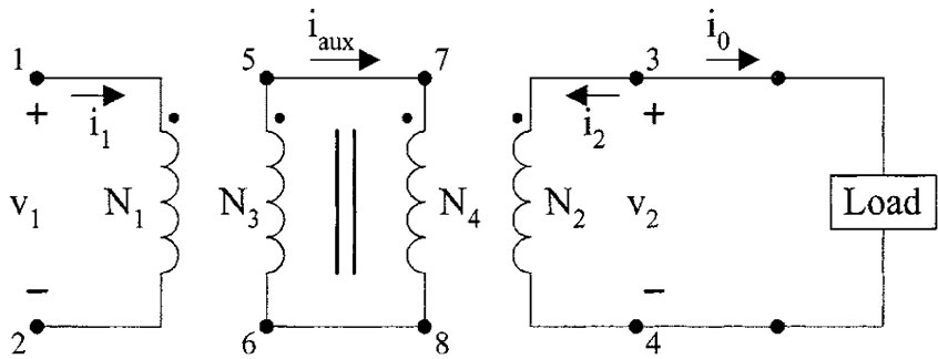
Figure 2. Schematic representation of the transformer with loaded secondary,  and the two auxiliary windings connected in subtractive mode
 and
and [9].
[9].
leakage flux of the primary and secondary windings. Consequently, the leakage inductance in the transformer is reduced. The resultant flux, Ф, is not affected by the auxiliary windings.
3. Finite Element Analysis of Transformer
To evaluate the effects of auxiliary windings on the leakage inductances reduction, a pulse transformer with auxiliary windings is modeled in ANSYS software. ANSYS is a finite element analysis (FEA) code widely used in the computer-aided engineering (CAE) field. It is powerful software to analyze the magnetic energy with finite element method. The leakage and magnetic inductances are function of the stored energy in the window of pulse transformer and in the core of pulse transformer respectively. The current density is needed to simulate the magnetic and leakage flux of pulse transformer (as loads). So the current density is applied to windings area. The potential is equal to zero in boundary and it is considered as boundary condition. At first the pulse transformer is simulated without using the auxiliary windings and then the auxiliary windings is considered in simulation to reach desired results.
The pulse transformer modeled in ANSYS is shown in Figure 3. Primary winding includes two 25 turns’ layers in window of pulse transformer. The dimension of each layer of primary winding is 34 mm × 1.5 mm. The line spacing between two layers is 0.1 mm that the electric insulation is found in this space. The line spacing between the primary and third windings is 0.1 mm and it is 0.1 mm between the third winding and the main leg of the pulse transformer.
The secondary winding is 500 turns in eight layers. The line spacing between secondary and auxiliary (forth)
windings is 0.1 mm. The width of each layer of secondary

Figure 3. The model of pulse transformer with auxiliary windings.
winding is 0.5 mm and because the layers length isn’t equal so the mean length of layers is 25 mm.
Two auxiliary windings, with 25 turns in one layer, are shown in Figure 3. The length of third auxiliary winding is 34 mm and its width is 0.5 mm. The dimension of forth winding is the same as third winding. Core type of pulse transformer is ferrite (high frequency) with 10 kHz nominal frequency. The B-H curve of ferrite core is shown in Figure 4.
4. Simulation of Pulse Transformer without the Auxiliary Windings
The leakage inductances of primary and secondary windings are calculated without the effects of auxiliary windings. The energy method is used to calculate leakage inductance that is explained in following.
4.1. Calculation of Magnetic and Leakage Inductances of the Primary Winding
In this case, the current density is just applied to primary winding, and then the magnetic stored energy in the pulse transformer is obtained.
The stored magnetic energy in the transformer is shown in Figure 5. According to this figure, the total stored energy in the transformer is equal to 104.348 J for one meter of depth. But the depth of the modeled transformer is 0.007m, so the total stored energy in transformer is 0.730436J (104.348 × 0.007). Distribution of magnetic energy in each element of the core is shown in Figure 6. Also by attention to this figure, the total stored energy in the core is 104.319J for 1 meter of depth and so for 0.007 m of depth, the stored energy will be 0.730233J. The self primary inductance can be obtained from Equation (11).
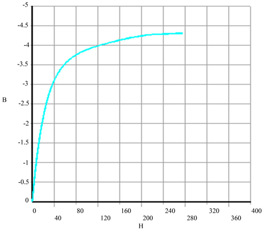
Figure 4. ferrite core B-H curve of pulse transformer.

Figure 5. The energy distribution in the whole model elements and total magnitude of saved energy.

Figure 6. The energy distribution in the core elements and magnitude of saved energy (just core).
 (11)
(11)
Leakage inductance can be calculated by using the difference between the stored energy in the transformer and the core.
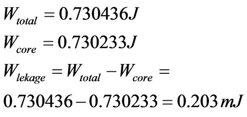 (12)
(12)
The leakage energy is 0.203mJ for 7 mm depth. According to Equation (11), the leakage and self inductances are equal to 1.8 µH and 6.5 mH respectively.
4.2. Calculation of Magnetic and Leakage Inductances of Secondary Winding
Similar to primary winding, the transformer and core stored energy are obtained from simulation and the secondary self and leakage inductances are calculated that they are 645mH and 273 µH respectively. The self and leakage inductances of primary and secondary windings without auxiliary windings are listed in Table 1.
5. Simulation of Primary Winding with Third Auxiliary Winding
In this case, the auxiliary windings are connected in deferential mode and the inductances are obtained.
5.1. Simulation of Primary Winding of Pulse Transformer with Third Auxiliary Winding
To simulate the flux leakage of pulse transformer with auxiliary windings, two current densities are applied to primary and third auxiliary winding, then the stored energy in transformer and the core is obtained which is shown in Figure 7 and Figure 8 respectively.

Figure 7. Distribution and total magnitude magnetic energy in depth unit of model.
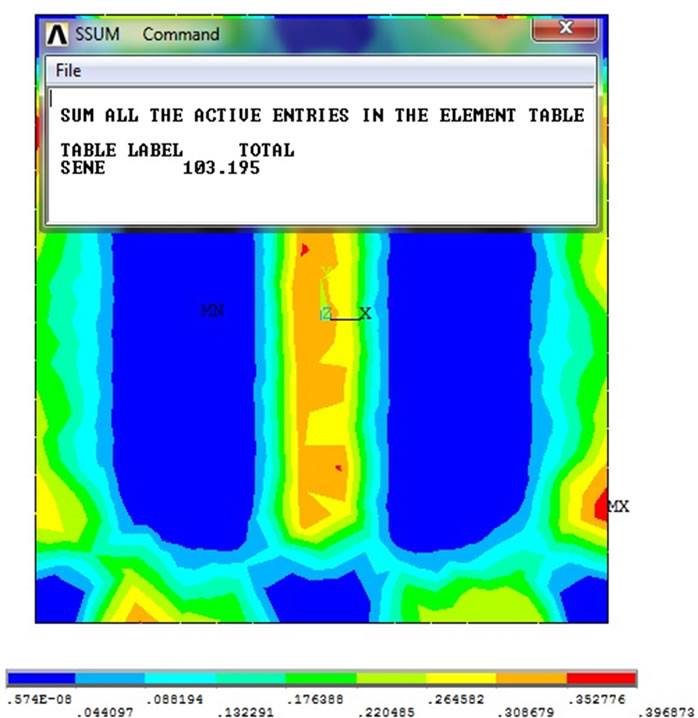
Figure 8. Distribution and magnitude saved energy in core at unit depth.
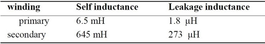
Table 1. The magnetic and leakage inductances of primary-secondary windings without auxiliary windings.
The energy stored in the transformer and core for 1 m depth are 103.217 J and 103.195 J respectively which for the 0.007 m of core depth are 0.722519 J and 0.722365 J respectively. Using the stored energy value and Equation (11), the self primary inductance is 6.42 mH and the leakage inductance is 1.37 µH.
5.2. Simulation of Secondary Winding of Pulse Transformer with Forth Auxiliary Winding
The current direction of auxiliary windings is opposite to main windings (primary and secondary winding), so the direction of the current density in secondary winding is opposite to that of the forth auxiliary winding. As a result, the opposite flux density of forth auxiliary winding is the main reason of flux density reduction of secondary winding that it leads to the leakage inductance reduction.
The self inductance of secondary winding is calculated equal to 640 mH, and also total leakage energy in this case is 0.000217 J. Therefore, the leakage inductance is obtained equal to 193 µH. The self and leakage inductances of pulse transformer with auxiliary winding is shown in Table 2.
6. Conclusions
In this paper, the effect of auxiliary windings used in a pulse transformer is investigated. The auxiliary windings were placed in proximity of primary and secondary windings. It has been shown that the auxiliary current, iaux function of the leakage flux coupling between the primary and secondary with the third and fourth windings, generates a magnetic flux that reduces the leakage flux of the primary and secondary windings. Consequently, the leakage inductance in the transformer is reduced. The resultant flux, Ф, is not affected by the auxiliary windings. To this aim, a pulse transformer with auxiliary windings was modeled in ANSYS software. At first, the simulation has done without using of auxiliary windings and then the auxiliary windings were added to the transformer model. By using the obtained result from

Table 2. The magnetic and leakage inductances of primary-secondary windings with auxiliary windings.
the first case (without auxiliary windings), the primary and secondary leakage inductances are calculated equal to 1.8 µH, 273 µH respectively. In second case (with auxiliary windings), the primary and secondary inductances are reduced to 1.36 µH, 193 µH respectively. The result shows that the self inductances don`t considerably change in two cases of simulations.
7. Acknowledgements
This paper is extracted from the research project as title: "Design, Simulation and Construction of Low Rise Time High-Voltage Pulse Transformers Using Auxiliary Windings" in Islamic Azad University, Shahre Ghods Branch.
REFERENCES
- Y.-H. Chung and C.-S. Yang, “All Solid-State Switched Pulser for NO Control,” 36th IEEE Industry Applications Conference, 30 September-4 October 2001, Vol. 4, 2001, pp. 2533-2540.
- N. Grass, W. Hartmann and M. Romheld, “Microsecond Pulsed Power Supply for Electrostatic Precipitators,” 36th IEEE Industry Applications Conference, 30 September-4 October 2001, Vol. 4, 2001, pp. 2520-2524.
- J. Jethwa, E. E. Marinero and A. Muller, “Nanosecond Rise Time Avalanche Transistor Circuit for Triggering a Nitrogen Laser,” Review of Scientific Instrument, Vol. 52, No. 7, 1981, pp. 989-991.
- M. P. J. Gaudreau, T. Hawkey, J. Petry and M. A. Kempkes, “A Solid State Pulsed Power System for Food Processing,” Pulsed Power Plasma Science, Digital Techniques Papers, Vol. 2, 2001, pp. 1174–1177.
- Y. C. Cheng, K. Ping, X. Tian, X. Wang, B. Tang and P. Chu, “Special Modulator for High Frequency, LowVoltage Plasma Immersion Ion Implantation,” Review of Scientific Instrument, Vol. 70, No. 3, 1999, pp. 1824-1828.
- A. M. Pernía, J. M. Lopera, M. J. Prieto and F. Nuño, “New Family of ZVS QRC and MRC with PWM Control Based on Magnetic Elements Modification,” European Power Electronics EPE Journal, Vol. 8, No. 12, 1999, pp. 25-32.
- A. M. Pernía, J. M. Lopera, M. J. Prieto and F. Nuño, “Analysis and Design of A New Constant Frequency Control for QRC and MRC Based on Magnetic Elements Modification,” IEEE Transactions Power Electronics, Vol. 13, No. 2, 1998, pp. 244-251.
- L. M. Redondo, E. Margato and J. F. Silva, “Low-Voltage Semiconductor Topology for Kv Pulse Generation Using a Leakage Flux Corrected Step-Up Transformer,” Proceedings of IEEE Power Electronics Specialists Conference, 2000, pp. 326-331.
- L .M. Redondo, E. Margato and J. F. Silva, “Rise Time Reduction in High-Voltage Pulse Transformer Using Auxiliary Windings,” IEEE Transactions Power Electronics, Vol. 17, No. 2, 2002, pp. 196-206.
- L. M. Redondo, J. F. Silva and E. Margato, “Pulse Shape Improvement in Core-Type High-Voltage Pulse Transformers with Auxiliary Windings,” IEEE Transactions Magnetics, Vol. 43, No. 5, 2007, pp. 1973-1982.
- M. H. Kheraluwala, D. W. Novotny and D. M. Divan, “Coaxial Wound Transformers for High-Power HighFrequency Applications,” IEEE Transactions Power Electronics, Vol. 7, No. 1, 1992, pp. 54-62.
- M. García, C. Viejo, M. Secades and J. González, “Design Criteria for Transformers in High Voltage Output, High Frequency Power Converter Application,” European Power Electronics EPE Journal, Vol. 4, No. 4, 1994, pp. 37-40.
- J. Kein and M. Padberg, “A Modular Low-Cost, HighVoltage Pulse Generator that is Highly Effective in Terms of Pulse Energy and Repetition Frequency,” Measurement Science Technology, Vol. 6, No. 5, 1995, pp. 550-553.
- J. M. Sun, S. P. Wang, T. Nishimura and M. Nakaoka, “Resonant Mode PWM DC-DC Converter with a HighVoltage Transformer-Link and its Control Methods for Medical-Use X-Ray Power Supply,” Proceedings of 8th European Conference of Power Electronics Applicant, Lausanne, Switzerland, 7-9 September 1999, Proc. on CD-ROM.