Journal of Software Engineering and Applications
Vol. 5 No. 2 (2012) , Article ID: 17473 , 11 pages DOI:10.4236/jsea.2012.52009
Application of a Computational Tool to Study the Influence of Worn Wheels on Railway Vehicle Dynamics
![]()
IDMEC, Instituto Superior Técnico, Technical University of Lisbon, Lisbon, Portugal.
Email: jpombo@dem.ist.utl.pt
Received November 22nd, 2011; revised December 27th, 2011; accepted January 10th, 2012
Keywords: Wear Prediction Software; Steel Wheel Profile; Vehicle-Track Interaction; Wheel-Rail Contact Forces
ABSTRACT
The search for fast, reliable and cost effective means of transport that presents better energy efficiency and less impact on the environment has resulted in renewed interest and rapid development in railway technology. To improve its efficiency and competitiveness, modern trains are required to travel faster, with high levels of safety and comfort and with reduced Life Cycle Costs (LCC). These increasing demands for vehicle requirements imposed by railway operators and infrastructure companies include maintaining the top operational speeds of trainsets during their life cycle, having low LCC and being track friendly. This is a key issue in vehicle design and in train operation since it has a significant impact on the safety and comfort of railway systems and on the maintenance costs of vehicles and infrastructures. The purpose of this work is to analyze how the wear progression on the wheelsets affects the dynamic behavior of railways vehicles and its interaction with the track. For this purpose a vehicle, assembled with new and worn wheels, is studied in realistic operation scenarios. The influence of the wheel profile wear on the vehicle dynamic response is assessed here based on several indicators used by the railway industry. The running stability of the railway vehicles is also emphasized in this study.
1. Introduction
To improve the efficiency and competitiveness of railway transport with respect to other means of transportation it is necessary, among others, to minimize the damage on vehicles caused by the track conditions and to decrease the infrastructure deterioration due to the trains operation. This is an important and very sensitive issue in the railway industry due to the economical impact on the vehicles maintenance and on the life cycle costs of tracks. As a consequence, there is a growing tendency to define the track access charges, i.e. the prices billed by the infrastructure managers to the railway operators, according to the damage that the trainsets operation is supposed to cause to the tracks. It is, therefore, essential to acquire a better understanding on the factors influencing the wear progression on the rolling stock and the repercussions of such deterioration on the loads transmitted to the infrastructure.
During the design phase of a new railway system one of the most important issues that arises is the optimization of the dynamic behavior of railway vehicles and the construction features of the infrastructure. Due to their complexity and multidisciplinarity, these studies require the use of advanced computational tools. These tools must be able to characterize and predict the performance of the vehicles by using reliable and validated mathematical models. In addition, they should be able to represent accurately the railway infrastructure, including the track geometry and its irregularities. The use of such tools is of paramount importance to reduce the costs, the time and the risks associated with the development of new railway vehicles and to refine the construction features of the novel infrastructures. During the design stage of the project, the numerical tools allow to perform several simulations, under various scenarios, and to test the performance of the different mechanical and structural solutions in order to reach an optimized design. Furthermore, analysis can be carried out to evaluate the impact of design changes or failure mode risks in a much faster and less costly way than the physical implementation and test of those changes in real systems. Computational tools with such characteristics can also be used to support the improvement of existing rolling stock, by proposing optimized solutions for vehicles in order to minimize the wear evolution and/or the vehicle-track interaction forces. In addition, these tools can be used to enhance existing tracks by helping scheduling the track maintenance procedures and by identifying the levels of track irregularities that promote the increase of wear and/or the loads developed between the vehicles and the infrastructure.
An important railway research topic is to assess the impact of the wheel wear growth on the dynamic response of trainsets and on their interaction with the infrastructure. In the literature, several approaches to estimate wheel and rail wear using dynamic simulations are available [1-12]. However, less emphasis has been placed on the consequences of that wear on the performance of the railway vehicles.
The work reported by Nielsen et al. [13] focuses on the train-track interaction and mechanisms of irregular wear. These authors discuss the causes, consequences and suggest solutions to minimize the problems for several types of wheel and rail wear. Hur and co-workers [14] use a 1/5 scaled roller rig bogie prototype to analyze the influence of the wheel profile wear on the running stability (critical speed) of railway vehicles. Fröhling [15] addresses the asymmetric wheel profile wear and analyses the consequential damages to the wheels, rails, turnouts and bogie components. Wu [16] discusses the effects of wheel and rail profiles on vehicle curving and lateral stability through the evaluation of the North American freight railways wheel profile. Fergusson and co-workers [17] tackle the wheel wear problem in another perspective. They present a methodology to minimize the wheel wear by optimizing the primary suspension stiffness and the centre plate friction of a self-steering three-piece bogie without compromising the vehicle stability.
In this text, a software is applied to study the impact of wheel wear on the dynamic behavior of railway vehicles and on the corresponding loads transmitted to the track. The strategy consists of assembling a vehicle with wheels having new and worn profiles and performing comparative studies in realistic operation scenarios. The vehicle dynamic performance is assessed based on several indicators, namely: 1) wheelsets motion; 2) non-compensated lateral acceleration; 3) loads imposed to the infrastructure and; 4) derailment coefficient Y/Q. The running stability of the railway vehicles is emphasized in the studies carried out here and conclusions are set regarding the influence of the wear growth on equivalent conicity.
The work presented here resulted from the joint research effort between ALSTOM Ferroviaria (IT), University of Sheffield (UK) and Instituto Superior Técnico (PT), developed in the scope of the Project AWARE (ReliAble Prediction of the WeAr of Railway WhEels). This project was funded by the EU and aimed to develop a computational tool able to study, according to the trainset operation conditions, the wear evolution on railway wheels. The objective was to improve the modeling capabilities of the softwares used to study the dynamic response of railway systems in order to enhance the wheel wear prediction techniques.
2. Description of the Software
The software used in this work allows to study the dynamic behavior of railway vehicles and to predict the wear evolution of wheel profiles. It consists of using the commercial multibody software VAMPIRE [18], which is used to study the dynamics of the railway vehicles, integrated with a purpose-built wear computation module that is used to predict the wear of railway steel wheels [6,8,10, 19].
The commercial software uses a multibody formulation to simulate the dynamic performance of integrated railway systems that include the vehicle, the track and the wheel-rail contact interaction [18]. This approach allows simulating the vehicle, including the masses and inertias of the structural elements and the characteristics of suspensions. It is also possible to represent accurately the track geometry. The vehicle-track interaction is studied through a wheel-rail contact formulation that is used to compute the normal and tangential forces.
The wear computational module is a purpose-built code [6,8,10,19]. That is used to manage the preand postprocessing dynamic analysis data in order to compute the wheel profiles wear for a given railway system. The strategy consists of providing an initial profile to the wheels of the trainset and to use the commercial multibody software to run a dynamic analysis for a pre-defined travel distance. Then, the wear computation block collects the necessary data from the dynamic analysis results and calculates the wear, i.e., the amount of material to be removed from the wheel surfaces. The resulting updated profiles are then used as input for a new railway dynamic analysis. This methodology, represented in Figure 1, is repeated as many times as required by the user in order to be representative of the real operation conditions of the railway vehicle.
The core of the wear prediction procedure is the wear computation that calculates the amount of worn material to be removed from the wheel surfaces. This block is divided into 3 parts: 1) Contact model; 2) Wear function; 3) Wear distribution. The contact model processes the dynamic analysis results to obtain the wheel-rail contact parameters [20-24]. The wear function uses these contact parameters as input to compute the quantity of worn wheel material [5-7,19]. The wear distribution removes the quantity of worn material from the wheel profiles.

Figure 1. Outline of the wear prediction software.
More specifically, the wear functions relate the energy dissipated in the wheel-rail contact patch with the amount of worn material to be removed. In general, these wear laws use the normal and tangential forces and the relative slip velocities (creepages), as input to compute the wear. In the literature [5-7,19,25-35] different methods for estimating wear of railway wheels can be found. These methods are based on real wear data acquired using different experimental techniques.
In this work, the wear function developed by the University of Sheffield [6,19] is used. It relates the wear rate, representing the weight of lost material (mg) per distance rolled (m) per contact area A (mm2), to the product Tg, where T is the tangential contact force and g is the global creepage. This formulation is based on twin disk experimental data acquired from the contact between discs made of R8T wheel material and UIC60 900A rail material, which are the ones used to assemble the vehicles and tracks considered here. These experimental tests have identified three wear regimes, mild, severe and catastrophic. The equations governing the University of Sheffield wear function are defined in Table 1. The detailed description of the wear computation module is outside the scope of this text, the interested readers are referred to the works [6,8,10,19].
3. Wear Parameters
The identification of a common method for wheel wear geometric analysis is essential during trainset operation. The purpose is to monitor periodically some geometrical parameters of the wheel profiles in order to check if they are within the admissible intervals. When the limit values are reached, it means that the wheels have to be re-profiled.
A good and pragmatic approach for wheel wear characterization is based on the profile parameters Sd, Sh and qR [36], which are represented in Figure 2, where Sd is the flange thickness, Sh is the flange height and qR represents the flange slope quota. The wheel wear representation based on programmed measurements of these geometrical parameters is widely used by the railway industry. Such assessment is a relevant criterion to evaluate the wear state of the wheels and to schedule the re-profiling procedures.

Table 1. Equations governing the wear function.
The measurement of the wear parameters Sd and qR allows predicting the consequences of the wheel profiles wear on the dynamic behavior of the railway vehicles. For example, the flange thickness Sd is very important as it limits the lateral clearance of wheelset with respect to the track, which influences the vehicle stability. The flange slope quota qR is also an important parameter. If it is too small, the wheel flange will be almost vertical, which implies that the transitions (switches crossing) and the flange contacts will occur abruptly. Such a situation causes very high contact forces that damage both vehicle and infrastructure.
4. Operation Scenario
4.1. The Track
The railway tracks are composed of straight sections, transition curves and circular curves. When travelling in curves, the railway vehicles are influenced by centrifugal forces, which act in a direction away from the center of the curve and tend to overturn the vehicles. In order to counteract this force, the outer rail in a curve is raised. The difference of height between the two rails is called cross level offset h (or cant). According to this construction features, the height of the track centerline in a curve is designated as vertical offset ZO. These two parameters are represented in Figure 3.
In the software used here, the track layout is defined by the following design parameters [18]: 1) plan view curvature; 2) vertical offset; and 3) cross level offset. The plan view curvature c represents the curvature of the track in the horizontal plane, being defined as:
 (1)
(1)

Figure 2. Wheel wear parameters.

Figure 3. Cross level and vertical offset.
where R is the radius of the curve.
The track considered for the dynamic studies conducted in this work corresponds to the first 3500 m of the railway network between the Italian cities of Cuneo and Ventimiglia. The track layout, represented in Figure 4, is composed of a straight segment L1 followed by two left circular curves L3 and L5, with radii R1 and R2 respectively. Then, the track continues with a tangent segment L7 that is followed by a right curve L9, with a radius R3, and finalizes with a straight segment L11.
When trains are operated at normal speeds, a circular curve with cant cannot be followed directly by a tangent track, and vice-versa [37-39]. A transition between these two types of segments, designated by transition curve, is required in order to guarantee the curvature continuity and to minimize the variation of lateral accelerations on vehicles. Usually, the radius of a transition curve is changed continuously, decreasing from an infinite value, at the tangent end, to a radius equal to that of the circular curve, at the other end. The transition curves are also used between circular curves with different radii. In Figure 4 the track segments L2, L4, L6, L8 and L10, represented with dashed lines, are transition curves.
Also the cant is changed gradually over the transition length, leading to the so-called superelevation ramp. It represents the cant variation along the transition, ensuring a smooth cant evolution from a null value, at the straight track, to the nominal cant of the circular curve. The design characteristics of the track depicted in Figure 4 are represented in Table 2. In the studies conducted here, no track irregularities are considered. The readers interested in analyzing the influence of the track irregularities on the wheel wear growth and on the vehicle-track interaction loads are referred to work [11].

Figure 4. Track representation.
4.2. The Vehicle
The trainset considered for the studies conducted here is a non-articulated conventional trainset composed of seven vehicles interconnected by linking elements, as represented in Figure 5. In this trainset, the two compositions in both extremities are motor, whereas the three middle coaches are trailer.
Due to the trainset configuration, it is assumed that, concerning the studies performed here, the dynamic behavior of each vehicle has a non-significant influence on the others. According to this assumption, each vehicle of the trainset can be studied independently, as shown in Figure 6. In this way, the vehicle model considered is composed only by one unit of the trainset. This vehicle is a motor unit that is assembled with two trailer wheelsets, represented in white in Figure 6, and two motor wheelsets, represented in black.

Table 2. Characteristics of the track.

Figure 5. Non-articulated conventional trainset.
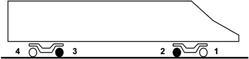
Figure 6. Motor vehicle of trainset.
The 3D model of the railway vehicle is build using a multibody approach [39-42]. This methodology allows representing accurately the mass and inertia properties of the structural elements that compose the vehicle. It also includes the kinematic joints, which control the relative motion between the bodies, and the force elements, that represent suspension components of vehicle. The detailed description of the vehicle model is outside the scope of this text. The interested readers are referred to the work [9].
4.3. The Wheel-Rail Interaction
The wheel-rail contact model, considered in the railway dynamic analyses performed here, uses the fully nonlinear creep law from VAMPIRE tool [18], i.e., with nonlinear contact forces and non-linear contact geometry. The rail profile is a UIC 60 [43] with a rail inclination of 1/20 and the track gauge is 1435 mm. The wheel profile is a S1002 [36] with a flange-back spacing of 1360 mm, a wheel diameter of 890 mm and an axleload of 160 kN in normal load conditions.
4.4. Worn Wheel Profile
In order to assess how the dynamic behavior of a railway vehicle is influenced by the wheels wear, new and a worn wheel profiles are considered, as represented in Figure 7. Notice that both new and worn profiles are symmetrical.
The wear state of the wheel profiles can be evaluated using the geometrical parameters Sd, Sh and qR, which are defined in Figure 2. The values of these wear parameters, correspondent to the new and worn profiles depicted in Figure 7, are presented in Table 3.

Figure 7. New and worn wheel profiles.
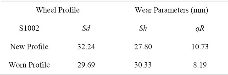
Table 3. Wear parameters for wheel profiles.
5. Comparison Study
The comparative study of the railway vehicle, assembled with new and worn wheels, is performed here. The purpose is to analyze several indicators in order to assess how the wheels wear growth influences the vehicle dynamic behavior. The vehicle velocity is 95 km/h, corresponding to the real service conditions of the trainset.
5.1. Running Stability
The equivalent conicity [37,44,45] is an important parameter used to evaluate the running stability of railway vehicles. The importance of this parameter results from the fact that the steering mechanism of a wheelset is not due to conicity or change in rolling radius of one wheel by itself, but due to the difference in rolling radii between left and right wheels. In fact, if a wheelset is moved laterally from a centred position, a difference in rolling radii arises. The equivalent conicity is defined as:
 (2)
(2)
where Dr is the instantaneous difference in rolling radii between left and right wheels and y is lateral displacement of the wheelset with respect to the centre position. Notice that, for a wheelset with straight cones, the equivalent conicity is equal to the conicity of its wheels.
In general, the equivalent conicity is a nonlinear function of the wheelset lateral displacement, especially for track gauges smaller than the nominal value. It is a function of the wheel and rail profiles as it depends on the geometric combination of both surfaces. It also depends on the wheelset inside gauge, flange thickness, rail cant and track gauge. Greater wheelset inside gauge and bigger flange thickness have the same influence as smaller track gauge, i.e. the lateral clearance decreases. In such cases, the contact point moves to the flanges for smaller lateral displacements and equivalent conicity increases.
The equivalent conicity is also affected by the wheel wear. In Figure 8, the evolution of the equivalent conicity for the wheelsets assembled with the new and worn wheels is presented.

Figure 8. Evolution of the equivalent conicity.
In order to guarantee the running stability of railway vehicles, the equivalent conicity should remain below 0.4 and, to ensure the centring effect of the wheelsets, it must be greater than 0.1 [44]. From Figure 8 it is observed that, for a wheelset lateral shift of 4 mm, the equivalent conicity has a value of 0.01 when considering the new wheel profile S1002, whereas for the worn profile it has a value of 0.064. These results show that the use of both profiles does not lead to problems regarding the vehicle stability. Nevertheless, the low values obtained in the tread zone mean that the wheelsets do not have a meaningful rolling radii difference between left and right wheels. This effect may originate a low gravitational stiffness, i.e., difficulties for the wheelsets to center themselves on the track, especially when the vehicle is assembled with new wheels.
The lateral displacement of the front wheelset with respect to the track centerline is shown in Figure 9. The results show that, when entering the curves, the wheelsets with new and worn wheel profiles are displaced laterally, towards the outer rail, as much as needed so that the difference in rolling radii corresponds to the difference in travelled length on outer and inner rails. Since no sufficient difference in rolling radii is achieved, the lateral displacement increases until being limited by the flange contact on the outer wheel. After reaching the flange, the lateral displacement remains constant during the curve negotiation. It can be observed that the flange clearance on the new wheelset is about 7 mm whereas, for the worn one, it is about 10 mm. These results are in agreement with the new and worn profiles depicted in Figure 7.
The results from Figure 9 also show that, in the tangent track segments after both left and right curves, both wheelsets present a low frequency lateral oscillation with decaying amplitude. This phenomenon is known in the railway industry as vehicle lower sway and it occurs when using new wheel profiles S1002 and rail profiles UIC 60 with 1/20 cant. In such conditions, the equivalent conicity of the wheelsets is very small, as demonstrated in Figure 8, and, consequently, after a perturbation the vehicle has more difficulty to center itself on the track.
It is also observed that, when using new profiles, the periodic lateral oscillations of the wheelset have higher

Figure 9. Running stability of the front wheelset.
amplitudes. This is due to its lower equivalent conicity, which originates a smaller gravitational stiffness and more difficulty for its self centering on the track. When using the worn wheels, the equivalent conicity is higher and the wheelset has a stronger tendency to return to the centred position. Notice that this lower sway movement of the railway vehicle does not raise safety issues as the oscillations decrease leading to a stable running.
5.2. Non-Compensated Lateral Acceleration
In curves, the railway vehicles are subjected to centrifugal accelerations, being its effect counteracted by the track cant, as shown in Figure 3. This solution reduces the perceived lateral acceleration when negotiating a curve and, consequently, the respective forces.
The Non-Compensated Acceleration (NCA), on a given body, represents the resultant lateral acceleration in a local referential that rotates with the body in the roll direction. With reference to Figure 10, the NCA is defined as the difference between the lateral components of the centrifugal acceleration aCarb and of the gravitational acceleration ag, being written as:
 (3)
(3)
where V is the vehicle velocity, R is the radius of the curve, j is the cant angle, ac is the centrifugal acceleration and g is the acceleration of gravity. According to this definition, the NCA represents the lateral acceleration felt by a passenger travelling in the carbody.
The equilibrium cant, for a given curve radius and vehicle speed, corresponds to the cross level offset that originates zero track plane acceleration. In general, the track curves are designed to have an equilibrium cant for the nominal velocity conditions of the vehicles that operate on that line. In such conditions, the vehicles produce a resultant vertical force through the centerline of the track, which originates the same vertical wheel-rail interaction forces on the left and right side. This is advantageous as maximum utilization of traction effort and minimum wear

Figure 10. Non-compensated lateral acceleration.
on wheels and rails can be realized [38]. Furthermore, neglecting the flexibility of the primary and secondary suspensions, the vehicles run with zero NCA which is advantageous for the passengers as they do not feel the centrifugal accelerations on curves.
Another concept that is important to introduce when studying the vehicle performance on curves is the notion of cant deficiency and cant excess, which are depicted in Figure 11. A railway vehicle is running with cant deficiency when the track cant is not sufficient to assure zero track plane acceleration. In this case, the NCA originates a resultant force FR pointing towards outside of the curve, the passengers are pushed in that direction due to the centrifugal force and the vertical contact forces are higher on the outer wheels of the wheelsets. In general, the maximum value allowed for the NCA in the carbody is 1 m/s2. Values above this one are considered uncomfortable for the passengers.
When, for a given curve radius and vehicle speed, the track cant is higher than necessary to guarantee zero track plane acceleration, it means that the railway vehicle is running with cant excess. In such situation, the NCA originates a resultant force FR pointing towards inside of the curve, the passengers are pushed in that direction due to the lateral component of the gravitational force and the vertical contact forces are higher on the inner wheels.
The NCA on the leading wheelset, front bogie and carbody are presented in Figures 12 and 13 for the railway vehicle assembled with new and worn wheels, respectively. Following the UIC 518 [46], these signals are post-processed with a low pass filter with a cut-off frequency of 1 Hz and 2 poles. It is observed that the wheels wear state does not influence the NCA in any of the structural elements that compose the vehicle.
5.3. Loads Imposed to the Infrastructure
The third indicator considered here to evaluate the influence of the wheels wear on the vehicle dynamic behavior is the loads imposed to the infrastructure. It is characterized by the wheelset ripage forces and by the vertical wheelrail contact forces. The ripage force FRipage represents the total lateral force transmitted to the track by a wheelsetbeing obtained as the sum of the lateral wheel forces exerted on the left and right rails. The ripage force is also known as track shift force since it is related to the risk of shifting the track laterally when a train passes. This force is represented in Figure 14 for the cases in which the vehicle is running on a straight track and negotiating a curve.
The ripage forces originated by the front and rear wheelsets of the railway vehicle are presented in Figures 15 and 16, respectively. These results have two steps of signal post-processing [46]. First, the lateral track forces data is processed with a sliding window 2 metre running average filter. Then, a low pass filter with a cut-off frequency of 20 Hz and 2 poles is used to obtain the final results for the ripage forces.


Figure 11. Cant deficiency and cant excess.

Figure 12. NCA with new profiles.

Figure 13. NCA with worn profiles.


Figure 14. Ripage and vertical forces on track.

Figure 15. Ripage forces on front wheelset.

Figure 16. Ripage forces on rear wheelset.
The comparison of Figures 15 and 16 reveals that, when the vehicle is assembled with worn wheels, the front wheelset originates slightly higher lateral track forces on curves than when using new profiles. On the other hand, the rear wheelset with worn wheels transmits lower ripage forces to the track than with new wheels.
The vehicle-track interaction loads are also characterized by the vertical contact forces on the left FL and right FR rails, as represented in Figure 14. The vertical forces on the front and rear wheelsets of the railway vehicle are presented in Figures 17 and 18, respectively. These results are defined in the local referential of the wheel-sets and are post-processed with a low pass filter with a cutoff frequency of 20 Hz and 2 poles [46].
The graphs from Figures 17 and 18 show that, when the vehicle is running in the curved sections of the track, the vertical contact forces on the outer wheels are higher than on the inner ones. These results indicate that the railway vehicle is running with cant deficiency in all curves of the track. In such conditions, and with reference to Figure 11, a resultant centrifugal force pointing towards outside of the curve arises, which implies that the vertical contact forces are higher on the outer wheels of the vehicle.
Figures 17 and 18 also allow comparing the vertical contact forces obtained with new and worn wheel profiles. In curve, the results of the front wheelset show that the wheels wear originate slightly higher vertical forces on the outer wheels and lower loads on the inner ones. On the rear wheelset, no differences are detected between the vertical contact forces obtained with new and worn wheel profiles.
5.4. Derailment Coefficient Y/Q
The resultant force acting at the wheel-rail contact area can be decomposed into longitudinal, lateral and vertical components. The ratio between the lateral Y and vertical Q components, represented in Figure 19, is referred to as the Y/Q ratio. This parameter is especially important in predicting the risk of flange climbing and of rail turnover [37,38]. Flange climbing, which is one common reason for derailment, means that the wheel flange climbs onto the top of the rail and continues rolling over the rail head. Usually it occurs in combination with flange steering in curve negotiation but it can also occur when the vehicle is running faster than its critical speed.

Figure 17. Vertical contact forces on front wheelset.

Figure 18. Vertical contact forces on rear wheelset.

Figure 19. Vertical and lateral components contact forces.
The criticalness of a given Y/Q ratio value is a function of the prevailing dynamic conditions. For example, Y/Q ratio values that represent a problem in high speed situations may not be so important in low speed conditions. In general, large steady-state lateral forces are accompanied by large vertical loads tending to keep the Y/Q ratios below critical levels. However, large Y/Q ratios can occur transiently as a result of sudden dynamic reductions in vertical loading.
In practice, an Y/Q ratio value in the range of 0.8 - 1.2 is generally considered as the minimum for wheel climb to be likely to occur [37,38]. This maximum allowed value is function of the friction coefficient and of the contact angle at the flange contact point. Values in excess of the double of these have been observed but, because of their short duration, wheel climb did not occur [38]. Therefore, the duration of the occurrence is also an important parameter when studying this issue.
The values of the Y/Q ratio in the wheels of the front and rear wheelsets of the railway vehicle are presented in Figures 20 and 21, respectively. These results have two steps of signal post-processing [46] First, the data is processed with a sliding window 2 metre running average filter. Then, a low pass filter with a cut-off frequency of 20 Hz and 2 poles is used.
The comparison of the graphs from Figures 20 and 21 show that the highest values of the Y/Q ratio occur on the right wheel of the leading wheelset, when it is running on the left curve of the track. This is in agreement with the results from Figure 9 where it is observed that, when entering the curve, the front wheelset is displaced laterally, towards the outer rail, until reaching flange contact on the right wheel. Notice that this higher value for the lateral force on the right wheel is also accompanied by a higher vertical force, as shown in Figure 17, which is a consequence of the vehicle running with cant deficiency. This combination of larger lateral force and higher vertical load tends to keep the Y/Q ratio below critical levels.
From Figures 20 and 21, it is also possible to compare the Y/Q ratio obtained with the railway vehicle assembled with wheels having new and worn profiles. The results show that, in the front wheelset, the Y/Q ratio is higher when using worn profiles. The opposite happens in the rear wheelset, where the larger values of the derailment coefficient occur when the wheelsets are equipped with new wheels.
6. Conclusions
In service, the wheels of trainsets are subjected to wear. When the worn state of the profiles reaches the limit values defined by the regulations, the wheels need to be reprofiled. For a better understanding and a wider assessment of the wheel wear phenomenon, it is important to tackle two issues: 1) Study the operation conditions that promote the wheel wear growth, and; 2) Evaluate the consequences of the changing wheel profiles on the dynamic behavior of the railway vehicles. The second problem is addressed in this work. For this purpose, a vehicle is assembled with wheels having new and worn profiles and a comparative study is made.
The running stability of the wheelsets reveals that, during curve negotiation, they are displaced laterally towards the outer rail. As no sufficient difference in rolling radii between left and right wheels is achieved, their lateral shift is only limited by the flange contact on the outer wheel. It is also observed that, when the vehicle is assembled with new wheelsets, the equivalent conicity is lower, which originates a smaller gravitational stiffness and more difficulty for the vehicle self-centring on the track, exhibiting a more pronounced lower sway motion.
The NCA are also studied here. The results reveal that the wheels wear state has a negligible influence on the NCA perceived on carbody, bogie frames and wheelsets of the vehicle.
The study of the influence that wheel wear growth has on the loads imposed to the infrastructure reveal that, when travelling on curves, the vehicle assembled with worn wheels originate higher ripage forces on the front wheelset. On the other hand, the rear wheelset with new wheels transmit larger lateral shift forces to the track.
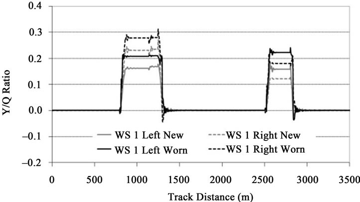
Figure 20. Y/Q ratio on front wheelset.

Figure 21. Y/Q ratio on rear wheelset.
The results obtained for the derailment coefficient Y/Q show that in the front wheelset the values are higher when using worn profiles. The opposite happens in the rear wheelset, where the larger values of the Y/Q occur when the wheelsets are equipped with new wheels. In all wheelsets, the values obtained for the Y/Q ratio are more than 50% below the critical levels.
7. Acknowledgements
The work presented here has been developed in the framework of the European Project AWARE (Reliable Prediction of the Wear of Railway Wheels). The project is supported by the European Community under the Sixth Framework Programme Marie Curie Actions: Host Fellowships, Transfer of Knowledge (TOK-IAP) with the contract number MTKI-CT-2006-042358.
The author also wants to gratefully acknowledge the collaboration and the valuable discussions had with Dr. Naim Kuka, Dr. Caterina Ariaudo and Dr. Riccardo Verardi from ALSTOM Ferroviaria (Italy).
The author was partially supported by the Portuguese Foundation for Science and Technology (FCT) through the Project WEARWHEEL (PTDC/EME-PME/115491/ 2009).
REFERENCES
- M. Ansari, I. Hazrati, E. Esmailzadeh and S. Azadi, “Wear Rate Estimation of Train Wheels Using Dynamic Simulations and Field Measurements,” Vehicle System Dynamics, Vol. 46, No. 8, 2008, pp. 739-759. doi:10.1080/00423110701586436
- J. Arizon, O. Verlinden and P. Dehombreux, “Prediction of Wheel Wear in Urban Railway Transport: Comparison of Existing Models,” Vehicle System Dynamics, Vol. 45, No. 9, 2007, pp. 849-874. doi:10.1080/00423110601149335
- A. Asadi and M. Brown, “Rail Vehicle Wheel Wear Prediction: A Comparison between Analytical and Experimental Approaches,” Vehicle System Dynamics, Vol. 46, No. 6, 2008, pp. 541-549. doi:10.1080/00423110701589430
- X. Jin, Z. Wen, X. Xiao and Z. Zhou, “A Nu-Merical Method for Prediction of Curved Rail Wear,” Multibody System Dynamics, Vol. 18, 2007, pp. 531-557. doi:10.1007/s11044-007-9073-3
- R. Lewis and R. Dwyer-Joyce, “Wear Mechanisms and Transitions in Railway Wheel Steels,” Journal Engineering Tribology, Vol. 218, 2004, pp. 467-478. doi:10.1243/1350650042794815
- R. Lewis, R. Dwyer-Joyce, U. Olofsson, J. Pombo, J. Ambrósio, M. Pereira, C. Ariaudo and N. Kuka, “Mapping Railway Wheel Material Wear Mechanisms and Transitions,” Institution of Mechanical Engineers, Part F: Journal of Rail and Rapid Transit, Vol. 224, No. 3, 2010, pp. 125-137. doi:10.1243/09544097JRRT328
- R. Lewis and U. Olofsson, “Mapping Rail Wear Regimes and Transitions,” Wear, Vol. 257, No. 7-8, 2004, pp. 721- 729. doi:10.1016/j.wear.2004.03.019
- J. Pombo, J. Ambrósio, M. Pereira, R. Lewis, R. DwyerJoyce, C. Ariaudo and N. Kuka, “A Railway Wheel Wear Prediction Tool Based on a Multibody Software,” Journal of Theoretical and Applied Mechanics, Vol. 48, No. 3, 2010, pp. 751-770.
- J. Pombo, J. Ambrósio, M. Pereira, R. Lewis, R. DwyerJoyce, C. Ariaudo and N. Kuka, “A Study on Wear Evaluation of Railway Wheels Based on Multibody Dynamics and Wear Computation,” Multibody Systems Dynamics, Vol. 24, No. 3, 2010, pp. 347-366. doi:10.1007/s11044-010-9217-8
- J. Pombo, J. Ambrósio, M. Pereira, R. Lewis, R. DwyerJoyce, C. Ariaudo and N. Kuka, “Development of a Wear Prediction Tool for Steel Railway Wheels Using Three Alternative Wear Functions,” Wear, Vol. 271, No. 1-2, 2011, pp. 238-245. doi:10.1016/j.wear.2010.10.072
- J. Pombo, J. Ambrósio, M. Pereira, R. Verardi, C. Ariaudo and N. Kuka, “Influence of Track Conditions and Wheel Wear State on the Loads Imposed on the Infrastructure by Railway Vehicles,” Computers and Structures, Vol. 89, No. 21-22, 2011, pp. 1882-1894. doi:10.1016/j.compstruc.2011.05.009
- M. Rosenberger, P. Dietmaier, J. Payer and K. Six, “The Influence of the Wheelset’ Relative Kinematics of Railway Vehicles on Wheel/Rail Wear in Curved Track,” Vehicle System Dynamics, Vol. 46, No. 1, 2008, pp. 403- 414. doi:10.1080/00423110801979242
- J. Nielsen, R. Lundén, A. Johansson and T. Vernersson, “Train-Track Interaction and Mechanisms of Irregular Wear on Wheel and Rail Sur-faces,” Vehicle System Dynamics, Vol. 40, No. 1, 2003, pp. 3-54. doi:10.1076/vesd.40.1.3.15874
- H. Hur, J. Park, W. You and T. Park, “A Study on the Critical Speed of Worn Wheel Profile Using a Scale Model,” Journal of Mechanical Science and Technology, Vol. 23, No. 10, 2009, pp. 2790-2800. doi:10.1007/s12206-009-0732-6
- R. Fröhling, “Analysis of Asymmetric Wheel Profile Wear and Its Consequences,” Vehicle System Dynamics, Vol. 44, No. 1, 2006, pp. 590-600. doi:10.1080/00423110600879296
- H. Wu, “Effects of Wheel and Rail Profiles on Vehicle Performance,” Vehicle System Dynamics, Vol. 44, No. 1, 2006, pp. 541-550. doi:10.1080/00423110600875393
- S. Fergusson, R. Fröhling and H. Klopper, “Minimising Wheel Wear by Optimising the Primary Suspension Stiffness and Centre Plate Friction of Self-Steering Bogies,” Vehicle System Dynamics, Vol. 46, No. 1, 2008, pp. 457-468. doi:10.1080/00423110801993094
- DeltaRail Group Ltd, “VAMPIRE Pro User Manual—V 5.02,” Derby, UK, 2006.
- N. Tassini, X. Quost, R. Lewis, R. Dwyer-Joyce, C. Ariaudo and N. Kuka, “A Numerical Model of Twin Disc Test Arrangement for the Evaluation of Railway Wheel Wear Prediction Methods,” Wear, Vol. 268, No. 5-6, 2010, pp. 660-667. doi:10.1016/j.wear.2009.11.003
- K. L. Johnson, “Contact Mechanics,” Cambridge University Press, Cambridge, 1985.
- J. J. Kalker, “Survey of Wheel-Rail Rolling Contact Theory,” Vehicle System Dynamics, Vol. 8, No. 4, 1979, pp. 317-358. doi:10.1080/00423117908968610
- J. J. Kalker, “Three-Dimensional Elastic Bodies in Rolling Contact,” Kluwer Academic Publishers, Dordrecht, 1990.
- J. Pombo and J. Ambrósio, “Application of a Wheel-Rail Contact Model to Railway Dynamics in Small Radius Curved Tracks,” Multibody Systems Dynamics, Vol. 19, No. 1-2, 2008, pp. 91-114. doi:10.1007/s11044-007-9094-y
- J. Pombo, J. Ambrósio and M. Silva, “A New WheelRail Contact Model for Railway Dynamics,” Vehicle System Dynamics, Vol. 45, No. 2, 2007, pp. 165-189. doi:10.1080/00423110600996017
- T. Beagley, “Severe Wear of Rolling/Sliding Contact,” Wear, Vol. 36, No. 3, 1975, pp. 317-335.
- J. Bolton and P. Clayton, “Rolling-Sliding Wear Damage in Rail and Tyre Steels,” Wear, Vol. 93, No. 2, 1983, pp. 145-165. doi:10.1016/0043-1648(84)90066-8
- F. Braghin, R. Lewis, R. Dwyer-Joyce and S. Bruni, “A Mathematical Model to Predict Railway Wheel Profile Evolution Due to Wear,” Wear, Vol. 261, 2006, pp. 1253- 1264. doi:10.1016/j.wear.2006.03.025
- Dearden, “The Wear of Steel Rails and Tyres in Railway Services,” Wear, Vol. 3, 1960, pp. 43-59. doi:10.1016/0043-1648(60)90174-5
- R. Enblom, “Simulation of Railway Wheel Profile Evolution Due to Wear,” Proceedings of the SIMPACK User’ Meeting, Baden-Baden, 21-22 March 2006.
- T. Jendel, “Prediction of Wheel Profile Wear—Comparisons with Field Measurements,” Wear, Vol. 253, 2002, pp. 89-99. doi:10.1016/S0043-1648(02)00087-X
- T. Meinders and P. Meinke, “Rotor Dynamics and Irregular Wear of Elastic Wheelsets, System Dynamics and Long-Term Behaviour of Railway Vehicles: Track and Subgrade,” In: K. Popp and W. Schiehlen, Eds., Springer, Berlin, 2002, pp. 133-152.
- T. Pearce and N. Sherratt, “Prediction of Wheel Profile Wear,” Wear, Vol. 144, No. 1-2, 1991, pp. 343-351. doi:10.1016/0043-1648(91)90025-P
- A. Ramalho, “A Geometrical Model to Predict the Wear Evolution of Coated Surfaces,” Wear, Vol. 264, No. 9-10, 2008, pp. 775-780. doi:10.1016/j.wear.2006.12.076
- A. Ramalho and J. Miranda, “The Relationship between Wear and Dissipated Energy in Sliding Systems,” Wear, Vol. 260, No. 4-5, 2006, pp. 361-367. doi:10.1016/j.wear.2005.02.121
- I. Zobory, “Prediction of Wheel/Rail Profile Wear,” Vehicle System Dynamics, Vol. 28, No. 2, 1997, pp. 221-259. doi:10.1080/00423119708969355
- UIC 510-2, “Trailing Stock: Wheels and Wheelsets. Conditions Concerning the Use of Wheels of Various Diameters,” 2004.
- E. Andersson, M. Berg and S. Stichel, “Rail Vehicle Dynamics, Fundamentals and Guidelines,” Royal Institute of Technology (KTH), Stockholm, 1998.
- R. V. Dukkipati and J. R. Amyot, “Computer-Aided Simulation in Railway Dynamics,” M. Dekker Inc., New York, 1988.
- P. E. Nikravesh, “Computer-Aided Analysis of Mechanical Systems,” Prentice-Hall, Englewood Cliffs, 1988.
- M. Pereira and J. Ambrósio, “Computational Dynamics in Multibody Systems,” Kluwer Academic Publishers, Dordrecht, 1995.
- W. Schiehlen, “Advanced Multibody System DynamicsSimulation and Software Tools,” Kluwer Academic Publishers, Dordrecht, 1993.
- A. A. Shabana, “Dynamics of Multibody Systems,” 2nd Edition, Cambridge University Press, Cambridge, 1998.
- UIC 861-3, “Profiles Unifiés de Rails à 60 kg. Types UIC 60 et 60 E,” 1969.
- C. Esveld, “Modern Railway Track,” Duisburg, 1989.
- UIC 519, “Method for Determining the Equivalent Conicity,” 2004.
- UIC 518, “Testing and Approval of Railway Vehicles from the Point of View of their Dynamic BehaviourSafety-Track Fatigue-Running Behaviour,” 2007.