Natural Science
Vol.4 No.11A(2012), Article ID:24871,11 pages DOI:10.4236/ns.2012.431117
Can sealing of rock hosting a repository for highly radioactive waste be relied on?
![]()
1Department of Civil, Environmental and Natural Resources Engineering, Luleå University of Technology, Luleå, Sweden; *Corresponding Author: drawrite.se@gmail.com
2Eltekno AB, Oscarshamn, Sweden
Received 11 October 2012; revised 15 November 2012; accepted 25 November 2012
Keywords: Hazardous Waste; Repositories; Crystalline Rock; Rock Sealing Engineered Barriers
ABSTRACT
Multibarrier systems are commonly proposed for effective isolation of highly radioactive waste (HLW). Presently considered concepts take the host rock as a barrier claiming it to retard migration of possibly released radionuclides from HLW containers to the biosphere. This capacity is small unless water-bearing fracture zones intersecting the blasted waste-containing tunnels and excavation-disturbance zones around them can be sealed by grouting and construction of bulkheads, but this is effective only for a very limited period of time as explained in the paper. The disturbed zones thence make the entire repository serve as a continuous hydraulic conductor causing quick transport of released radionuclides up to the biosphere. The dilemma can be solved by accepting the shortcircuiting function of the disturbed zones along the tunnels on the condition that totally tight waste containers be used. Deep holes bored in the site selection phase through the forthcoming repository can be effective pathways for radionuclides unless they are properly sealed. They are small-scale equivalents of tunnels but do not have any excavation damage and can be effectively sealed by using clay and concrete of new types. Applying this principle to very deep boreholes with a diameter of a few decimeters would make it possible to safely store slim, tight HLW canisters for any period of time.
1. INTRODUCTION
1.1. Background
Radionuclides leaking out from canisters with highly radioactive waste (HLW) must not contaminate the groundwater as required by national and international (IAEA) codes. The commonly applied multibarrier principle implies that the host rock, the waste canisters, and the clay surrounding them shall combine to retard migration of radionuclides escaping from the canisters. Comprehensive research in Sweden and Finland (Swedish Nuclear Fuel and Waste Management Co and POSIVA OY, respectively) has led to the proposal of using thinwalled copper canisters with spent nuclear fuel placed inside an iron core [1,2]. Such canisters, representing a first barrier, will not remain tight if sheared by significant instantaneous or repeated seismic events, and radionuclides being released from the failed canisters would enter the second barrier consisting of very dense smectite-rich clay [1]. Theoretically, several types of radionuclides would be hindered by ion-exchange mechanisms and sorption but the hydrothermal processes generated by the heat production may significantly reduce the isolating capacity of the clay [3], leaving the rock as the only remaining obstacle to contamination of the biosphere.
1.2. Scope
The pathways of contaminated groundwater are interconnected fracture zones intersecting repository rooms, and boreholes made in the site selection and construction phases [2]. We will examine them here with special respect to the performance and longevity of grouts, and assess the possibility of sealing fracture zones for the required period of time, i.e. at least 100,000 years. The introductory part describes the systems of flow paths in repository rock on different scales including both natural fracture zones and excavation-induced changes in aperture of natural fractures and creation of fracture-rich zones (EDZ). This is followed by describing their transmissivity in terms of hydraulic conductivity as measured in situ, and ways of blocking the flow paths by constructing bulkheads and by grouting. The subsequent part is focused on the short-circuiting role of deep boreholes and on new ways of sealing them effectively. The lack of practically important excavation disturbance opens the possibility of disposing HLW canisters in very deep holes, i.e. where groundwater flow in the rock is nearly none [4].
2. TRANSPORT PATHS OF FLOWING GROUNDWATER CONTAMINATED BY RADIONUCLIDES
2.1. Water-Bearing Zones in a HLW Repository
2.1.1. Canister Deposition Holes
Migration of radionuclides within and from a deep underground repository depends on how the tunnels and shafts are constructed. Common HLW repository concepts imply that tunnels of a few hundred meter length and a cross section area of about 20 m2 are constructed with a spacing of 30 - 40 meters and that holes with a diameter of about 2 m for placing waste canisters are bored from the tunnel floors to about 8 m depth [1]. The canisters are proposed to be surrounded by blocks of expansive clay (smectite) that sorbs water from the rock and expands to form a very dense embedment of the canisters, establishing also a tight contact with the rock. The source of radionuclides is leakage from failed or initially imperfect canisters containing HLW from which radionuclides like cesium, strontium and iodine, as well as actinides, can move through the surrounding “buffer clay” to the rock.
Figure 1 shows that transport of released radionuclides can take place in water-bearing fractures intersecting the deposition holes and in the 1 - 2 cm thick boring-disturbed zone around them [2]. From there they reach the tunnel floor and move on in groundwater flowing there under prevailing hydraulic gradients. The boring-disturbance plays a minor role for the flow [5], but is believed to be important for diffusive migration of radionuclides by having a higher porosity than the crystal matrix of undisturbed rock.
2.1.2. Blasted Tunnels and Shafts
Excavation of repository tunnels and rooms can be made by blasting, which is proposed for the Swedish HLW repository concept that we will be concerned with here, or by TBM boring. The latter technique gives high hoop stresses at depth that can generate failure especially when the temperature rises as a consequence of the radioactive decay [6,7]. The blasting generates large numbers of fractures of varying orientation and aperture, more intensely where the explosives are located and less, but still comprehensive along the rest of the blast round, which is commonly 3 - 5 m long (Figure 2).

Figure 1. Deposition hole intersected by natural water-bearing fractures. The left drawing illustrates common sets of hydraulically interacting natural fractures and fractures widened by rock stress changes. The right picture shows a canister and paths that released radionuclides can follow up to the tunnel floor. Deposition holes are bored with a spacing of 6 - 8 m from the floor of the deposition tunnels according to current concepts [6].

Figure 2. Damage by blasting. The net effect is a more or less continuous fracture-rich zone that is pervious and serves as a major transport path for radionuclides moving up from the deposition holes. The higher charge in the floor makes the damage comprehensive down to 1 - 1.5 m below the floor [6].
The comprehensive disturbance by blasting in the floor does not only cause frequent smaller fractures but also induces movements and activation of existing natural fractures as illustrated by Figure 3. It shows the result of fracture mapping of full-size deposition hole in a Finnish underground laboratory in crystalline rock. The varying impact on the hydrological and mechanical performances of the rock around holes and tunnels determines the rate of inflow of water into them, which can cause unwanted significant delay of the water saturation and desiccation of the buffer clay as exemplified by Figure 4. It illustrates a canister deposition hole extending downwards from a backfilled deposition tunnel, the graph demonstrating that it can take much more than 50 years until a high degree of saturation is reached if only a few fractures give off water to the buffer clay. This can cause permanent loss of the clay’s isolating potential by stiffening and salt enrichment, enhancing corrosion of the canisters. In principle, effective sealing of the rock around canister holes is therefore not beneficial but the uppermost parts of the holes, located in the blast-disturbed floor, are so dominant conveyors of released radionuclides that sealing is next to necessary.
Large-scale tests have been made for investigating the hydraulic conductivity of the rock around blasted tunnels. One of them is illustrated in Figure 5" target="_self"> Figure 5, which shows a longitudinal section through a drift that had more than seventy 56 mm boreholes with 7 m length drilled radially from the drift at its inner and outer ends. The inner curtain was pressurized with water for measuring the outflow at the outer one and packers were installed at different depths in the holes for distinguishing the blastdisturbed from the surrounding stress-affected zone. The average conductivity of the virgin rock was evaluated as 3E−11 to E−10 m/s. The evaluation of the test results

Figure 3. Activated natural fractures in full-size deposition holes [2]. The numerous small fractures in the blast-induced EDZ are not shown (After POSIVA).


Figure 4. Progressive water saturation of the dense clay (buffer) surrounding a hot HLW canister in a vertically bored deposition hole and of backfill in deposition tunnels from which the holes extend downwards according to common concepts. The diagram illustrates the importance of the rock structure for the rate of saturation: Upper curve: Uptake of water from richly fractured rock. Lower: Uptake from 2 intersecting, water-bearing fractures [1,5].
showed that the blast-damaged zone, making up the most pervious part of the excavation-disturbed zone (EDZ) and extending to about 0.75 m from the tunnel periphery, had an average isotropic hydraulic conductivity of 1.2E−8 m/s, i.e. 2 - 3 orders of magnitude higher than that of the virgin rock. It also showed that the rock from 0.75 to 7 m depth, representing the stress-induced part of the EDZ, had an axial average conductivity that was 10 times higher than that of the virgin rock, and a radial average conductivity of about one fifth of that of the virgin rock, hence manifesting the existence of a “skin” zone. The Stripa BMT flow test is still the only experiment that has been performed on a sufficiently large scale to verify that tunnel excavation by blasting has a

Figure 5. Test set-up for determination for evaluating the hydraulic conductivity of the EDZ in the BMT test drift [8]. A is a water-filled bladder and B the bentonite slurry that prevented water in the rock to flow into the drift. K is the borehole curtains for injecting and collecting water, respectively. The walls of the drift had been coated with epoxy for preventing the slurry to enter rock fractures.
significant effect on the conductivity of the near-field rock [8].
3. CAN PATHWAYS OF WATER CARRYING RADIONUCLIDES BE SEALED?
3.1. General
In summary, there are two major transport paths for radionuclides in a HLW repository: the interconnected “buffer clay” in the deposition holes and backfilled tunnels and shafts, and the continuous excavation-disturbed zone (EDZ) around all deposition holes, tunnels and shafts. This was realized early in the international work for finding suitable repository concepts and led to the recommendation to isolate tunnels containing HLW from water-bearing fracture zone by constructing bulkhead and cut off the EDZ by grouting the rock around them (Figure 6). As to the buffer and backfill, the rigorous criteria respecting tightness and diffusion set by the Swedish Nuclear Fuel and Waste handling company (SKB) are reasonably well fulfilled for a limited period of time, i.e. a few thousand years, but their isolating capacity in a long term perspective has not been convincingly proven [3,9].
3.2. Sealing of Flow Paths
3.2.1. Canister Holes
While effective sealing of the rock around deposition
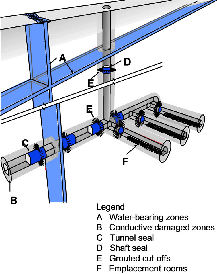
Figure 6. Schematic picture of low-order fracture zones in tunnel or drift isolated by bulkheads with grouted curtains [10].
holes is not really desired, the uppermost part of the holes, representing the blast-induced EDZ, is so conductive that sealing would be desired. This insight led to an attempt to seal the rock around deposition holes as part of the international Stripa Project [11]. Large packers with inflatable rubber rings at the ends were inserted in the 0.76 m diameter holes with about 3 m depth, and smectitic clay grout with a density of 1200 kg/m3 injected in the rock. The packers were used for determineing the hydraulic conductivity before and after the grouting, which was found to be reduced from 2E−9 - 9E−9 m/s for one hole and 3E−10 - 4E−7 m/s for a second hole, to less than E−9 m/s for the first mentioned and 3E−10 m/s for the other. The sealing effect was obvious but when the grouted holes were then heated to 100˚C for 3 months the conductivity had risen to the original value for the first hole and to about 1/3 of the original value for the second hole. The increased conductivity by heating may have been due to permanent coagulation of the soft clay grout or to erosion by thermally aided groundwater flow. The conclusion from the tests is that grouting of deposition holes can reduce the conductivity but not very significantly, and not permanently [6,11].
3.2.2. Blasted Tunnels and Shafts
Assessment of the water transport capacity of tunnels and shafts is primarily a matter of the conductivity and transmissivity of the EDZ. For visualizing their hydrological function of the structural components we will use a categorization scheme [2], according to which 1st order fracture zones have a persistence of more than E4 m and a very high average conductivity (>E−8 m/s), 2nd order zones with a persistence of E−3 - E−4 m and a medium/ high average conductivity (E−9 - E−8 m/s), and 3rd order zones persisting for E−2 - E−3 m and a medium/low average conductivity (E−9 - E−10 m/s). We will also refer to discrete water-bearing fractures as 4th order discontinueties with a persistence of E−0 - E−1 m, taking all other fractures to be of little mechanical and hydraulic importance in the present context.
Design and performance assessment of a repository requires access to a repository host rock model like the one in Figure 7.
One realizes that hydraulic characterization of the fracture zones is of fundamental importance for making large-scale flow analyses and predictions of the transport of escaped radionuclides. The basis of this is structural modeling, which is commonly made by using the simple concept of plane fracture zones of long extension and ascribing to them assumed bulk hydraulic properties [1]. A common spacing of major fracture zones representing 2nd order discontinuities is 100 - 1000 m, which makes it possible to fit in deposition tunnels and holes so that they will not interact with these weaknesses. Smaller zones of 3rd order with lengths of 100 to 1000 m and spacings of 10 to 100 m must not intersect canister positions but are allowed to cross the tunnels. The majority of these zones will not be known until repository construction has begun [1,6,9]. The accuracy of the predictions of flow is therefore low and the impact of exogenic processes like glaciations and tectonics make them largely invalid.
3.2.3. The Role of EDZ around Tunnels and Shafts
The deposition tunnels and shafts are surrounded by a continuous excavation-disturbed zone (EDZ) with a hydraulic conductivity that is at least 100 times higher than that of virgin rock [1,6,10]. It forms a continuous permeable zone that surrounds the tunnels and shafts and intersects major fracture zones through which radionuclides escaping from leaking containers can eventually reach the biosphere.
As indicated in Figure 6 two types of barriers in the rock have been proposed; bulkheads keyed into the rock for cutting off the EDZs, and grout curtains around them for hindering possibly contaminated groundwater to move in these zones. Both types work well theoretically but not in practice as we will see.
Figure 8 is a schematic plan view of part of an imaginary repository of presently favoured type in Sweden (SKB). The spacing of fracture zones of 3rd order (D3) in granite is typically 10 - 100 m, giving a rather low degree of utilization for placing canisters (50% - 70%). The figure illustrates the planned technique for minimizing groundwater flow through the backfilled tunnels by

Figure 7. Generalized model of the Forsmark HLW repository site. The green area is the ground surface and the blue plates 2nd order discontinuities with 100 m width. The red plates are 2nd and 3rd order discontinuities with 10 - 50 m width. Repository panels are marked black [2].

Figure 8. Plan view of part of a repository of Swedish type (KBS-3V) with deposition tunnels (DT) from the floor of which holes for canisters extend to about 8 m depth (DH). MT is main tunnel. Tight plugs (P) are keyed into the rock for cutting off the EDZ (5). Fracture zones (3) are assumed to form a regular pattern. The rock matrix contains systems of more or less continuous, discrete water-bearing fractures (4) [2,6].
constructing bulkheads keyed into the rock.
3.3. Sealing of Fracture Zones and EDZ around Tunnels and Shafts
3.3.1. What Is the Basis for Performing Hydrological Analyses of Host Rock?
In practice, structural modeling of the host rock is made on a very weak basis as illustrated by the fact that solid information on the system of significantly important structural features is obtained by examination of borehole cores and measurements in a very small number of cored boreholes representing about 1/10,000,000 of the total volume of the repository host rock. This is realized by planners and designers who try to apply advanced statistics for making the models trustworthy [12], but there is no way of validating them, not even if the rock has been richly instrumented for cross-hole physical and hydraulic measurements, which is strongly opposed because cables to sensors and cells will serve as shortcircuits for transport of water and radionuclides [2].
3.3.2. Bulkheads
Bulkheads for sealing tunnels will be made of concrete and for providing best possible sealing effect they shall be located where the rock is poor in fractures and so that fracture zones become hydraulically isolated. The bulkheads need to be strong enough to resist the water pressure, which can give a force of several thousand tons (hundreds of MN) in the construction phase at 400 m depth. This requires use of concrete with a content of Portland cement of 15 - 25 percent by weight and superplasticizers but no reinforcement since iron will produce hydrogen gas in a long time perspective and iron compounds that can reduce or eliminate the swelling capacity of clayey tunnel backfill. The superplasticizers planned to be used are organic and give off organic colloids that can carry radionuclides from leaking canisters and they have recently been banned.
The bulkheads have to be keyed into the rock for cutting off the EDZ as indicated in Figure 8 but the problem is that new EDZs are formed around their edges and combine with the stress-generated EDZ along the entire tunnel to give significant flow in the rock along the tunnels and shafts. The systems of tunnels and drifts in a blasted repository hence represent preferential flow paths of water carrying radionuclides having escaped from canister deposition holes. The conditions get worse with time since the chemical stability of concrete with Portland cement is estimated to be only about a hundred years [7,13]. Bulkheads can therefore not be relied on as barriers to migration of contaminated water for more than a very small fraction of the requested time for isolation of the nuclear waste, which is up to 100,000 years.
3.3.3. Grouting
Grouting of the rock around bulkheads or of fracture zones is planned to be made by injection of cementitious slurries in systems of regularly spaced boreholes, i.e. “curtains” (Figure 3). The degree of success of injecting grout depends primarily on the probability of hitting groutable fractures and the experience is that the spacing of the holes should not exceed 0.5 to 1 m [1,14].
Proper evaluation of performed grouting requires use of ventilation techniques before and after the grouting campaign implying circulation of the air in a confined, heated part of the drift in question, with continuous determination of the humidity until steady state conditions are reached (Figure 9). The inflow of water can then be calculated and the efficiency of the grouting evaluated [15]. This principle is scientifically and technically sound and can be relied on. It has given relevant information on the effect of grouting of fracture zones as exemplified here.
Pre-grouting of rock where a drift or tunnel is about to be blasted is commonly considered to be more effective than grouting after construction since movements of rock blocks induced by the blasting and creation of new fractures will distort the grout and raise the conductivity. The largely unknown hydraulic performance of the virgin rock makes even very systematic grouting a hazard and postgrouting will usually be required. Comprehensive field tests in the Swedish Stripa mine using systematic postgrouting of cementitious materials have shown that the average hydraulic conductivity of typical fracture zones of 3rd order in granite cannot be reduced to less than about E−9 m/s from an initial value of E−8 m/s [8,10]. The effect was hence small, partly because of the too large borehole spacing (0.7 m) and partly because of the fact that tightening of rock raises the water pressure and increases the hydraulic gradient, causing piping and erosion [8]. Evaluation of the effect of grouting is sometimes made by pressurizing individual grout holes after re-boring and comparing the inflow before and after the grouting, but this only gives a measure of the sealing


Figure 9. Principle of determining the effect of grouting by ventilation testing. Upper: Inflow from intersected fracture zone. Lower: Expected redirection of groundwater flow around the grouted zone.
effect of the nearest vicinity of the holes. Measurements in new holes bored among grouted holes are of no value since the rock around them will be located in differently structured rock.
Postgrouting, based on rock structure models, means that grout is injected in a limited number of boreholes oriented so that they intersect identified water-bearing fractures of 4th order [16-18]. This can have a good temporary effect but requires that the rock to be grouted is supported so that new fractures will not be formed. An example of this principle is a field experiment of grouting the surrounding of a bulkhead at about 350 m depth in granite [6,10]. The grout was Li-saturated smectite clay with a density of 1200 kg/m3 injected in 5 subhorizontally oriented 56 mm cored boreholes by “dynamic injection” using oscillating pumping with peak pressures up to 4 MPa [14,19] (Figure 10). The bulkhead separated an inner part of a drift filled with water that was pressurized up to 3 MPa, generating hydraulic gradients over the 3 - 5 m long grout holes of up to 100 m/m.
The outflow from the drift was reduced from about 20 l/h to 12 l/h for a water pressure of 1 MPa, but raising the pressure beyond this level caused extrusion of grout from one of the sealed fractures.
The overall conclusion from this experiment was that the technique and grout material worked well but that the net effect of grouting was not satisfactory since the EDZ,

Figure 10. Top view of field experiment showing 5 discrete fractures injected with clay grout through 5 strategically oriented boreholes (IVIII). C is the concrete bulkhead, HCB an “O-ring” of highly compacted blocks of smectite clay, and S the water-saturated sand-fill in the drift that was pressurized for testing the tightness of the grouts in the fractures.
rich in fine fractures around the tight bulkhead, was an effective conductor that controlled the outflow.
The possibility of sealing the EDZ around blasted tunnels by grouting has been investigated by conducting a large-scale field experiment involving a large number of about 0.9 m deep grout holes with a spacing of 0.7 m over the entire 75 m2 large wall of a blasted tunnel in granite (“Hedgehog boring”). The “dynamic injection technique” was used and the evaluation showed that the average hydraulic conductivity E−9 m/s was not reduced to more than 5E−10 m/s, hence demonstrating the limited sealing effect of post-grouting [8,10].
The sensitivity of both clay-based and cementitious grouts to erosion and dissolution makes their sealing capacity low and, like the bulkhead concrete, their sealing effect cannot be counted on for more than one hundred years because of chemically generated degradation [10,13].
A general conclusion from all these attempts to seal or isolate fracture zones for minimizing their role as conductors by constructing bulkheads and grout curtains is that they have only a very small and temporary effect. Crystalline host rock of repositories will hence perform as if the rock were unsealed already a hundred years after closure.
4. THE SPECIAL CASE of BOREHOLE SEALING
4.1. Role of Boreholes
Like shafts extending from the ground surface to the repository level deep boreholes can bring radionuclides to the biosphere by flowing water driven by pressure differences, or by diffusion unless they are effectively sealed. The boreholes short-circuit the system of fracture zones, and need to be sealed since they can otherwise cause contamination of the zones and also bring radionuclides directly up to the ground surface. They may in fact represent more critical pathways than the system of tunnels and shafts if they intersect fracture zones on the repository level in the central part of the repository (Figure 11).
4.2. Sealing of Boreholes
The basic principle worked out for borehole sealing is the same as for repository tunnels and shafts, i.e. to tightly seal those parts where the rock has few fractures and a low hydraulic conductivity with clay, and fill the parts that intersect permeable fracture zones with physically stable material—concrete—that does not need to be very tight but mechanically strong for supporting the clay segments. Shear displacements in the rock generated by seismic shocks and tectonic strain will primarily take

Figure 11. Schematic view of repository rock with a repository located between major fracture zones of 2nd order (I, II, III) and with boreholes intersecting the repository and fracture zones [16].
place along fracture zones and degrade borehole seals located in them. Here, clay would be dispersed and lost while concrete with a low content of cement remains on site and maintains its sealing effect that is mainly mechanical [16].
The clay seals consist of highly compacted smectite clay (“bentonite”) fitted in perforated copper tubes (Figure 12) placed on concrete seals cast where fracture zones are intersected. Clay swells out through the perforation and forms a tight skin between the tubes and the rock and completely closes and seals off the borehole. The technique has been tested and applied in several large-scale projects [2,6,16].
In contrast to blasted tunnels cored holes have only a small EDZ and practically no flow will take place in the holes along the clay/rock contact. Since recently developed concretes are less conductive than the intersected fracture zone groundwater will simply flow around the borehole [16,20].
Technically, the procedure is rather advanced since the holes must firstly be stabilized so that the clay segments can be placed and casting of the concrete be made without risk of failure caused by falling debris from the borehole walls (Figure 13), and, secondly, be sealed at a rate that allows the concrete to stiffen sufficiently much to carry the up to 24 m long jointed tubes with clay placed on it. The concrete must be poor in cement for minimizing the risk of creation of voids caused by dissolution of the cement and it should have silica-rich aggregate and inorganic superplasticizer. Enough wall fric-

Figure 12. Perforated copper tube with highly compacted smectite clay. Tubes are jointed to form long segments that are inserted in the holes (Drawing by Sweco Int. Co).
tion is produced in about 1 day by the expanded clay to make each clay segment carry itself [20,21]. A suitable cement content is about 7 weight percent and density about 2200 kg/m3 [9,20] and a low pH-cement is suitable since it has minimum chemical impact on the clay in adjacent seals. A schematic borehole profile is seen in Figure 14, showing the calculated compressive strength of the concrete seals and the vertical pressure on them.
The curves in Figure 14 were derived from calcula-

Figure 13. Technique for stabilizing boreholes. Left: Borehole intersecting fracture zone; Center: Reamed hole filled with concrete between packers; Right: Reboring giving a stabilized hole [22].


Figure 14. Example of deep borehole with concrete seals where the hole intersects fracture zones, and clay seals where the rock is tight. Upper: Generalized borehole profile. Lower: Compressive strength (upper curves for each stage) and vertical effective stress in MPa (lower curves).
tion of the effective pressure (total pressure minus pore water pressure) at each stage, hence representing the contact pressure between a previously installed seal and the next one, the requirement being that the effective pressure of the latter must be lower than the bearing capacity of the first mentioned. For Stage 1, representing the lowest concrete seal, the effective compressive pressure on the bottom of the hole is about 1.4 MPa, while for Stage 2, after placing the lowest clay seal, the effective pressure on the bottom is about 2 MPa and the pressure on the concrete (p6) about the same. For Stage 3, i.e. when the second concrete seal had been cast, the pressure at the bottom has increased to 3.2 MPa and to about the same value at the contact between the first concrete seal and first clay seal. This is due to the fact that the clay adheres to the rock and carries itself. For Stage 4, when the second clay seal has been inserted the pressure at the bottom has increased to 5.2 MPa and to about 5 MPa at the contact between the first concrete seal and first clay seal. For Stage 5, when the third concrete seal has been cast over the second clay seal the pressure at the bottom has increased to about 5.5 MPa, to roughly the same value at the contact between the first concrete seal and first clay seal, and to about 2.5 MPa at the contact between the second concrete and second clay seal. At each of these stages and at the subsequent sealing the calculated bearing capacity is higher than the effective pressure. For the latest stage the maximum effective pressure is nearly 8 MPa deeper than about 800 m, which is lower than the compressive strength of the concrete but somewhat higher than the swelling pressure of the clay. Since the clay seals are confined in the perforated copper tubes they will, however, not be compressed.
4.3. Performance of Sealed Boreholes
The clay seals confined in the perforated tubes behave as stiff units in the holes, each of them resting on concrete cast a couple of days earlier. The compressive strength of the concrete increases with time and even if the cement component, which is far more stable than Portland cement, will ultimately be dissolved, the dense aggregate of the degraded concrete, having the same bearing capacity as moraine, remains coherent and continues to carry the clay seals. These adhere to the rock and maintain their low hydraulic conductivity, E−12 to E−11 m/s for hundreds of thousands of years because of the high chemical stability under the prevailing temperature conditions (<50˚C), [1,23]. By using Portland cement in the concrete seals pH would be high (13) for a limited period of time and cause dissolution of parts of the adjacent clay seals [21] but the new types with very little low-pH cement and talc as superplasticizer are long-lived and affect the contacting clay much less and therefore keep the sealed boreholes tight for the required period of time.
5. DISCUSSION AND CONCLUSIONS
Application of the multibarrier concept implies that the tightness of the host rock is counted on. The problem is that temperature effects will cause internal movements in the host rock, activating water-bearing fractures and creating new ones, and that future exogenic impact in the form of glaciations, seismic and tectonic events impacts will alter the entire spectrum of rock discontinuities [9]. This has long been realized by designers and a number of attempts have been made for improving the tightness of the host rock. As concluded from the examination of the presently available ways of doing so, i.e. construction of bulkheads and grout curtains, none of them will be effective after a hundred years.
For concepts implying excavation of tunnels and shafts by blasting, assessment of the role of the excavation disturbance—EDZ—on the percolation of a repository shows it to be dominant, and that bulkheads in combination with grouting do not provide the host rock a potential to isolate highly radioactive waste effectively. Only totally and permanently tight canisters can be relied on and very corrosion-resistant and ductile types like the 100% copper HIPOW type have to be considered as pointed out by Pusch et al. [9,24]. The host rock of a deep geological repository with blasted deposition tunnels merely serves as a mechanical protection of the “chemical apparatus”.
Boreholes, on the other hand, can be sealed effectively for very long periods of time since they have almost no EDZ and also because new types of clay and concrete seals have become available. This also suggests that concepts of the type “very deep bored holes” for disposal of HLW canisters should be reconsidered [4,25].
REFERENCES
- Svemar, C. (2005) Cluster Repository Project (CROP). Final Report of European Commission Contract FIR1-CT-2000- 2003, Brussels.
- Pusch, R. (2008) Geological storage of radioactive waste. Springer-Verlag, Berlin and Heidelberg. doi:10.1007/978-3-540-77333-7
- Liu, X.D., Prikryl, R. and Pusch, R. (2011) THMC-testing of three expandable clays of potential use in HLW repositories. Applied Clay Science, 52, 419-427. doi:10.1016/j.clay.2011.03.021
- Marsic, N., Grundfeldt, B. and Wiborgh, M. (2006) Very deep hole concept. SKB Report R-06-59. SKB, Stockholm.
- Liedtke, L., Shao, H., Alheid, H.J. and Sönnke, J. (1999) Matrial transport in fractured rock-rock characterization in the proximal tunnel zone. Technical Report, Federal Institute for Geosciences and Natural Resources, Hannover.
- Pusch, R. (1994) Waste disposal in rock. Elesevier Publica- tions Co., Amsterdams.
- Pusch, R. and Weston, R. (2012) Superior techniques for disposal of highly radioactive waste (HLW). Nuclear Energy, 59, 75-85. doi:10.1016/j.pnucene.2012.01.005
- Börgesson, L., Pusch, R., Fredriksson, A., Hökmark, H., Karnland, O. and Sandén, T. (1992) Final report of the Rock Sealing Project—Sealing of zones disturbed by blasting and stress release. Stripa Project Technical Report TR 92-21, Swedish Nuclear Fuel and Waste Handling Company (SKB), Stockholm.
- Pusch, R. (2012) The geological basis for developing concepts for disposal of highly radioactive waste (HLW) in crystalline rock—A state of art compilation. Comunicações Geológicas, 99, 61-68.
- Gray, M.N. (1993) OECD/NEA International stripa project, overview volume 3, engineered barriers. Swedish Nuclear Fuel and Waste Management Co. (SKB), Stockholm.
- Börgesson, L., Pusch, R., Fredriksson, A., Hökmark, H., Karnland, O. and Sandén, T. (1991) Final report of the rock sealing project—Sealing of the near-field rock around deposition holes by use of bentonite grouts. Stripa Project Technical Report TR 91-34, Swedish Nuclear Fuel and Waste Handling Company (SKB), Stockholm.
- Bosson, E., Sassner, M., Sabel, U. and Gustafsson, L.-G. (2010) Modelling of present and future hydrology and solute transport at Forsmark. SKB Report R-10-02, Swedish Nuclear Fuel and Waste Management AB (SKB), Stockholm.
- Alcorn, S.R., Coons, W.E., Christian-Frear, T.L. and Wallace, M.G. (1991) Theoretical investigation of grout seal longevity. SKB Technical Report TR 91-24OECD/NEA International Stripa Project, SKB, Stockholm.
- Pusch, R., Börgesson, L., Karnland, O. and Hökmark, H. (1991) Final report on test 4—Sealing of natural finefracture zone. Stripa Project, Technical Report TR 91-26, SKB, Stockholm.
- Witherspoon, P.A., Cook, N.G.W. and Gale, J.E. (1985) Progress with field investigation of Stripa. University of California, San Francisco.
- Pusch, R. and Ramqvist, G. (2007) Borehole projects— Final report phase 3. SKB R-07-58, SvenskKärnbränslehantering AB (SKB), Stockholm.
- Emmelin, A., Brantberger, M., Eriksson, M., Gustafson, G. and Stille, H. (2007) Rock grouting. Current competence and development for the final repository. SKB R-07-30, SvenskKärnbränslehantering AB (SKB), Stockholm.
- Fransson, Å. (2008) Grouting design based on characterization of the fractured rock—Presentation and demonstration of a methodology. SKB R-08-127, SvenskKärnbränslehantering AB (SKB), Stockholm.
- Pusch, R., Erlström, M. and Börgesson, L. (1985) Sealing of rock fractures. A survey of potentially useful methods and substances. SKB Technical Report TR 85-17. Swedish Nuclear Fuel and Waste Management AB (SKB), Stockholm.
- Pusch, R., Warr, L., Grathoff, G., Pourbakhtiar, A., Knutsson, S. and Mohammed, M.H. (2012) A talc-based cementpoor concrete for sealing boreholes in rock. In preparation.
- Warr, L. and Grathoff, G. (2010) Sealing of investigation boreholes: Mineralogical and geochemical borehole plug analyses. SKB Technical Report (in print). Ernst-MoritzArndt-Universität Greifswald, Greifswald.
- Tauno, R. and Suomen Malmi, O. (2006) Borehole plugging experiment in OL-KR24 at Olkiluoto. Posiva Working Report, Posiva.
- Pusch, R. and Yong, R. (2006) Microstructure of smectite clays and engineerimg performance. Taylor & Francis, London and New York.
- Pusch, R., Knutsson, S., Al-Taie, L. and Mohammed, M.H. (2012) Optimal ways of disposal of highly radioactive waste. Journal of Natural Sciences, In print.
- Pusch, R. and Börgesson, L. (1992) PASS—Project on alternative systems study. Performance assessment of bentonite clay barrier in three repository concepts: VDH, KBS-3 and VLH. SKB Technical Report TR-92-40, SKB, Stockholm.