Design Procedure and Simulation of a Novel Multi-Modal Tactile Display Device for Biomedical Applications ()
1. Introduction
This tactile display of real objects in virtual environments has recently attracted much interest in the field of virtual reality [1] . A tactile display device is a Human Computer Interface that can reproduce, as closely as possible, the tactile parameters of an object, such as shape, softness, surface texture, roughness, vibration and temperature [2] . For humans, tactile sensations are perceived through mechano-receptive units embedded in the outer layers of the skin, which in turn transmit signals to the brain when stimulated. Tactile displays can serve as an alternative for information transmission through the stimulation of the human skin to induce tactile perception [3] [4] .
A device which can display shape and convey the feeling of soft tissue hardness is needed for several applications and one very important application is laparoscopic surgeries. The surgeon find himself only with an image of patient interior from which he can only infer the tissue shape but unable to feel the hardness as compared to the open surgeries. Therefore it would be quite useful if we can provide him with a device which can display the stiffness in such case.
The literature of tactile display devices is huge and diverse. Several basic physical concepts were used to develop the tactile display devices including electromagnetic, piezoelectric, controlled viscosity fluids, conjugated polymers and Shape Memory Alloy, SMA, techniques [2] . Tactile display devices based on electromagnetic fields are affordable and easy to be controlled and provide the highest forces up to 1.7 N [5] [6] . These kinds of devices however can be bulky and suffer from interference from other devices using electromagnetic fields which are common. Tactile display systems based on piezoelectricity give low displacements with high bandwidth but they require high voltage which may not be feasible in particular for medical applications [7] . Depending on this property, research was done in (Stimulator for Tactile Receptors by Skin Stretch) STRess [8] using bimorphs to stretch the skin laterally. It could deliver 25 micrometer but it was recently reported to be more robust and reached 0.1 mm deflection with bandwidth in the range 0 - 1 kHz [9] .
Some controlled viscosity fluids could be used in tactile display systems such as the MRF, ERF, for which the viscosity of the fluid can be controlled through magnetic or electric field respectively. High voltage is also required for this application (maximum 10 kV per 20 mA) and a fabric is needed between the layers to prevent short circuit and to increase the force [10] . The conjugated polymers are consisting primarily of an electrolyte between conductive polymers which have a powerful actuation with up to 15% strain and 49 MPa and a stretchable actuator with 34% strain and up to 10 MPa, but not yet tried [11] [12] .
Shape Memory Alloy was used as an actuator for tactile display systems, because of its high power to volume, power to weight and force to weight ratios. SMA tactile display device can achieve, as large array as 16 × 16 [13] , as high spatial resolution as 1.27 mm [14] , as long range of motion as 120 mm [1] , response time of 0.4 seconds [15] , and as light weight as 60 g [16] .
The current devices are displaying only one of the following properties:
1) Display the shape of an object.
2) Display mechanical vibration for tactile feedback.
3) Display the softness of an object (very limited trial using Electro Rheological Fluids-ERF and Magneto Rheological Fluids-MRF).
Basically, the objective is to develop a device which can display two properties (both shape and stiffness of soft tissue). Therefore, it is suggested that multi springs can be utilized to realize this task. If the elongation and stiffness of the springs can be controlled then, we can change both the shape and stiffness of the combined mechanical system. In this paper, the conceptual design of a multimodal tactile display device will be introduced. The device will consist of several pins; each one is made of two springs, Elongation Spring (ES) and Stiffness Spring (SS) for displaying shape and stiffness, respectively. The spring material is selected as SMA in order to control its elongation and stiffness simultaneously. The spring parameters are selected to display the stiffness of human/animal organs (soft tissue). The selected springs constants are then simulated to explore how the elongation spring can affect the overall stiffness of the pin.
This paper is organized as follows; the next section presents the basic concept of operation of the new device. Section 3 describes the design considerations and design procedure. The method of Finite Element Analysis (FEA) is applied to validate the concept design in Section 4. Conclusions are then given in Section 5.
2. Conceptual Design of the Multi-Modal Tactile Display Device
The tele-transmission of the tactile perception, as shown in Figure 1, is consisting of tactile sensor for acquiring the tactile data such as shape and stiffness, signal processing unit, and tactile display device for displaying the tactile data.

Figure 1. The tactile perception system.
In this work, in order to display shape and stiffness, a matrix of a 5 × 5 pin units, with a spatial resolution of 5 mm is arranged as shown in Figure 2.
The shape of an object is represented by the elongation of the pins array. So the shape of a liver (Figure 2(a)) can be displayed by the pins array in Figure 2(b). The difference between the stiffness of liver tissue (soft) and abscess tissue (hard) can be represented by changing the middle pins stiffness (shown in dark color to present feeling of hard object in the middle of the liver).
To realize this, each display pin unit uses two decoupled SMA springs; one of them (ES) is responsible for displaying the object shape/height through changing its elongation. The second spring (SS) is responsible for displaying stiffness. This stiffness information can be transmitted only when the user presses the display pin. These springs are located on series one above the other, as shown in Figure 3.
So the user can feel the resultant change of both shape/height and stiffness of an object simultaneously.
The lower spring (ES) is squared and ground compression spring, depending on the Two Way Shape Memory Effect (TWSME). It is trained to remember two different shapes; the contracted shape in Martensitic phase and the elongated shape in Austenitic phase so that it is responsible for displaying the shape/height. The TWSME is selected here as it can elongate to display shape when heated and it will return to its original shape when cooled with no need for external bias spring for driving it back. This spring is settled on the medial plate and wound around a collar that can move freely upwards and downwards inside a guide in the medial plate, as shown in Figure 3.
The upper spring (SS) is squared and ground compression spring depending on the One Ways Shape Memory Effect (OWSME) that is trained to stiffen/soften while keeping its original shape so that it is responsible for displaying only the stiffness.
This spring is settled on the collar and wound around another pin of diameter 2 mm that can move freely upwards and downwards through the collar.
The collar can then be moved upwards and downwards by applying electrical current to elongation spring ES that will push the group of SS and the pin upwards and downwards within a stroke of 10 mm. On the other hand, stiffness spring (SS) can be actuated by applying electrical current to control its stiffness. In this way, the tactile display system can be configured to present the tactile information.
The tactile display unit can be modeled as two springs in series, as shown in Figure 4. The resultant stiffness, kR, can be computed from the well-known equation of two springs in series:
 (1)
(1)
where kst and kEl are the stiffness constants of the stiffness and elongation springs, respectively. Subsequently, the stiffness spring (SS) will be the dominant spring stiffness of the whole system.
In the next section, we show how to evaluate the spring stiffness to satisfy these conditions. kst and kEl can be chosen so that the resultant stiffness kR is made equal to kst only.
3. Design Considerations
In this section, the springs’ stiffness constant of the device will be selected in order to present the stiffness of

Figure 2. Tactile display of liver with abscess, (a) liver with abscess, (b) tactile display of the liver shape and the abscess hardness.

Figure 3. Schematic of the structure of Multimodal tactile display device.
soft tissue. The first step in this process is to find the stiffness range of the soft tissue of some human and animal organs, as described in the next subsection.
3.1. Stiffness Display Range
The stiffness display values depend on both, the display pin dimension and the geometry of the tissue being displayed. This concept is slightly different from the concept of the young’s modulus of a material which is unique and fixed value for each material. Hayes et al. [17] presented a mathematical model for the elasticity problem of indentation test as follows:

Figure 4. Tactile display pin and its lumped parameters.
 (2)
(2)
where, F, w, a, ν and h are the applied force (here this force will be applied by a finger), indentation depth (tissue deflection), radius of the display pin, Poisson’s ratio of the tissue and the tissue thickness, respectively, as shown in Figure 5.
However, Ck is a scaling factor depends on ν, (a/h) and (w/h). By modifying (2), the stiffness of the soft tissue, which will be presented by the tactile display device; (kst = F/w) can be expressed as:
 (3)
(3)
Poisson’s ratio can be assumed to be 0.3 as a mean value. Equation (3) can be used for determining the stiffness range based on the expected range of Young’s modulus and the scaling factor Ck. Young’s modulus of 100 kPa is selected as the display upper range based on the previously reported values by several researchers. For instance, Chinzei et al. [18] showed experimentally that the Young’s modulus of swine brain is about 7.425 kPa. Farshad et al. [19] performed a series of aspiration experiments using a pig’s kidney; the results showed that the Young’s modulus of the pig’s kidney was 43.5 kPa. Kim et al. [20] developed a system for measuring the mechanical properties of soft tissue of a pig in vivo. The results showed that the Young’s modulus were 31.8 and 48.8 kPa for the liver and the esophagus, respectively. Zheng and Mak [21] , studied the biomechanical properties of human lower limb soft tissues and reported that the Young’s modulus ranges from 10.4 to 89.2 kPa.
In order to estimate the stiffness display range, it is required to select the display pin diameter and the tissue height. It is assumed that, the tissue height from a bony layer to the outer skin layer should be less than 10 mm. The display pin diameter is selected as 2 mm to suit the spatial resolution of human fingertip (ranging from 1.5 to 3 mm [22] ).
Zhang et al. [23] estimated the value of Ck and reported it to be 1.15 assuming ν = 0.3, a/h = 0.1, w/h = 50% through a non linear FEA.
Using the values of pin diameter 2 mm (a = 1 mm), ν = 0.3 and Ck = 1.15, the maximum kst can be obtained
250 N/m at E = 100 kPa. However, the value of the stiffness display range can be changed according to the application.
3.2. Spring Stiffness Selection
The spring stiffness kst and kEl will be selected to display stiffness of 250 N/m as upper limit and one third of this value; i.e. 85 N/m as lower limit. The selection of this ratio is based on the available change ratio in the Young’s modulus between the Martensite (E = 28 GPa) and Austenite (E = 80 GPa) phases of SMA. According to this ratio, the design will represent soft tissue elasticity ranged from 35 to 100 kPa, as calculated from Equation (3). Table 1 summarizes the mechanical properties of NiTi as a SMA material [24] .
For displaying stiffness ranged from 85 to 250 N/m the stiffness spring will be designed to give 85 N/m at Martensite phase. And according to Equation (1), kEl should be selected so that the total stiffness kR equals kst. For this purpose, assuming that kEl = N × kst, this will result in kR = m × kst, where m is the agreement factor. For ideal case the agreement factor (m) should be equal 1 to get kR = kst. By increasing N, the total stiffness becomes almost equal to kst, as shown in Figure 6. At N = 10, kR = 0.9 kst. For this reason kEl is selected to be equal to 10 × kst N/m.
3.3. Selection of Spring Dimensions
The dimensions of ES and SS will be selected to achieve the above stiffness values. Spring stiffness, k can be calculated by the following equation [25] :
 (4)
(4)
where: G is the spring modulus of rigidity, Dw, Dm and Na are spring wire diameter, spring mean diameter, and number of effective coils respectively, as shown in Figure 7.
The selection of Dw should be as small as possible to keep small values of the applied current to actuate SMA springs because the applied current to SMA increases with the increase in Dw so, the dimension of elongation spring; ES, and stiffness spring; SS, could be determined using Equation (4) while keeping the spring index; C = Dm/Dw, within the allowed range of 5 ≤ C ≤ 12 [25] . Table 2 shows the spring dimensions and modulus of rigidity in the Martensite and Austenite phases to achieve the desired stiffness/display range.
The parameters shown in Table 2 are selected based on 10 mm displacement range. For increasing this range the number of turns; Na, should be increased and subsequently the Dw, and Dm, should be increased for keeping the same spring stiffness. This will increase the device size and subsequently its spatial resolution will be lowered. The designed spring parameters will be evaluated to decide its ability to display the desired stiffness and shape ranges as in the next section.
4. Simulation of a Pin Unit by Finite Element Analysis
A finite element model was applied to simulate the resultant stiffness (kR) that will be displayed by the tactile
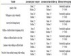
Table 1. Mechanical properties of NiTi.

Figure 6. Selection of the ratio between (kEl/kst).

Figure 7. Schematic drawing of the spring parameters.
display device. The material of springs ES and SS are assumed to be linearly elastic with Poisson’s ratio of 0.33. Solid tetrahedral elements are used for meshing the model, as shown in Figure 8. Large deformation was taken into consideration in the analysis by choosing nonlinear geometry and applying the load incrementally. The load is applied as a pressure on the pin top surface to cause a force increasing from 0 to 1 N.
Four simulation cases are studied to represent the resultant stiffness of the device in the case of displaying the softest and hardest stiffness when ES are at minimum (0 mm) and maximum elongation (10 mm). Figure 9 shows the four simulation cases. The corresponding resultant stiffness is presented in Figure 10 as follows;
The dashed line in Figure 10 represents the system behavior while the Young’s modulus of SS = 28 GPa, to represent the softest case in Martensite phase and Young’s modulus of ES = 40 GPa, to represent the elonga-

Figure 8. Finite Element Model for stress analysis.

Figure 9. The tactile display pin simulation behavior; (a) ES and SS not actuated (contracted & soft), (b) ES not actuated (contracted), SS actuated (hard), (c) ES actuated (elongated), SS not actuated (soft), (d) ES actuated (elongated), SS actuated (hard).
tion spring in the compressed situation (zero elongation), in Martensite phase, as shown in Figure 9(a). This gives resultant stiffness = 95 N/m.
The solid line in Figure 10 represents the system behavior while the Young’s modulus of SS = 80 GPa, to represent the Austenite phase, i.e. the hardest case, and Young’s modulus of ES = 40 GPa, to represent the

Figure 10. Force-displacement relationship of the total system and its equivalent stiffness.
elongation spring in the compressed situation (zero elongation), i.e. Martensite phase, as shown in Figure 9(b). This gives resultant stiffness = 275 N/m.
Young’s modulus of SS = 28 GPa, to represent the softest case in Martensite phase and Young’s modulus of ES = 80 GPa, to represent the maximal elongation (Austenite phase), as shown in Figure 9(c) and it resulted in resultant stiffness almost the same as that of the dashed line in Figure 10 (resultant stiffness = 95 N/m).
The Young’s modulus of SS = 80 GPa, to represent the hardest case in Austenite phase and Young’s modulus of ES = 80 GPa, to represent the elongation spring in the maximal elongated situation, i.e. Austenite phase, as shown in Figure 9(d) and it resulted in resultant stiffness almost the same as that of the solid line in Figure 10 (resultant stiffness = 275 N/m).
Figure 11 shows that the total stiffness of the system can be set to as lower stiffness as 95 N/m, when SS is controlled to be in Martensite phases. This stiffness is independent of the applied displacement of the display pin and the elongation of the elongating spring (ES, which is used for displaying the shape). Also, the total stiffness of the system can be set to as higher stiffness as 275 N/m, when SS is controlled to be in Austenite phase (the control hardware and strategy are out of this paper’s scope). The simulation shows that total stiffness kR is not depending on the applied force/displacement, which applied by the finger during indentation for feeling stiffness. Moreover, it is independent of the stiffness of ES during actuation since the error in the total stiffness does not exceed 1.2%.
5. Conclusions
The conceptual design of a multimodal tactile display device for displaying both the shape and stiffness of an object was presented. The tactile display device consists of two springs, one for displaying the shape and the other for stiffness display. The spring material is made of SMA to control its shape and stiffness. The spring parameters are selected to display the stiffness of human/animal organs (soft tissue). In the design process, it was shown that by using a display pin of 2 mm diameter and tissue Young’s modulus ranging from 35 to 100 kPa (which is associated with the soft tissue property), the soft tissue can be displayed by spring stiffness of 85 to 250 N/m, respectively.
The designed spring’s parameters are simulated for the purpose of the design validation. The simulation showed that the proposed device can display stiffness ranging from 95 to 275 N/m, independent of shape displacement/display with total stiffness error less than 1.2% during the finger indentation for feeling stiffness. In the future, the device will be implemented and integrated with a control system to maintain the SMA behavior within the designed range of stiffness and elongation.

Figure 11. Stiffness-Displacement relationship of the total system.
Acknowledgements
The first author is supported by a scholarship from Mitsubishi International Corporation which is gratefully acknowledged.