1. Introduction
The interest in the transient analysis of electromagnetic phenomena has been growing in recent year. This is due to the advance of Ultra-Wide Band (UWB) radars and their associated antennas, various antennas have been proposed for UWB application [1], with mobile radio channels by means of their response to pulsed excitation [2]. It is more efficient do deal with the transient analysis directly in the time domain.
There exist several analytic and numerical techniques for obtaining the response of scattering problems directly in the time domain, which is the most natural approach to be used, such as the finite-difference time-domain method (FDTD) [3], the time-domain uniform theory of diffraction (TD-UTD) [4], and the space-time integral-equations become intractable when the incident pulse width is extremely narrow with respect to the dimensions of the scattering object. These techniques have inherent difficulties with numerical instability, interpolation errors, and need of extensive computer memory and CPU time to solve problems involving large scatterers. This fact makes the use of asymptotic methods such as time domain physical-optics (TDPO) [5,6]. This method requires relatively small amounts of computer memory and CPU time.
For large scatterers, the physical-optics approximation is an efficient method in the frequency domain [7,8]. This physical-optics (PO) approximation is initially applied in the frequency-domain with the inverse Fourier transform [9,10].
In this paper, we use the time domain physical-optics (TDPO) approximation, for the analysis of a rectangular reflector illuminated by a Gaussian-impulse considering the UWB radar application. In addition, we focus on some numerical results to verify the validity and applicability of TDPO.
2. Formulation of the Problem
The scattered field of the TDPO is obtained as follows:
 (1)
(1)
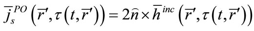
where  is given as:
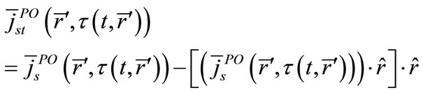 (2)
(2)
 . (3)
. (3)
where the vector  locates the integration point on the scatterer surface, r is the distant observing point, c is the velocity of the light and is
  the intrinsic free space impedance,

is the surface-current distribution in the time domain and  is the time-domain magnetic field incident on the surface. The delay time of the propagation is given by:
 , (4)
, (4)
3. Response of a Rectangular Reflector Antenna to a Gaussian-Pulse
Figure 1 shows the geometry of a Rectangular reflector illuminated by an incident wave. We assume that incident wave is bandpass Gaussian-pulse transmit from x-polarized small dipole point source which has the following form:
 , (5)
, (5)
 is the standard deviation of Gaussian envelope, B is the magnitude parameter of impulse, and
  is the center frequency.
From Equation (5) we can form the time – domain representation v(t):
 , (6)
, (6)
as a real signal, we can write v(t) as:
 (7)
(7)
where F(t) is analytic low pass input signal,
 where
where
 and
and
 where I and Q are the In-phase and quadrate parts. F(t) corresponds to the complex envelope of v(t) and useful to know the intensity of the scattered wave in time domain.
Our next step in being able to show how such a bandpass system can be given an equivalent baseband representation at the center frequency, as
 . (8)
. (8)
The baseband output is the sum over each path, of the delayed replicas the baseband input. When we get the U (t), it is possible to draw dB plot, as shown in Figure 4.
4. Numerical Results
Numerical results were obtained for a variety of configurations. As a target, we use a PEC rectangular plate as shown in Figure 1, where  is the wave length and
 .
.
Figures 2(a)-(c) show the early time response of the monostatic scattering. From Fermat’s principle, three scattering components shall be distinct, i.e. specular reflection at the center of rectangle, edge diffraction at the center of the edge, and corner diffraction at the corners shown in Figures 2(a)-(c), respectively. In Figures 2(a)-(c), the reflectors diameter are 1cs, 3cs, and 6cs, respectively. TDPO results appear to be more accurate and stable faster than those obtained by frequency domain physical optics.
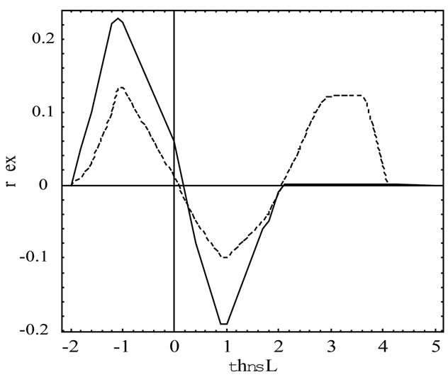
Figure 3 shows the response of the rectangular for the observation point near a shadow boundary of the reflector with coordinates r = 100 m,  , calculated using the TDPO. The dB plot is drawing, as shown in Figure 4.
5. Conclusion
We extended the concept of the frequency-domain physical optics approximation to time-domain to determine the analysis of a rectangular reflector illuminated by a

Figure 1. Geometry of a rectangular reflector.
 (a)
(a) (b)
(b) (c)
(c)
Figure 2. (a) Scattered field rectangular reflector with Gaussian-impulse excitation denoted by continuous line by TDPO and dashed line by frequency domain physical optics with reflector diameter = 1c; (b) Scattered field rectangular reflector with Gaussian-impulse excitation denoted by continuous line by TDPO and dashed line by frequency domain physical optics with reflector diameter = 3c; (c) Scattered field rectangular reflector with Gaussian-impulse excitation denoted by continuous line by TDPO and dashed line by frequency domain physical optics with reflector diameter = 6c.

Figure 3. Scattered field of a rectangular reflector with Gaussian-impulse excitation at r = 100 m, .
.

Figure 4. Radiation pattern of a signal rectangular reflector.
Gaussian-impulse considering the UWB radar application. We obtained the scattered field of the TDPO by performing the inverse Fourier transform over the frequency-domain scattered field which obtained by calculating the integral over the illuminated surface using the free space Green’s function. Then we got some numerical results that show the applicability of TDPO, as the scattered signals at the specular reflection point, edge diffraction and corner diffraction. The scattered waves received at the observation point are composed of specular reflection, edge diffraction and corner diffraction as shown in Figures 2(a)-(c), respectively. This figure shows comparisons of the TDPO results with a reference solution based on a frequency domain physical optics. The frequency domain physical optics solution requires considerably more computer time and becomes inherently unstable. However, the trend of increasing accuracy for large reflectors diameter is evident as shown in Figures 2(a)-(c). Moreover, the TDPO can reduce CPU time drastically.