Numerical Simulation of the Behavior of Cracked Reinforced Concrete Members ()
1. Introduction
Non-linear static or dynamic analyses are increasingly used to study the behavior of reinforced concrete structures, especially for seismic design [1] , but they call for the knowledge of the actual force-displacement or bending moment-rotation curves of each structural member.
These curves represent also the starting information for the evaluation of the available ductility of structural elements and for an appropriate estimation of their relevant parameters, required to perform equivalent elastic analyses, as defined in seismic codes. Evidently, the curves can be obtained experimentally, through sophisticated and typically expensive ad hoc tests, or numerically, resorting to refined theoretical models, suitably validated. Since the precision of the results depends on the type of non-linear analysis which is carried out, the degree of sophistication of the theoretical model can even vary from case to case.
As the non-linear force-displacement or bending moment-rotation relationships of r.c. members depend on the crack widths and on the crack pattern, and after all on the slip between concrete and reinforcing steel, advanced models should consider appropriately all these local aspects, usually ignored in classical simplified approaches, which represent, on the contrary, key issues in refined structural analysis [2] -[7] .
Moreover, experimental studies [8] [9] demonstrated that the classical approach to the analysis of reinforced concrete structures, based on the assumption of perfect bond between steel rebars and concrete, is unsuitable to predict actual displacements/rotations of structural members, leading to remarkable errors in the evaluation of elements’ stiffness. For these reasons, several studies, also in recent times [10] were devoted to improve the approach, in order to allow to take into account also bond-slip laws.
A numerical procedure for the solution of the differential equation governing the interaction between steel bars and concrete is proposed, which allows to predict the relative displacement between steel reinforcement and the surrounding concrete in a reinforced concrete tie, once assigned the stress in the naked steel bar and the bond-slip law.
The proposed approach, which is obviously independent of the particular bond-slip correlation adopted to perform calculations, provides as final results the sequence of crack openings and the individual crack widths, or in other words the evolution of the crack pattern in the tie, from which it can be derived, regarding the tie as a basic sub-element of a r.c. element in bending, the actual non-linear moment-rotation diagram of the element itself.
To validate it, the procedure has been applied to some relevant case studies, aiming at replicating experimental results on r.c. ties, obtained by Bresler and Bertero [11] and by the authors [9] .
In the examples, beside the bond-slip models provided in CEB-FIP Model Codes [12] [13] , based on full confinement of concrete members and often adopted in current practice, an alternative effective bond-slip model, able to take into account indirectly the splitting failure mode and illustrated in previous papers [8] [9] , is adopted.
2. Bond-Slip Modeling in R.C. Elements
2.1. Analytical Modeling
As recalled shortly here, the classical equations governing the bond-slip problem can be derived considering equilibrium and compatibility conditions of an infinitesimal r.c. tie.
A tie is considered, the length of which is dx (Figure 1), made up by one centered rebar and by the surrounding portion of concrete in tension, subject to a tensile force F.
The equation governing the global equilibrium of the tie is trivially
 , (1)
, (1)
where Fs and Fc represent the quotas of the total force acting on steel and on concrete, respectively.
Let f the diameter of the steel bar and Ac, depending on x, the concrete area involved by the bond stress diffusion. Differentiating Equation (1) it results
![]()
Figure 1. Equilibrium of an infinitesimal r.c. tie.
 , (2)
, (2)
and then
 , (3)
, (3)
where ss and sc are the stresses in steel and concrete, respectively, and ρ(x) is the geometric reinforcement ratio.
Said τ(s) the bond stress, function of the slip s, the local equilibrium of the rebar over the length dx gives
 , (4)
, (4)
and, finally, the compatibility condition,
 , (5)
, (5)
yields
 , (6)
, (6)
being es and ec the strains in steel and concrete respectively.
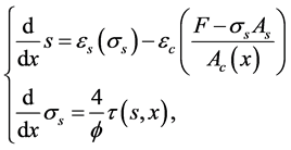
Combining Equations (2), (4) and (6), the following non-linear differential equation is obtained
 , (7)
, (7)
which can be solved, under appropriate boundary conditions, once input the stress-strain relationships for steel and for the tensile branch of concrete, the bond-slip law and the dependence of Ac on x.
2.2. Numerical Solution
To solve the non-linear Equation (7), the procedure described hereinafter can be implemented, based on the finite difference method.
It is worth to underline that the main difficulty in finding the solution concerns the assignment of the boundary conditions, since, in the present case, the boundary itself is unknown.
The most direct way to fix the boundary conditions is to assign the slip, s0, and its first derivative  in a cross section where sc = 0, typically corresponding to a cracked section or to an end section of the tie. Moreover, since in this section ec = 0, from Equation (6), it results
 , as soon as the steel strain es0 is assigned.
Since boundary conditions themselves depend on the strain field in the concrete tie, solution of Equation (7) requires an iteration process, like the one described hereinafter.
The proposed procedure is based on an iterative shooting solution of the system of ODEs
 (8)
(8)
suitably derived from Equation (7).
The first phase (phase I), summarized in the flow chart shown in Figure 2, allows to define the boundary conditions up to the first crack opening in a reinforced concrete tie, the length of which is L*, through the following steps:
1) set the origin of the x-axis in the starting cross section x = x0 = 0, which coincides with an end section of the tie, where sc = 0, and subdivide the half of the tie in N intervals of constant length Dx;
2) assign the s-e constitutive laws for steel and for concrete under tensile stresses; assign the bond-slip law, τ-s; assign the Ac(x) function;
![]()
Figure 2. Flow chart of the proposed numerical procedure up to the first crack opening.
3) set i = 1, assign tentatively the boundary conditions in x = 0, s0 and  or equivalently s0 and es0, being
 , and, using the bond-slip law and the steel constitutive law, evaluate the bond stress τ0(s0) and ss0(es0);
4) starting from  integrate (8) using for instance the Runge-Kutta 4th order method, and determine the slip si and the steel stress ss,i at the end of the interval, xi;
5) using the bond-slip law, evaluate the bond stress τi(si) in xi;
6) using the equilibrium condition (3) of the tie segment, calculate , through the general equation
![]() (9)
(9)
where Ac,i is the concrete area at section xi, and ρi the geometric steel to concrete ratio at the i-th section;
7) stop the iteration when si = 0, and consequently τi = 0, or when i = N and check convergence (step 9);
8) set i = i + 1 and iterate the process from step 4;
9) check convergence: if condition es = ec is satisfied at xi, convergence is achieved; otherwise keep unchanged the value of es0 and assign a new value for s0, iterating the process from step 6 till to convergence;
10) once the convergence is achieved, retain the actual value of s0(es0) and the corresponding real curves es(x) and ec(x) along the tie, together with the actual transfer length La(es0), as shown in Figure 3.
Of course, the searching of s0 can be refined using one of the usual numerical root finding methods, like the secant method, the false position method or the Newton-Raphson method.
Considering that actual values of s0(es0) and es0 represent the real boundary conditions at x = 0 when the stress in the naked bar is ss0(es0), the actual boundary conditions can be derived, in terms of es0 and s0, in the whole significant range of the loading process, simply increasing es0 and iterating again the procedure.
Clearly, in the loading process described by the increase of es0, the strains es and ec at x = La and the transfer length La itself are increasing functions of es0.
As soon as the concrete ultimate tensile strain ect is attained, for![]() , setting
, setting ![]() and
and ![]() and, provided that the condition for crack formation,
and, provided that the condition for crack formation,
![]() , (10)
, (10)
is fulfilled, a first crack opens at![]() , satisfying the inequality
, satisfying the inequality
![]() . (11)
. (11)
![]()
Figure 3. Typical distribution of steel and concrete strains in the uncracked tie for a given es0.
When the crack opens, the strain distributions es and ec on the length ![]() abruptly change and a discontinuity occurs in the s0-es0 diagram. The updated strain distributions as well as the updated slip value
abruptly change and a discontinuity occurs in the s0-es0 diagram. The updated strain distributions as well as the updated slip value ![]() can be then derived iterating the procedure for the unique case
can be then derived iterating the procedure for the unique case![]() , setting the tie length to
, setting the tie length to![]() , as described afterwards.
, as described afterwards.
As known, other cracks can form for es0 values slightly greater than the identified steel strain level ![]() until a steady situation is achieved in the whole tie. In this situation consecutive cracks are spaced less than 2
until a steady situation is achieved in the whole tie. In this situation consecutive cracks are spaced less than 2![]() , so that the condition sc < fct is satisfied in each point of the tie and the first crack pattern is fully stabilized.
, so that the condition sc < fct is satisfied in each point of the tie and the first crack pattern is fully stabilized.
The actual crack locations are generally indeterminate, as the tensile strength of concrete, fct, is a random variable and the unique constraint for ![]() is the inequality (11). In any case, the
is the inequality (11). In any case, the ![]() distances along the tie, and consequently the first crack pattern through the Monte Carlo method can be obtained, assigning, for example, a random concrete tensile strength distribution along the tie itself.
distances along the tie, and consequently the first crack pattern through the Monte Carlo method can be obtained, assigning, for example, a random concrete tensile strength distribution along the tie itself.
Nevertheless, even if the first phase crack is stabilized, further cracking is not prevented for increasing values of the external tensile force F. In fact, since the slip s increases as F, and τ depends on s, it can happen that concrete tensile strength fct is reached again for F = F(2) within a distance![]() ,
, ![]() , determining a new stabilized cracking pattern.
, determining a new stabilized cracking pattern.
The subsequent phases can be investigated properly modifying the above illustrated procedure. Referring to the j-th step, the modified procedure is summarized in the flow chart in Figure 4:
1) set the origin of the x-axis in the starting cross section x = 0 of the considered portion of the tie, bounded by adjacent cracks spaced![]() , and subdivide half of the interval in M parts of constant length Dx;
, and subdivide half of the interval in M parts of constant length Dx;
2) set i = 1, assign tentatively the boundary conditions s0 and![]() ,
, ![]() , at x = 0 and evaluate the bond stress τ0(s0) and ss0(es0), bearing in mind that, at the first step after the (j − 1)-th crack formation phase, it holds
, at x = 0 and evaluate the bond stress τ0(s0) and ss0(es0), bearing in mind that, at the first step after the (j − 1)-th crack formation phase, it holds
the equality![]() ;
;
3) assume the function s(x) is antisymmetric in the interval![]() : this implies that, disregarding friction forces, the convergence condition is met if the slip s vanishes at midpoint of the interval, where the concrete stress sc reaches the local maximum scmax, then solve Equation (7) as above (steps 3 to 9);
: this implies that, disregarding friction forces, the convergence condition is met if the slip s vanishes at midpoint of the interval, where the concrete stress sc reaches the local maximum scmax, then solve Equation (7) as above (steps 3 to 9);
4) as scmax increases with es0, a new crack opens at ![]() as soon as the strain es0 attains the value
as soon as the strain es0 attains the value![]() , corresponding to
, corresponding to![]() .
.
Set ![]() and iterate again the process from 1), until es0 attains the ultimate value, esu.
and iterate again the process from 1), until es0 attains the ultimate value, esu.
Finally, crack formation ends and the crack pattern is completely defined when, along the whole tie, it results sc < fct, whichever the value of es0. In the final stage, experimental evidence confirms that tension stiffening is negligible, so that tie behavior tends to fit the naked bar behavior.
Once completed the procedure, the evaluation of each crack width is trivial, being the sum of the quotas s0 pertaining to the two parts of the tie delimited by the crack.
At the end of each iteration step, as soon as convergence conditions are satisfied, the couple of boundary conditions, s0 and εs0, describing the evolution of the loading process, is finally obtained.
In Figure 5 a typical outcome of the procedure’s implementation is shown in terms of s0-es0 curve for the end cross section of a reinforced concrete tie, which has been previously investigated adopting the CEB-MC90 [12] bond-slip relationship illustrated in §3.3 [8] . The example is referred to a r.c. cylindrical tie reinforced by an axially located 16 mm B450C steel bar. The diameter of the tie, 0.8 m long, was 112 mm.
![]()
Figure 4. Flow chart of the proposed numerical procedure after the first crack opening.
![]()
Figure 5. s0-εs0 in a r.c. tie (ø 112 mm, 16 mm rebar) according to CEB bond- slip model [8] .
Inspecting the diagram, it is possible to identify the different phases of the loading path, the formation of cracks and in particular the discontinuities corresponding to the cracking phases: for the given ![]() the slip s0 at the crack location suddenly decreases, reflecting the abrupt redistribution of the strain fields in the concrete.
the slip s0 at the crack location suddenly decreases, reflecting the abrupt redistribution of the strain fields in the concrete.
3. Case Studies
To validate its effectiveness, the procedure has been to simulate the outcomes of two experimental test campaigns carried out by the authors [9] on full scale specimens of r.c. ties (case study 1) and by Bresler and Bertero [11] on similar specimens (case study 2).
Essentially, the actual (measured) strains on the steel reinforcing bars are compared with those obtained numerically by means of the proposed method.
It must be stressed that the classical CEB correlation is valid only when the directly loaded rebar is pulled out from a fully confined member, where the slip attains values of several millimeters, while in usual structures, like bending beams, the slip rarely exceeds 0.0 - 0.2 mm. This behavior can be explained considering that, due to tangential tensile stresses around the rebar, the concrete cover splits before full activation of bond strength (splitting failure mode).
Obviously, the splitting failure mode cannot be taken into account directly in one-dimensional bond-slip models, but its effects can be indirectly modeled by using effective bond-slip relationship, suitably determined. On the basis of this consideration, to widen the significance of the analysis and further corroborate the results, beside the classical CEB bond-slip relationship, an alternative effective bond-slip relationship, illustrated in §3.3, has been adopted.
3.1. Test Arrangements
The reinforced concrete ties we tested in [9] (case study 1) were made up by a single bar, 16 or 20 mm in diameter, axially located in a concrete cylinder, whose diameter was about 132 mm.
More in detail, the results obtained from “short specimens”, 235 mm long, are considered here. These specimens were setup to prevent the crack formation, in such a way to have the opportunity to check the accuracy of the procedure till to the appearance of the first crack, since the successive phases (cracked specimen) are the reiteration with different boundary conditions of phase I itself.
The strains along the steel bar were measured using electrical strain gauges, spaced 25 mm one another and embedded in two diametrically opposite milled grooves (3.5 ´ 4 mm) (Figure 6).
Moreover, the main objective of tests was the definition of a suitably improved effective local bond-slip relation law, alternative to the CEB ones, able to take into account indirectly the effects of the splitting failure mode on the actual non-linear behavior of reinforced concrete members.
Bresler and Bertero [11] performed similar tests on r.c. ties, axially reinforced by one single rebar (case study 2), again instrumented with strain gauges. In this case the strain gauges were located in a milled groove inner to the steel bar, previously cut in two halves and subsequently reassembled, according to a technique previously
developed by Mains [14] .
The results, which have been considered for the comparison, refer to cylindrical specimens, 406 mm long (16”), whose diameter was 152 mm (6”). The diameter of the reinforcing bar, placed axially, was 28.6 mm (1”1/8) (Figure 7).
Since the concrete cylinder presented a notch at midspan to predetermine the location of the crack, the analyses reported here refer to the half-length L/2.
Among the available data for case study 2, they have been selected those referring to the specimen “H” for the increasing branch of the load cycle nr. 2, which can be assimilated to a monotonic loading phase extending from 17.8 kN (4 kips) up to 133.4 kN (30 kips).
3.2. Basic Assumptions
In numerical simulations, constitutive laws for steel and concrete have been modeled according to the Ramberg- Osgood formulation [15] , in the form
![]() and, (12)
and, (12)
being fy the yield stress of the steel, fct the tensile strength of concrete, and as, n, ac and m the curve parameters.
The mechanical properties and the curve parameters pertaining to case study 1 were obtained suitably fitting the experimental data derived from ad hoc tests [9] , while in case study 2, due to lack of information, the limited available experimental data were used, appropriately adapting the parameters evaluated in case 1.
The actual yield stress of steel rebars was fy » 545 MPa in case 1 and fy » 690 MPa in case 2, while the compressive strength of concrete was fc = 29.6 MPa in case 1 and fc = 40.8 MPa, in case 2.
Furthermore, it has been assumed that the effective concrete area Ac(x) varied steeply from zero to Ac within a distance approximately twice the rebar’s diameter, according to an exponential law. Anyhow, sensitivity analyses showed that results do not vary significantly from those obtained assuming a constant value for Ac.
3.3. Bond-Slip Laws
As recalled above, a bond-slip correlation currently adopted in Literature is that proposed by the CEB in Model Code 90 [12] , slightly modified in the final draft of fib Model Code 2010 [13] . Inspecting the bond-slip laws proposed in Model Codes 90 and in Model Code 2010 for concrete class fc » 30 MPa (Figure 8), it results that, within the scopes of the present work, the differences between the two curves are not critical.
As discussed in [15] , the bond-slip curves proposed by CEB/fib, in particular in the field where bond deteriorates, are associated with slip values well beyond values actually measured in r.c. members, where rebars are efficiently anchored. Moreover, as said before, these values would be incompatible with effective crack widths currently measured in real structures, which are directly correlated with actual slip values.
Consequently, as clearly demonstrated by the implementation of the procedure too, the adoption of CEB τ-s laws implies that the maximum level of bond stress cannot be attained in real structures, so that the decreasing right branch of τ-s curve, associated with bond deterioration, cannot be covered.
On the basis of the refined measurements of steel stress, carried out on the above mentioned r.c. ties during monotonic tensile tests [9] , an alternative effective bond-slip relationship can be proposed. The discussion of criteria adopted to derive this law, which is illustrated in Figure 9, again for a fc » 30 MPa concrete, is out of the
![]()
Figure 8. CEB-MC 90 and fib MC2010 bond slip models for concrete (fc » 30 MPa).
![]()
Figure 9. Proposed effective bond-slip model for concrete (fc » 30 MPa).
scope of the present work; nevertheless, however it must be highlighted that the maximum bond stress (which is the same adopted in CEB-FIP models) is associated to a slip value which is significantly lower than the corresponding ones in MC90 and in MC2010 models.
3.4. Discussion of Results
Using the proposed procedure, the behavior of the two ties tested in case studies 1 and 2 have been simulated, for increasing value of the external force applied to the rebar. For selected load steps, chosen to appropriately cover those for which experimental data were available, the results are summarized in Figure 10 and Figure 11, pertaining to case study 1 and case study 2, respectively.
In the diagrams, for each load step, the curves representing the measured experimentally strain distributions e-x along the steel bar are compared with those obtained by the implementation, in turn, of the bond-slip correlation suggested by the CEB Model Code 90 (Figure 8) and of the alternative effective bond-slip law suggested in Figure 9. In order to facilitate the comparisons, in the figures the curves obtained adopting CEB model, designated as “CEB”, are plotted in grey, the curves obtained adopting the alternative model, designated as “A”, are plotted in black and finally the experimental ones are plotted with piecewise linear curves.
Aiming to supplement the information, the three families of τ-x experimental and numerical curves, describing the bond stress variation along the tie in case 1, are reported in Figure 12. The diagram clearly shows that, as expected, CEB model excites very low bond stresses.
Inspecting the diagrams it can be remarked that, in both cases, the proposed procedure allows to perform refined local investigations and that, even if outside the scope of the present paper,
![]()
Figure 10. Measured and calculated ε-x curves (case 1 [9] ).
![]()
Figure 11. Measured and calculated ε-x curves (case 2 [11] ).
![]()
Figure 12. Measured and calculated ε-x curves (case 2 [11] ).
· the use of CEB bond-slip model leads to underestimate the bond stress transfer from steel to concrete; in fact, the calculated strains in the rebar are markedly higher than those actually measured and the calculated bond stress are sensibly smaller than the actual ones;
· on the contrary, the use of the bond-slip model proposed in [9] leads to a good fit of bond stresses and of measured steel strains;
· moreover, the slip values calculated adopting the two alternative τ-s models at end sections of the tie do not fully reflect the significant differences registered above; in fact in both cases maximum slips are limited to 0.2 mm; but, in case of CEB correlation, these values are one order of magnitude lower than the slip interval associated with the plastic range of the bond-slip CEB curve. This confirms that, as just explained, in r.c. members actual slips are well below those corresponding to the horizontal plateau or to the descending branch of CEB curves.
4. Conclusions
A numerical method for the study of the evolution of the crack pattern in r.c. ties, under monotonic loading, simulating the tensile part of a more general r.c. member in bending, has been illustrated.
As soon as the stress-strain relationships for steel and concrete in tension are given and a suitable effective bond slip model is adopted, the method allows to calculate the actual distributions of steel and concrete strains and stresses along the tie and, consequently, the actual distributions of bond stresses and slips between the steel reinforcement and the surrounding concrete.
A comparative implementation of the procedure is discussed with reference to the CEB bond-slip model and to an alternative effective bond-slip model, derived from experimental results obtained in a previous experimental study on concrete ties reinforced with instrumented rebars.
The numerical simulations of the ad hoc tests as well as of other similar experimental data available in Literature, confirmed that the proposed algorithm is satisfactory and can be suitably adopted for refined non-linear analyses of r.c. ties, whichever the bond-slip model taken into account.
The numerical procedure can be easily extended, with slight modifications, to more general cases, like beams in bending or beam to column joints, in particular when refined and realistic evaluations of the actual behavior are required.