Two Low Profile Unbalanced Fed Inverted L Elements on Square Conducting Plane for MIMO Applications ()

1. Introduction
The demand for high data rate and large channel capacity of users in recent mobile communication systems drives the MIMO systems as the subject of investigation for several years [1] . A practical MIMO antenna should have a low signal correlation between antenna elements and good impedance matching characteristics [2] [3] . The mutual coupling is an important factor when antennas have been used for MIMO applications [4] [5] . Higher mutual coupling may result in lower antenna efficiencies and higher correlation coefficients. The effect of mutual coupling on the capacity of MIMO wireless channel was studied in [6] . One of the most critical parameter affecting mutual coupling and correlation is the spacing between antenna elements. Analytical studies have shown that the distance between typical antenna elements such as dipole antenna needs to be at least half wavelengths for minimal or no mutual coupling [7] . However, since the distance is limited due to the small area which the elements are placed, especially at the portable MIMO-enabled devices, the MIMO antennas should be designed as small as possible. This is more conspicuous when MIMO antennas will be used in small terminal devices and more effort will be devoted to devising new MIMO antenna elements with compact and reasonable antenna characteristics [8] -[10] . The authors have proposed the unbalanced fed, ultra low profile inverted L antenna on a rectangular conducting plane for mobile terminal devices [11] [12] . When the size of conducting plane is 0.245 λ (λ: wavelength) by 0.49 λ and the antenna height is λ/30, and the length of horizontal element is around a quarter wavelength, the input impedance of this antenna is matched to 50 Ω and its directivity becomes more than 4 dBi. In this antenna, the electromagnetic field is strongly excited between the inverted L element and the conducting plane. Therefore even though two inverted L antennas are closely located, the mutual coupling may be weak.
Several other designs of MIMO antenna satisfy for the requirement of MIMO systems; unfortunately these antennas have limitation of size for practical MIMO application. Also in general, MIMO antennas consist of complicated structures [13] -[18] . For example, in [17] , two meandered monopoles with a gamma matching and a folded T-shaped stub between radiators are printed on an FR4 substrate with its size of 30 mm by 15 mm. Its directivity is less than 0 dBi. In this paper, the very simple antenna composed of two unbalanced fed, ultra low profile inverted L antennas on a square conducting plane with its size of 55 mm is proposed as MIMO antenna applications [19] . In the numerical analysis, the electromagnetic simulator WIPL-D based on the Method of Moments is used [20] .
2. Antenna Structure
Figure 1 shows the structure of the proposed antenna. Two identical low profile inverted L antenna elements with the height h = 4 mm are mounted on the square conducting plane with its size of 55 mm by 55 mm. The antenna size corresponds to 0.45 λ by 0.45 λ by 0.03 λ at the design frequency of 2.45 GHz. The antenna elements are composed of the semi rigid coaxial cable with outer and inner radius 1.095 mm and 0.255 mm, respectively. The inner conductor of the coaxial cable is extended from the end of outer conductor, that is, each antenna element is excited at the end of outer conductor. The distance d between two antenna elements are investigated in order to reduce the mutual coupling. Furthermore the distance is challenged to be less than half wavelength. Both the distance pym between the vertical element to the back edge of the ground plane and distance pyp between the vertical element to the front edge are fixed as 10 mm and 45 mm, respectively. In each case of the distance between two antennas, the length of horizontal elements L and L1 are optimized to achieve impedance matching at the center frequency of 2.45 GHz. Figure 2 shows other arrangements of antenna elements.
3. Results and Discussion
In the calculation, the distance d between two inverted L antennas is changed from 30 mm to 45 mm. Table 1 shows the calculated return loss bandwidth larger than 10 dB, S21 and the directive gain in the z direction at 2.45 GHz for the different distance d between two inverted L elements. Figure 3 shows calculated S parameters of the optimized proposed MIMO antenna arrangement-1 for different distance d between two antenna elements. S21 becomes smaller than −20 dB as the distance d become longer than 41 mm.

Figure 1. The structure of proposed antenna; arrangement-1 (pym = 10 mm, pyp = 45 mm, h = 4 mm).
 (a) (b)
Figure 2. (a) Arangement-2; opposite parallel and (b) arrangement-3; face to face perpendicular arrangements.

Figure 3. Calculated S parameters of proposed antenna for different d (arrangement-1, h = 4 mm, pym = 10 mm, pyp = 45 mm).
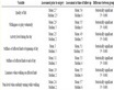
Table 1. Calculated return loss bandwidth, S21 and directivity for different distance between two antennas d (arrangement-1).
Table 2 shows the calculated return loss bandwidth, S21 and the directive gain in the z direction at 2.45 GHz for different antenna height h. When the height of antenna is increased, both the length of horizontal elements L and L1 become shorter. This means that the resonant frequency is determined by the total length of horizontal and vertical elements. Figure 4 shows calculated S parameters of the proposed MIMO antenna arrangement-1 for different antenna height h. The return loss bandwidth and S21 become smaller as the antenna height h becomes smaller. As the antenna height becomes smaller, the electromagnetic field concentrates near the excited antenna element. Therefore the return loss bandwidth becomes narrower and the mutual coupling between two antennas becomes weak.
Table 2. Calculated return loss bandwidth and directivity for different antenna height h (arrangement-1).

Figure 4. Calculated S parameters of proposed antenna for different h (arrangement-1, d = 41 mm, pxp = 7 mm, pym = 10 mm, pyp = 45 mm).
Figure 5 shows the return loss bandwidth larger than 10 dB and the directive gain in the z direction at 2.45 GHz of the proposed MIMO antenna arrangement-1 for different distance d between two antenna elements and for different height h of antenna. Both the directive gain and the return loss bandwidth become larger by extending the distance between two antennas.
Figure 6 shows the directive gain in the z direction at the proposed MIMO antenna arrangement-1. Figure 7 shows the current distribution of proposed MIMO antenna arrangement-1 at 2.45 GHz. The inverted L element-1 is excited and the element-2 is terminated with 50 Ω load. The large surface current is induced near inverted L element-1, on the other hand weak surface current is induced on the element-2 at resonant frequency of 2.45 GHz. This means that the good isolation between two elements is achieved.
Figure 8 shows the electric field radiation patterns on zx plane, yz plane and xy plane of the proposed MIMO antenna arrangement-1 at 2.45 GHz when inverted L element-1 is fed and inverted L element-2 is terminated by the matching load 50 Ω. The peak gain of antenna-1 is 4.12 dBi. The current distribution on the inverted L antennas in the y direction and the surface on the conducting plane in the x and y directions contribute to the radiation. Therefore there are no deep nulls in any direction, although omnidirectional polarization antennas are used in general.
Figure 9 shows the near field distributions in the zx plane including feed points of arrangement-1, in the zx plane including the feed point of element1 of arrangement-2, and in the yz plane including feed point of element-2 of arrangement-3 at 2.45 GHz.
Figure 10 shows the near field distributions in xy plane including horizontal elements of each arrangement at 2.45 GHz. The good isolation is achieved in the balanced structure as proposed MIMO arrangent-1. Whereas, it can be seen that two elements are highly coupled to each other at arrangement-2 and arrangement-3.
From Figure 7, Figure 9 and Figure 10, in the case of proposed MIMO antenna arrangement-1, the surface current on the conducting plane between two antennas is small and the electromagnetic field becomes weak near

Figure 5. Return loss bandwidth and directive gain in z direction at 2.45 GHz (arrangement-1; pxp = 7 mm, pym = 10 mm, pyp = 45 mm).

Figure 6. Calculated directive gain at z direction (arrangemet-1; pxp = 7 mm, pym = 10 mm, pyp = 45 mm, h = 4 mm, d = 41 mm).

Figure 7. Calculated current distribution at frequency of 2.45 GHz (arrangement-1; h = 4 mm, d = 41 mm, pxp = 7 mm, pym = 10 mm, pyp = 45 mm, L = 31.2 mm, L1 = 21.4 mm).

Figure 8. Simulated electric field radiation pattern of proposed antenna at 2.45 GHz (arrangement-1; h = 4 mm, d = 41 mm, pxp = 7 mm, pym = 10 mm, pyp = 45 mm, L = 31.2 mm, L1 = 21.4 mm).

Figure 9. The near field distribution at 2.45 GHz (h = 4 mm, d = 41 mm, pxp = 7 mm, pym = 10 mm, pyp = 45 mm, L = 31.2 mm, L1 = 21.4 mm).
the conducting plane between two antennas. This means that the mutual coupling is mainly not by the current flowing on the conducting plane but by the spatial coupling.
Figure 11 shows the reflection coefficients of three arrangements. The placement of inverted L elements as arrangement-1 obtains the best isolation between two elements.
Figure 12 shows the calculated and measured S parameters of proposed MIMO arrangement-1. The fairly good agreement between calculated and measured results is obtained.
The correlation coefficient of the proposed MIMO antenna is calculated through S parameter. The correlation coefficient ρe of a two element inverted L antenna system can be calculated by the following equation [21] ;

Figure 10. The near field distribution on horizontal elements of xy plane at 2.45 GHz (h = 4 mm, d = 41 mm, pxp = 7 mm, pym = 10 mm, pyp = 45 mm, L = 31.2 mm, L1 = 21.4 mm).
 (1)
(1)
Figure 13 shows calculated and measured correlation coefficient of the proposed MIMO antenna arrangement-1. The correlation coefficient becomes less than 0.02, which means that the proposed antenna has good

Figure 11. Reflection coefficients of proposed antenna with different arrangements (h = 4 mm, d = 41 mm, pxp = 7 mm, pym = 10 mm, pyp = 45 mm, L = 31.2 mm, L1 = 21.4 mm).

Figure 12. Calculated and measured S parameters of the proposed MIMO antenna (pxp = 7 mm, pym = 10 mm, pyp = 45 mm, h = 4 mm, d = 41 mm).

Figure 13. Calculated and measured correlation coefficient between two inverted L antennas (arrangemet-1; pxp = 7 mm, pym = 10 mm, pyp = 45 mm, h = 4 mm, d = 41 mm).
diversity gain when antenna height and the distance between inverted L elements are 4 mm and 41 mm, respectively.
4. Conclusion
The MIMO antenna, composed of two unbalanced fed, ultra low profile inverted L antenna elements, has been proposed. Two inverted L elements are parallel located on the square conducting plane with its size of 045 λ by 0.45 λ. The height of inverted L antennas is 0.03 λ, and the distance between two inverted L antennas is 0.34 λ. With a very simple structure, the antenna has the good performances. The calculated and measured return loss larger than 10 dB is 2.41 to 2.50 GHz and 2.44 to 2.53 GHz, respectively. The directive gain is 4.12 dBi. The proposed antenna is promising for MIMO application systems.
Acknowledgements
Erfan Rohadi would like to thank to the General of Higher Education, Ministry Education and Culture of Republic Indonesia for providing the scholarship of the doctoral course program.