1. Introduction
Superplasticizers (SP) are the most important admixtures used in concrete production to avoid rapid cement particles flocculation, to allow convenient mixture workability time and to reduce water-cement ratio [1]. Despite their performance, the way they act and the interactions they have with the particles surface are not completely cleared yet, specially referring to the polycarboxylic dispersants with comb-shaped structure (PCP).
The activity of dispersing polymer is not limited only to the deflocculation of cement particles; as described in literature for some types of organic substances, they can also influence the formation of the cement hydrated phases changing the hydration rate [1-5].
SPs are reported to affect both the kinetic of formation and the morphology of the C3A hydrated species as they modify the ettringite crystal dimensions [6]. Then, looking at the other cement phases, SPs influence the reactions of C3S too by delaying its hydration to C-S-H, so retarding the setting time of cement paste [7,8].
However the comprehension of the formation mechanisms of hybrid organic-inorganic structures from the interaction of the admixtures with the inorganic surface is a severe task due to the simultaneous hydration processes of different mineral phases and the high number of reactions. Similarly the side effects on the kinetic of cement setting and hardening are difficult to rationalize. To investigate all these aspects it is necessary to simplify the cementitious system by studying suitable models as matrixes, such as the following:
• Tricalcium aluminate (C3A), the most reactive of the Portland clinker phases;
• Tricalcium silicate (C3S), responsible for setting and development of cement early strength.
In this work, the C3S phase was selected, which is the most abundant compound in Portland clinker.
It was assumed that the key-factor influencing the polymer dispersing activity and the cement hydration is the conformation of the polymer structure in proximity of the surface of the matrix. The investigation was conesquently directed towards the study of the interaction of the polymer with the C3S substrate at different times. In particular the study examined the effect of the two main structural parts of the PCP, i.e. the backbone and the side chain, on hydration and morphology of the substrate.
For this purpose a linear polymer was synthesized consisting on one side of a 4 carbon short chain (Succinic Acid, after named SA) with a polar linking site (free carboxylic group) suited to interact with the Ca2+ ions of the inorganic surface, and, on the opposite side, bonded through an ester linkage to a long ethylene oxide chain terminated with the O-CH3 group (MPEG; Mw = 1000).
The polymer was characterized by NMR, FT-IR and carboxylic group titration. The model polymer was tailored in order to represent the grafted repetitive unit of a typical commercial comb-polymer (PCP).
2. Materials and Methods
2.1. Admixtures and Synthesis
The organic materials for this research were: a comercial comb-type polymer PCP (Mw = 32,500 Da, MPEG Mw = 1000 Da, esterification degree = 30%); a linear model poly(ethylene glycol) methyl ether succinate (PEOSA1000) synthesized “ad hoc” and a polyacrylic acid (PAA; Mw = 5000 Da) partially neutralized with NaOH at pH = 4.
The PCP polymer, partially Na-salified, has a linear backbone constituted by a PAA (Mw = 5000 Da), with carboxylic groups partially grafted with mono-methoxy terminated polyethylene glycol (MPEG Mw = 1000 Da). The polymer solution was acidified to pH 1 by HCl 1 M, then it was extracted from the aqueous phase by liquidliquid separation with chloroform and finally the resulting polymeric wax was treated with hexane in order to remove the residual chloroform by azeotropic distillation (Figure 1(a)).
1H NMR of PCP (DMSO) shows the following signals: δ 4.2 (m, 2H, -COOCH2-), 3.7 - 3.3 (m, n*4H, (-CH2- O-CH2-)n of the PEG), 3.2 (s, 3H, -OCH3), 1.8 - 1.4 (m, 1H, (-CHCOOR-) of PAA where R is MPEG or H). PEOSA1000 was synthesized by selective esterification following the scheme shown in Figure 1(b) using succinic anhydride and pyridine, and mono-methoxy terminated poly(ethylene glycol) (Mw = 1000 Da), purchased from Aldrich Chem. Co and used as received. 1H NMR of PEOSA1000 (DMSO) shows the following signals: δ 4.2 (m, 2H, -COOCH2-), 3.7 - 3.3 (m, n*4H, (-CH2-OCH2-)n of the PEG), 3.2 (s, 3H, -OCH3), 2.48 (m, 4H, (-CH2)2 of succinic acid).
2.2. Substrate and Mixtures Preparation
Samples of Portland cement (CEM I 52.5R), all from the same lot, were used as reference material for the study of the effect of the polymer on hydration rate. The chemical composition, express in percentage oxide, and some physical characteristic of cement are reported in Table 1.
The Figure 2 presents the granulometric distribution of the CEM I 52.5R powder. The mineralogical composition of phases that constitute the cement, according to Rietvield method, is reported in Table 2.
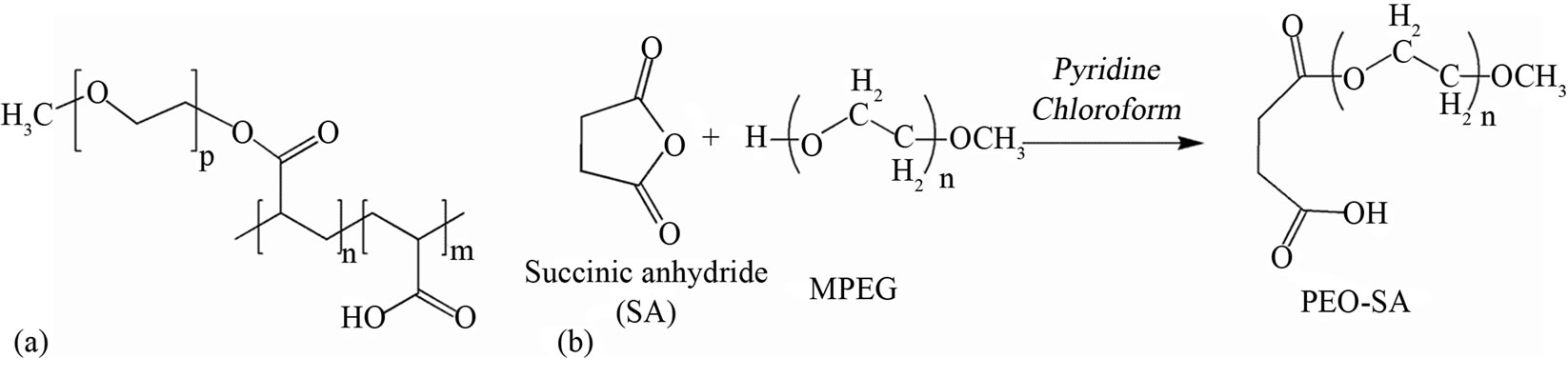
Figure 1. Structural schemes of (a) superplasticizer (PCP) and (b) PEOSA1000 unit that simulates the side chain of PCP.
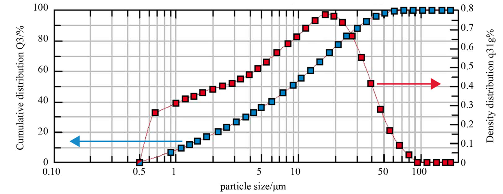
Figure 2. Particle size distribution of the CEM I (red curve, right y-axis) and cumulative distribution (blue curve, left y-axis).

Table 1. Physical and chemical data of the CEM I.
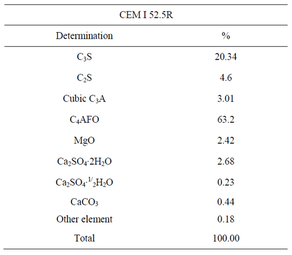
Table 2. Mineralogical composition of the CEM I according to Rietveld.
C3S was synthesized from CaCO3 (Prolabo RP Normapur) and SiO2 (Aerosil, Evonik GMBH). The synthesis was done by mixing the raw materials and the water with a Hobart mixer for about 15 minutes. The mixture was then submitted to a proper temperature program (two steps: first from 80˚C to 1000˚C, second to 1555˚C. The temperature was increased at 5˚C/min and the sample was maintained at 1555˚C for two hours).
At the end of the thermal treatment, the C3S was quenched, then ground to a fineness of 3190 cm2/g (Blaine Specific Surface) and finally characterized by XRD analysis (Figure 3). The XRD composition indicate a CaO/SiO2 = 3.026 and a free CaO = 1%. The powder was investigated at different hydration times (after the contact with the water) by conduction calorimetry and by SEM.
Four different pastes for each substrate, C3S and CEM I, (W/C = 0.4) were prepared for the conduction calorimetry test: a blank paste made with deionized water, two pastes made with the polymer solutions containing PEOSA1000 and PCP at 0.30% by weight dosage on dry matter, and a paste made with PAA. In the last paste PAA moles were calculated at the same number of free carboxylic groups that in the PCP solution which means around 80% less in weight. The code and the description of the tests are reported in Table 3.
The hydration reaction of the C3S paste was blocked at 7 h and 7 days, with a methanol/acetone 1:1 solution (5’ contact time), in order to obtain stable, not further reacting samples. The suspended powder was filtered off and dried under vacuum (3 × 10⁻² mbar) for 5 h. The samples blocked with solvent were used only for the SEM analysis. Being all the samples (blank paste and C3S/admixture) treated in the same manner, the observed differences among them are significant and attributable only to the interaction of the matrix with the organic compound.
2.3. Instruments
The average molecular weight of the PCP polymer was measured by GPC-TDA (Viscotek TDA) equipped with refractive index, viscometer and right angle light scattering (RALS).
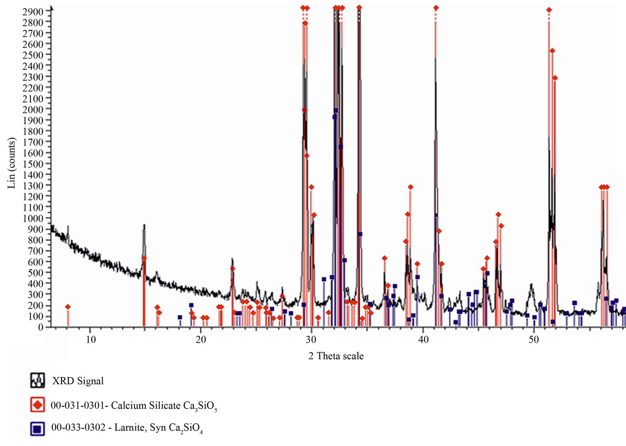
Figure 3. XRD of the synthesized C3S with database signals corresponding to the pure C2S (■) and C3S (♦).
The portlandite growth and the C3S structures were checked by X-ray powder diffraction using a Philips PW1130 equipment with copper cathode.
The shape, size and aspect of the portlandite particles were observed by scanning electron microscopy (SEM) using a Stereoscan 360, equipped with a backscattered electron detector, Leica Cambridge Instruments, Cambridge, UK. Before SEM analysis the C3S powder of the eight samples was dried under vacuum and coated with gold by sputtering technique (Sputter Coater SC7640; Polaron, Hertfordshire, UK).
2.4. Adsorption Isotherm
Pastes were prepared by mixing cement (CEM I 52.5R), water and polymer (PEOSA1000 and PCP). W/C ratio was 0.4. The polymer concentration analyzed was 0.3% (dry matter by weight of cement) for adsorption test. The mixing was made by an IKA stirrer running for 3 minutes: one minute at 150 rpm and then two minutes at 500 rpm. The paste was put into a test tube and stirred for 15 minutes. Then the paste was centrifuged by a HERAEUS-CHRIST Labofuge I for 20 minutes (2000 rpm). The liquid was filtered with a 0.20 µm PTFE filter, diluted in pure deionized water, acidified by phosphoric acid (final pH < 3) and analyzed by TOC technique (Total Organic Carbon) using a Shimadzu TOC-5050 A. Adsorption isotherms were obtained at 20˚C after 15 minutes of liquid-solid contact to avoid the ester hydrolysis in basic environment. After filtration the interstitial water was diluted ten times and analyzed (20 g).
The amount of carbon in TOC analysis comes from the polymer and the cement. To eliminate the contribution of cement the following calibrations were performed:
• Superplasticizer (SP) calibration;
• Cement blank test calibration;
• Polyethylene glycol methyl ether (MPEG) calibration.
The error induced by not reacted MPEG (MPEGfree) was eliminated by using carbon signal and amount of MPEGfree present in the superplasticizer (calculated by 1H-NMR).
The weight of polymer adsorbed on cement mass was transformed in moles and number of carboxylic acid on moles, in order to better investigate the role of the linking site on the morphological modification induced by the organic compound.
3. Results and Discussion
3.1. Thermal Analysis
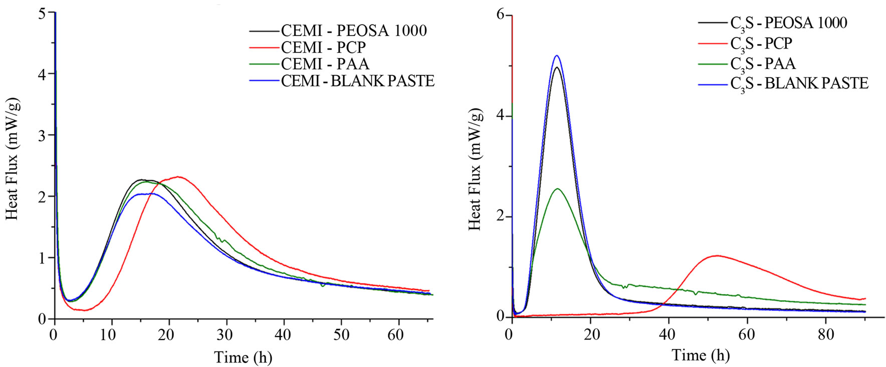
CEM I pastes The results of thermal conduction experiments on CEM I pastes (Figure 4(a)) show that only the PCP induces significant hydration delay. The delayed measured by conduction calorimetric is about 6 h. It was measured at the intersection point between the tangent to the curve and the baseline at the first and main peak of the silicates. The hydration delay is ascribed neither to the PAA backbone, nor to the MPEG side chain. Analyzing the heat flux curves (mW/g), the paste prepared with PAA and PEOSA1000 present the same behavior of the CEM I blank paste. It follows that the delay of C-S-H formation has to be attributed to the whole structure of the PCP and not at one single structural parts of comb-polymer. In this case the PAA and the MPEG that it should behave as the PEOSA1000 in reason of its structural affinity except for the linking site don't retard the hydration process.
It is well-known that superplasticizers produce a remarkable positive deflocculation of the cement particles but also a collateral negative delay of the initial hydration reactions [1,9]. Anyway superplasticizers prevent the agglomeration of the particle and should facilitate the access to water/nutrients and facilitate the reactions of hydration.
The first step of the process is the adsorption of the polymer that obstacles aggregation/agglomeration of the particles and prevents the aqueous nutrient from reaching the cement surface.
Examining the adsorption behaviors, more moles of PEOSA1000 polymer are adsorbed on cement than the PCP polymers at equal number of initial added moles (Figure 5) [10]. In agreement with the literature, at early age of adsorption the low molecular weight polymers adsorb better than high molecular weight [11,12]. As expected, the comb-polymers -COOand MPEG groups (each one calculated on the base of adsorbed polymer) are more numerous than the linear one. Consequently the hydration delay may be attributed to the characteristic of the PCP structure. According to Mollah et al. [13] the dispersing chain are forced to stay close each other by the action of the backbone, that having numerous -COOgroup could strongly adsorb on the cement surface. As a consequence the lowest energy conformations of the MPEG branch may be organized as in a helix [14]. This geometry facilitates the establishment of calcium metal organic complexes with MPEG as chelating part. It is indeed known that the ether groups of PEG coordinate metals cations acting like crown ether [14-19]. Then the helicoidal conformation of the side chains of PCP may obstacle the ions flux blocking the stream towards the surface, indispensable to the crystals growth. This behavior does not appear with the PEOSA1000 polymer where the backbone effect on the PEO there not exists and the chain assumes an expanded conformation [20].
C3S pastes Generally the cement is consisting of: 5% - 10% C3A, 50% - 70% C3S, 15% - 30% C2S, 5% - 15% C4AF, and 3% - 8% other additives or minerals (such as oxides of calcium and magnesium). So the C3S is the mayor phase in cement. Then it is possible to hypothesize the same behavior of PCP on C3S like on CEM I paste.
To better analyze this effect the attention was focused on the main silicate phase, C3S. The hydrated phase of C3S (C-S-H) is the one that influence greater the mechanical properties of cement [21]. Samples of pure C3S with triclinic form were synthesized “ad hoc” and the XRD spectra were in good agreement with the C3S database reference (Figure 3).
With this matrix only the PCP induces remarkable hydration delay quantifiable in about 30 h (Figure 4(b)). On this phase the PAA, i.e. the PCP backbone, and the PEOSA1000, i.e. the isolated MPEG chain terminated with the COOH linking site, do not induce any apparent hydration delays (time axis). As show in cement, also in this case the hydration delay of C3S is due to the PCP polymer. This phenomenon could be attributed to the polymer structure: the side MPEG chains could force to stay each other by the backbone assuming a helicoidal conformation. Some interesting consideration can be done observing the cumulative heat curve reported in Figure 4(c). The cumulative heat developed by the C3SPAA paste is lower than that product by the C3S blank pastes and C3S-PEOSA1000 but is higher than C3S-PCP. Examining the cumulative heat developed during the first 30 h of hydration, it could be possible observe that C3S-PAA and C3S-PEOSA1000 have already developed heat (the hydration reaction is started) while the C3S-PCP have not product heat. The hydration reaction of C3SPCP starts after 30 h.
So, it results definitively that the PAA backbone of the PCP has greater influence than the PEO branches (PEOSA1000 in the case) on the heat flux during the C3S hydration. Moreover, according to the literature data [10, 22], the same experiments carried on C3A show different thermal behavior comparing the C3A-PCP and the C3APAA mixtures. Also in this case the organic compounds reduce the heat flux produced during the hydration.
3.2. Surface Morphology Modification
Portlandite growth was checked by X-ray diffraction. Both portlandite and non-reacted C3S are present in all the analyzed samples (Figure 6) after 7 days implying a not complete hydration. SEM microphotographs enhance the effects attributable to the admixture adsorption on the
 (a)
(a)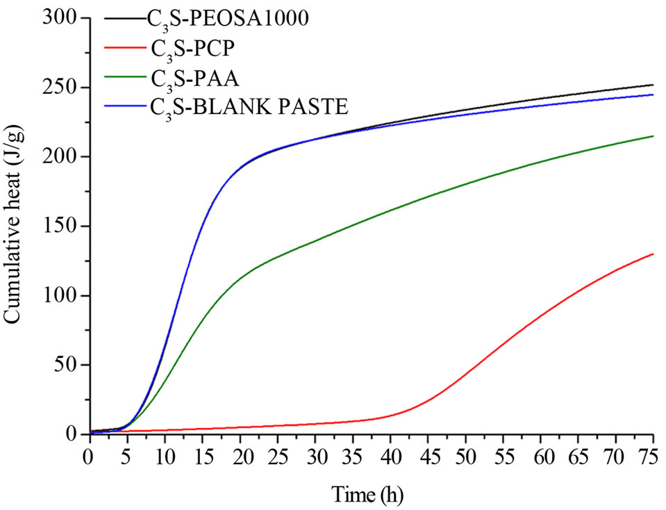 (b)
(b)
Figure 4. Heat flux of CEM I pastes and C3S pastes ((a) and (b)) and cumulative heat of C3S pastes (c).
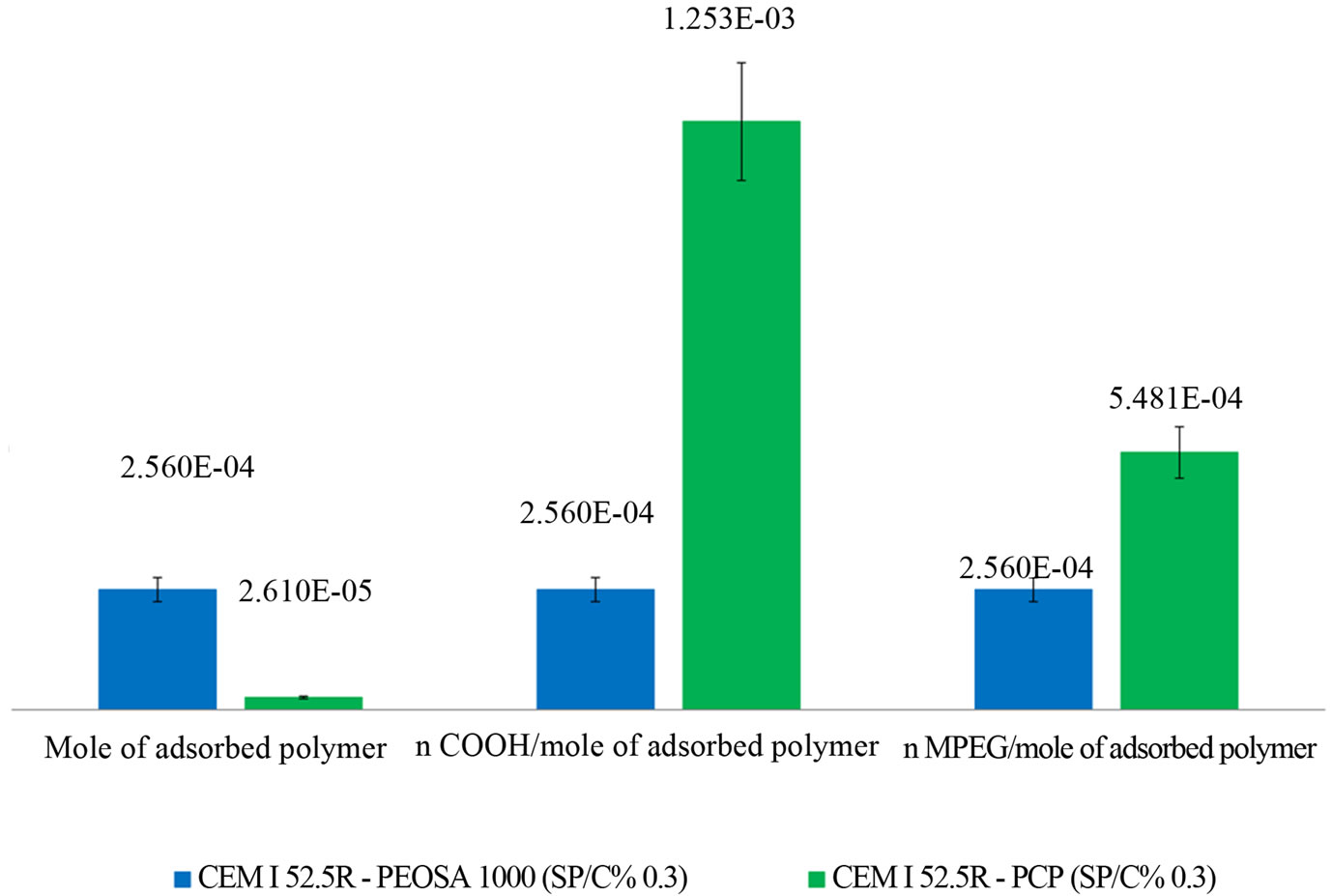
Figure 5. Adsorptions of PEOSA1000 and PCP on CEM I paste.

Figure 6. XRD Comparison of the XRD spectra of the systems C3S/PEOSA (a), C3S/PCP (b), C3S/PAA (c) after 7days. C3S (■), Portlandite (●).
growing hydrated phases. After 7 hours (Figure 7(a)) both the C3S/PEOSA1000 and the C3S/PAA pastes have very similar surface pattern: large and well-shaped solid structures are present on their surface. Comparing these
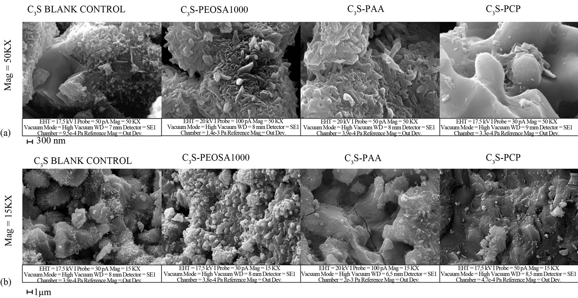
Figure 7. Comparison of SEM micrographs between hydration products of C3S paste without polymer and with polymer (PEOSA1000, PAA and PCP) after 7 hours from the beginning of the hydration reaction (a). The same after 7 days (b).
pastes with C3S blank surface it is possible observe the presence of a wider population of smaller parts. However the structures present on C3S/PAA are larger and more pronounced, and the surface is more jagged. The PCPtreated sample shows a significant presence of hydrated non-crystalline material, probably low crystalline C-S-H (Figure 7(a)). The hydration initial rate seems to be inversely related to the amount of low crystalline C-S-H:
C3S blank paste > C3S/PEOSA1000 > C3S/PAA > C3S/ PCP.
Analyzing the samples after 7 days, (Figure 7(b)) from the left to the right, we observe a very intense concentration of short small crystals1 on the C3S blank paste. The crystal population present on the C3S-PEOSA1000 seems to have greater dimension. Furthermore the C3S/PAA sample has a less defined structure with scarcely distinguishable organization (furrows, lines, plates) and very few acuminated and short crystals that are nearly absent on the C3S/PCP sample. The increasing of the dimension of the structures on the surface might be related to the behaviors observed in the calorimetric tests (Figures 4(b) and (c)). Specifically referring to the 7 days microphotographs, the lower heat fluxes and cumulative heat of the mixes prepared with the PAA and the PCP might be the cause of the larger dimensions of the crystals. On the contrary the density of fine structures seems to increase in the mixtures with the higher heat fluxes and cumulative heat. In conclusion the hydration developing rate influences the crystal morphology.
4. Conclusion
In order to analyze the effect of the PCP structure, the two parts that composed the polycarboxylate polymer are separately studied: i.e. a PEOSA1000 polymer (ad hoc synthesized) that is similar to the MPEG branches, and the PAA that is the backbone. The hydration of pastes based on C3S and CEM I with different admixtures was investigated by monitoring the thermal behavior. Considering both the matrixes, it appears that only the PCP, that combines in the same structure the backbone (PAA) and the side chain (MPEG), deeply defers the heat flux during the hydration. On the other hand, the single parts (i.e. PAA and PEOSA1000) seem not to delay the hydration. The PAA backbone appears more efficient to delay the development of the heat. Nevertheless the PAA backbone reduces the cumulative heat until 75 h in the C3S hydration. The observation seems also supported by the SEM comparison of the modifications induced by the polymer. Large low crystalline C-S-H structures are observed when large heat delay is measured. Therefore, it brings the result that the structures of the polymers play an important role in crystal growth through the influence on the hydration kinetic. The thermal effects might be related to the crystals morphology as it depends on the quantity and the rate of the “nutrient ions” reaching the surface. Considering the adsorption data, metal organic complexes are hypothesized to act as blocking agent for the ions that sustain the hydration. Probably this effect is presented with the PCP only, due to the helix conformation assumed by the closely spaced side chains linked to the backbone. The more efficient the nutrient obstacle is, the more delayed the heat flux should be due to the hydration and the larger the crystals should be. In order to relate polymer conformation and the complexing behavior of MPEG for metallic ions, a model of the system has been proposed and studied by molecular simulation [20].
5. Acknowledgements
We acknowledge CTG-Italcementi Group for the financial and scientific support.
NOTES