1. Introduction
Metro door system is one of the subsystems which has a high failure rate in metro vehicles. Frequent failures of the door bring much inconvenience to passengers and have a negative impact on metro train corporation. Currently, reliability research has become an important part in developing, using, maintaining and evaluating a modern product. So, to determine the key components and failure modes, making a reliability analysis on metro door system has an important significance, and it’s very useful for maintenance and optimal design of door system.
Failure Mode Effects and Criticality Analysis (FMECA) is a common reliability analysis method for products, which has been applied to product designs and maintenance decisions in many fields. ZHANG Qiang, et al. [1] applied FMECA method to make a reliability analysis on truck bogie, the criticality of the failure modes on bogie was identified and the result could provide a useful reference to bogie maintenance decision-making and daily management. GENG Feng et al. [2] used FMECA method to analyze the criticality of failure modes in highspeed EMU brake system for classifying severity of failure modes and making appropriate suggestions for improvements. GU Wen-juan et al. [3] utilized the traditional FMECA and fault tree analysis (FTA) methods to conduct a comprehensive analysis on train security.
The FMECA method is applied to the door system of metro train in this paper. According to the door fault information which is found in the main line operation and maintenance of metro train corporation, the FMECA analysis is carried out on the several key components which have a high failure rate, so the failure modes which have a great effect on door system are obtained and auxiliary decision-making reference could be provided for maintenance of door system.
2. The Brief Introduction of FMECA
The FMECA method is mainly used to analyze all possible failure modes of every component belong to one system and their impacts on the system, and all failure modes are classified and assessed comprehensively according to their failure level and probability of occurrence or criticality [4]. The FMECA method could found the key components and the key failure modes, and provide the foundation for maintenance and improvement of the product.
The FMECA method includes two parts: Failure Mode Effects Analysis (FMEA) and Criticality Analysis (CA). FMECA is developed and perfected gradually on the basis of FMEA. In 1950s, FMEA was applied to operating system design analysis of fighter plane in USA, and some good results were achieved. From the late 1960s to the early 1970s, the FMECA method had been widely used in many fields, such as aviation, aerospace, weapons, cars and so on. In the early 1980s, the concept and method of FMECA began to become popular at domestic, and the GB/T 7826-1987
and a series of other standards were promulgated. Currently, the FMECA method have received a great degree of popularity in aviation, aerospace, weapons, ships, electronics, automotive and other industrial fields, and played an important role in ensuring the reliability of products [5].
3. Door Structure and Statistical Analysis of Failure Location
3.1. Description of Metro Door Structure
Door system mainly consists of five subsystems: bearing orientation mechanism, basic components, electric control device, internal and external operating mechanism, driving and braking unit [6]. The chassis, the rack, long and short guide pins, rails and bearings mainly constitute bearing orientation mechanism; basic components include door leaves, adhesive tapes, indicator lights and locating pin, etc.; electric control device mainly consists of an EDCU, switches, buttons and so on; the unlocking device and a handle, etc. comprises internal and external operating mechanism; driving and braking unit is comprised of an electric motor, screw-nut pair, end unlocking and two belt wheels and so on. The basic components of five subsystems are shown in Table 1.
3.2. Statistical Analysis of Fault Location
The reliability analysis of door system in this paper is carried out on the basis of the 18-month fault information which is obtained from the main line operation and maintenance of a metro train corporation. And the fault information of door system contains all fault records of 28 vehicles. A statistical analysis is conducted on the collected fault information, and the results are shown in Table 2.
This shows that total 443 cases of failure occurred, the 297 cases of which belong to the four components including the door controller EDCU, door closing limit switch S1, nut component and portable mast mounting rank top 4, which occupy 67% of the total failures. So the four components could be considered as major fault factors and should be analyzed in detail. In addition, the
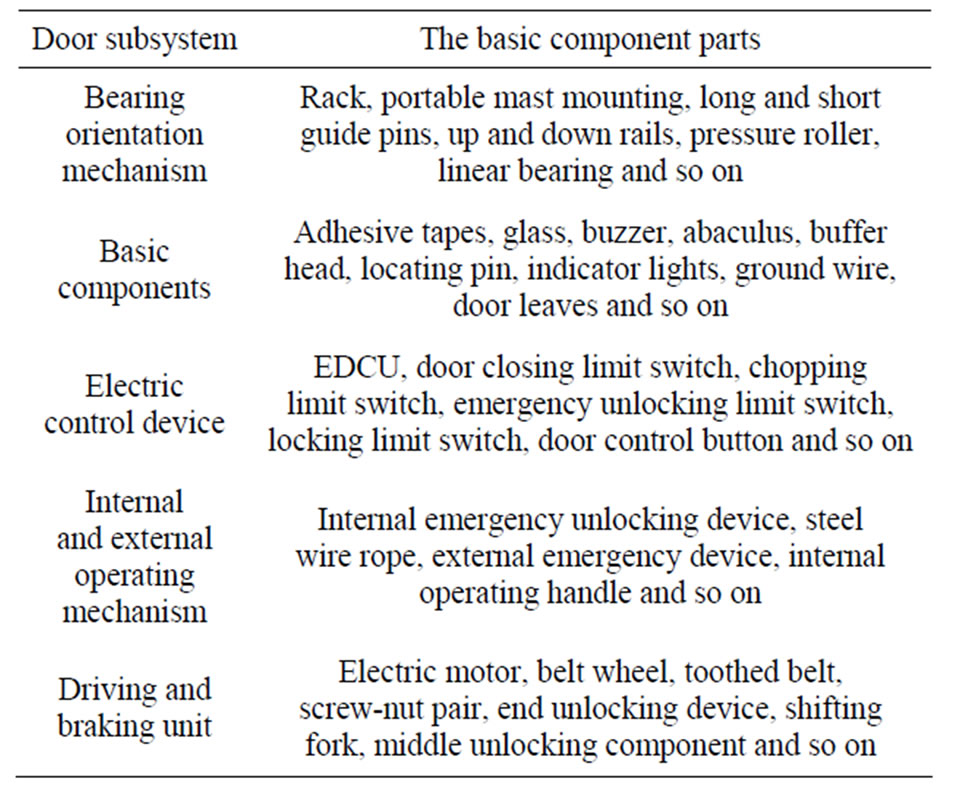
Table 1. Basic structure of door system.
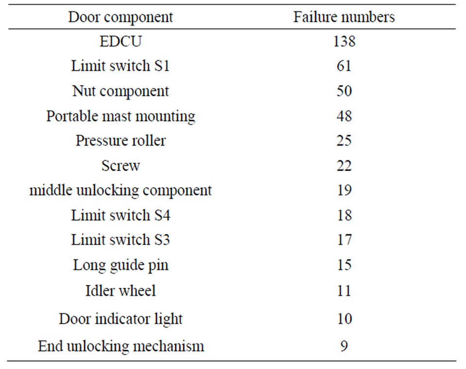
Table 2. Statistics of door failure components.
failure numbers of pressure roller, drive screw, door locking limit switch S4, emergency unlocking limit switch S3, middle unlocking component, long guide pin, idler roller, door indicator light and end unlocking device are a little low, but they still occupy approximately onethird of the total failures number, so the maintenance department should pay enough attention to them.
4. FMECA on Door System
4.1. Door System Failure Classification
Failure level stands for the severity of the consequences of failure mode on system. The failure level should be determined firstly, and then the criticality of every failure mode can be ultimately determined by using the criticality matrix diagram. In this paper, the failure level of every failure mode is divided into five categories according to the actual situation [7], as shown in Table 3.
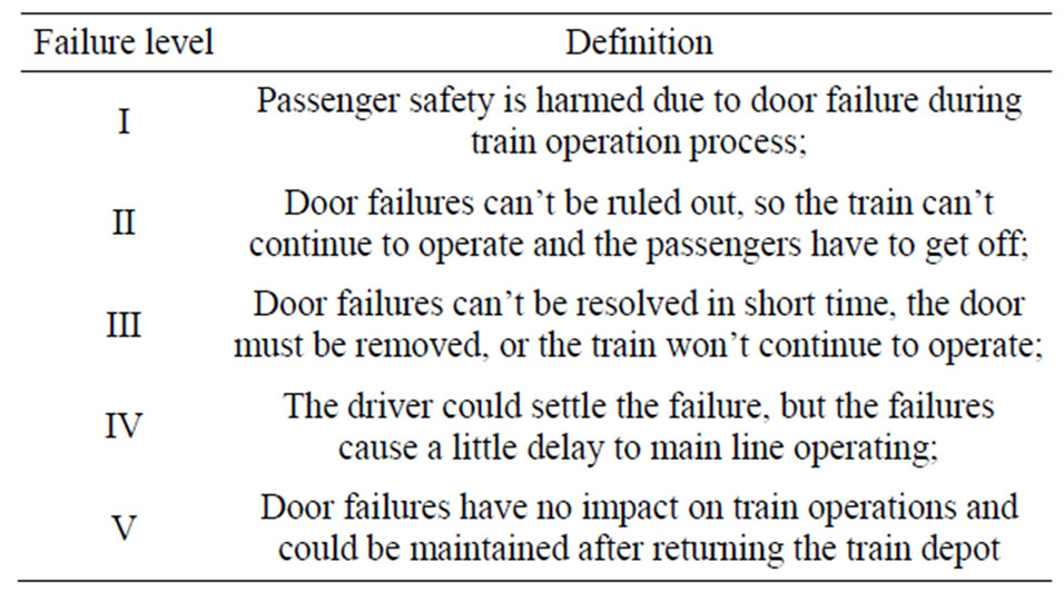
Table 3. Failure level classification.
4.2. Calculation Method of Failure Mode Criticality
The component failure mode criticality Ci is used to evaluate the perniciousness of a single failure mode, and it could be calculated as follows:
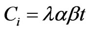
where,  is the failure rate of a component;
  is the frequency ratio of the failure mode, which means the percentage ratio of a failure mode to a component’s total failure modes;
  stands for the effect probability of a failure mode; t is the working time of a component.
Component criticality Cc is used to evaluate the perniciousness of every component and it could be calculated as follows:
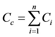
where, n is the number of failure modes for every component.
The failure rate of every component could be obtained by using the average failure rate calculation method [8], which is calculated as:
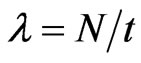
where,  is the failure rate of a component; N is the failure numbers within the specified time for a component, t is the working time of a component.
Failure effect probability  is the identified failure effect that a failure mode leads to in the conditional probability,
  is usually an estimated value. During FMECA on metro door system,
  is as follows [9]:
 , which means that the system is certainly malfunction;
 , which means that the system may malfunction;
 , which means that the system rarely fails;
 , which means that the failure mode have no effect on the system.
4.3. Ascertain the Criticality of Door Failure Mode
During reliability analysis of door system, the FMECA method is conducted on EDCU, door closing limit switch, nut component, and portable mast mounting four components which have been deemed to have a high failure rate, as shown in Table 4. Obviously, four components only cause failure level of iii, IV, V, no I and II. Failure modes of EDCU belong to failure level of III and IV, and closing limit switch S1 or nut component only cause failure level of III, and failure modes of portable mast mounting have the failure level of IV and V. When the failure level is III, the maximum and minimum criticality component is EDCU and nut component, the criticality is 125.67 and 25.53 respectively; when the failure level is IV, the maximum and minimum criticality component is EDCU and portable mast mounting, the criticality is 6.21 and 2.16 respectively; when the failure level is V, only failure modes of portable mast mounting have the failure level, the criticality is 21.8.
According to failure level and failure mode criticality in Table 4, combining with statistical analysis of failure data, the criticality matrix diagram could be obtained, as shown in Figure 1.
The Figure 1 shows the relationship between the failure levels and criticality of 12 failure modes, which is the further of failure mode distribution points along the diagonal direction from the origin, the greater of the failure mode criticality, and indicates that more attention should be paid to corresponding defective parts [10].
From the Figure 1, we can conclude apparently that the failure modes in descending order of criticality are that 2 (EDCU function failure), 3 (S1 breakage), 6 (Nut component breakage), 5 (S1 function failure), 9 (Nut component loose), 4 (S1 abnormal clearance), 7 (Nut component poor lubrication) and 8 (Nut component angle offset), 1 (EDCU plug loose), 12 (Portable mast mounting bolts loose), 11 (Portable mast mounting has crackson screws), and 10 (Portable mast mounting bushing for
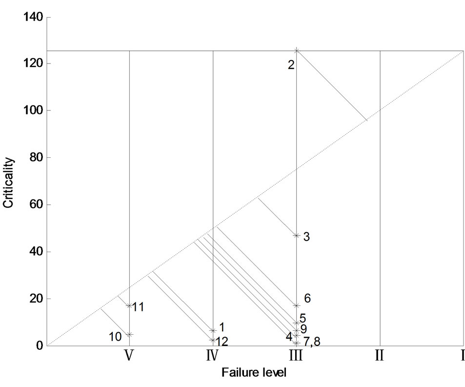
Figure 1. Criticality matrix diagram of failure modes.
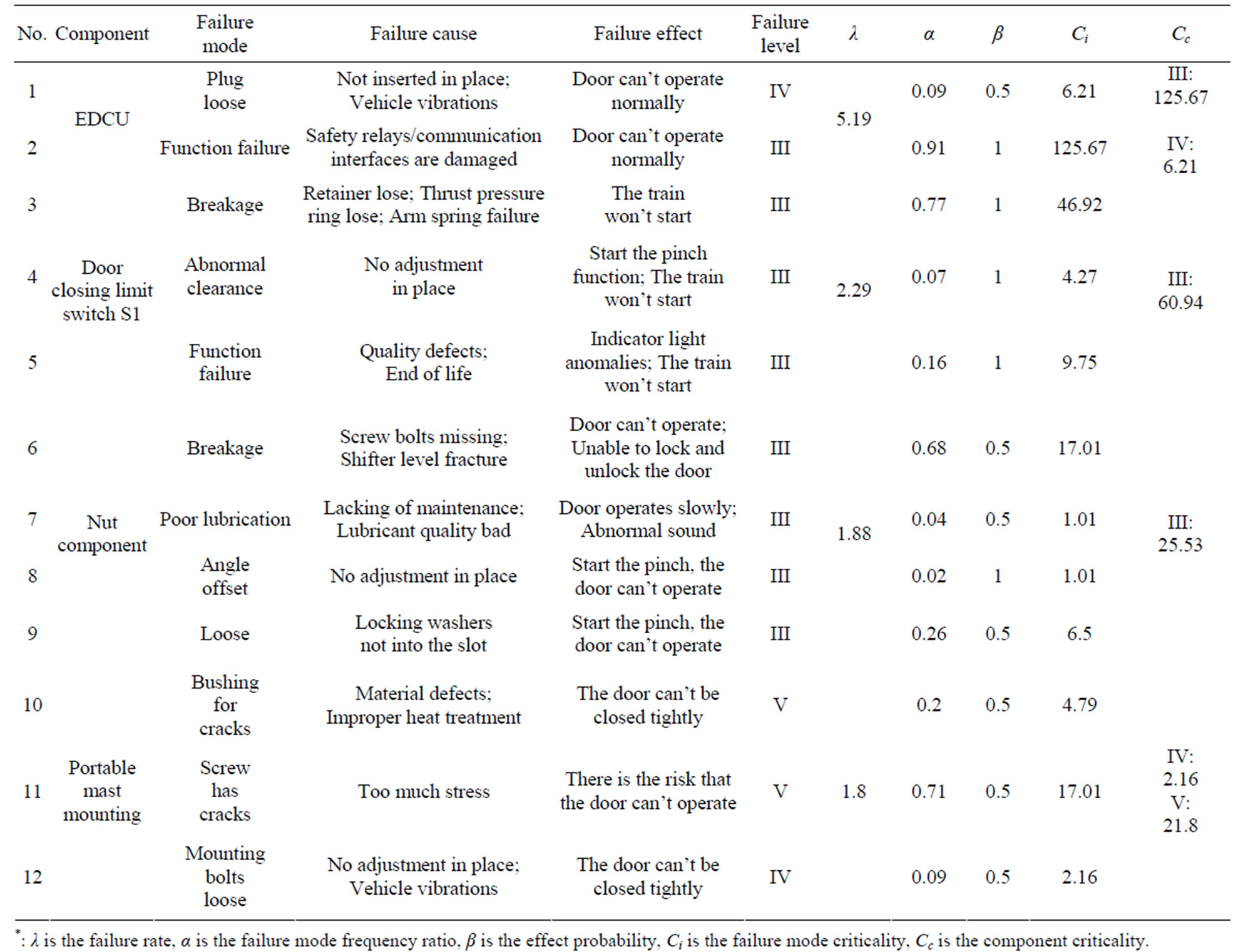
Table 4. FMECA of metro door system.
cracks). It is thus clear that the criticality of EDCU function failure and door closing limit switch S1 breakage are greater than other failure modes criticality, and they should be regarded as the key failure modes of the door system and the focus of attention in the routine maintenance. In addition, corresponding improvement measures which are combined with the actual situation should be given to door closing limit switch S1 breakage and other failure modes.
5. Conclusion
Through statistical analysis of defective components of metro door system, the FMECA method is utilized to analyze four components which have a high failure rate. The results show that the EDCU function failure and the breakage of limit switch S1 are the weakness of door system, and should be concerned in the maintenance operation. By site investigation, the results are consistent with the actual experience of field engineers. So the effectiveness of the method is verified, and the results will provide the technical support for the metro door design and maintenance decision-making.
6. Acknowledgements
The authors would like to express their thanks to the editor and anonymous reviewers for their help in revising the manuscript. This research is sponsored by National Key Technology R&D Program of China (2011 BAG01B05) and National High-Tech R&D Program of China (863 Program No. 2011AA110501).