The Application of the Ground Source and Air-to-Water Heat Pumps in Cold Climate Areas ()
1. Introduction
In cold winter areas, minimization of fuel cost for heating of buildings is a very important issue. The efficiency of wood stove heating is about 0.5. This means that it is necessary to burn 6 kWh of wood energy to produce 3 kWh of heat (thermal) energy. The efficiency of gas-boilers is about 0.85, which means it is necessary to burn 3.5 kWh of gas energy to produce 3 kWh of heat (thermal) energy. The efficiency of direct electrical heating is about 1, i.e. to produce 3 kWh of heat (thermal) energy, 3 kWh of electrical energy is needed.
Heat pumps are one of the most energy efficient equipments of heating available nowadays. Heat pumps do not produce heat; they simply move available heat from one level to another. The needed electrical energy is predominantly used to run the compressor.
If the average Coefficient of Performance (COP) of the heat pump is 3 (usually from 2.5 to 4.5), 1 kWh of electrical energy is needed to produce 3 kWh of heat (thermal) energy.
The ease of use of heat pumps is comparable to those of simple electronic household appliances: their work is completely automated and they do not require supervision. Heat pumps are suitable for heating and cooling new as well as old buildings.
In this article two types of heat pumps are treated. They can be classified as:
• devices that draw heat from the ground (with horizontal ground heat exchangers) and heat the building are called ground source heat pumps GSHP, Figure 1;
• devices that draw heat from the external air and heat the building using a water heating system are called air-to-water heat pumps A&WHP, Figure 2.
Comparing the efficiency of GSHP and A&WHP in cold climate areas it is necessary to pay attention to the following aspects:
• A&WHP should be operated at temperatures of ambient air below −20˚C or even down to −30˚C and using additional heat sources (electrical heaters) might be necessary [1];
• soil temperatures in the depth of the horizontal ground heat collector decrease to the freezing point (0˚C) in winter and the soil around the collector pipes might be frozen [2];
• a rather low floor heating water temperature regime (35/30˚C) should be used in order to achieve the best possible COP value of heat pumps [2].
Background
Different types of heat pump systems have been studied in Nordic climate conditions in order to find the most cost-optimal heat pump system. In practice, the heat pump was first introduced in 1939 in Zurich Town Hall. Heat pumps began to spread after the Second World War
(mainly reversible air-to-air heat pumps were used for cooling in summer). Ground-source heat pumps, in combination with different heat sources, have been tested with different system designs in several countries during the last 25 years. The control system has, by the microprocessor technique, opened new possibilities for operation strategies and makes it possible to design and optimize systems for different applications.
The most common type of the heat pump in Sweden today is the ground source heat pump, which extracts heat from a borehole, the ground or seawater [3]. Direct expansion systems are rare today due to negative experience from the period in the mid 1980s when they were popular. They found that the GSHP systems are typically not designed to cover the maximum heat load. They are sized to cover 55% - 60% of the requested heat power at the dimensioning outdoor temperature (DOT). Then they cover approximately 90% of the annual heat energy demand. The remaining part is covered by a supplementary heat source; typically an electric heater, but also oil burners are used.
The website of IEA Heat Pump Centre [4] includes the typical COP values of water-to-water heat pumps at different temperature graphs of the condenser if the flow temperature on the evaporator side is 5˚C. It can be concluded from these data that the higher the required temperature is produced the lower the COP of the heat pump will be. It is most useful to use the heat pump for the floor heating system. In the case of the radiator heating system the average COP is 2.5 at the temperature of 60˚C/ 50˚C and 3.5 at 43˚C/35˚C. In the case of floor heating (at 35˚C/30˚C) the COP is nearly 4.0.
ASHRAE Handbook-HVAC Systems and Equipment [5] states that the heat pump can be economical compared to other heating systems when the heating requirement of the building is covered with water temperatures of 45˚C - 50˚C. This is due to the fact that the COP of the heat pump is relatively high. In this case domestic hot water (DHW) production needs a separate solution because the temperatures of 45˚C - 50˚C are not always sufficient for producing DHW.
Abel and Voll [6] consider that the heat pump should be large enough to produce 90% of the required annual thermal energy. They also emphasise that for economic purposes it is recommended that the building should also be insulated when a heat pump is installed in an existing building. As the temperature escaping from the heat pump is lower than that from a fossil fuel boiler, already existing heaters can be used if the heat load decreases. The authors note that the low temperature of the heating system is an advantage if the heating system is based on heat pumps, because it is more efficient at low output temperatures.

Figure 1. The ground source heat pump: 1—expansion valve; 2—circulating pump; 3—evaporator; 4—condenser; 5—ground circuit; 6—heating circuit.
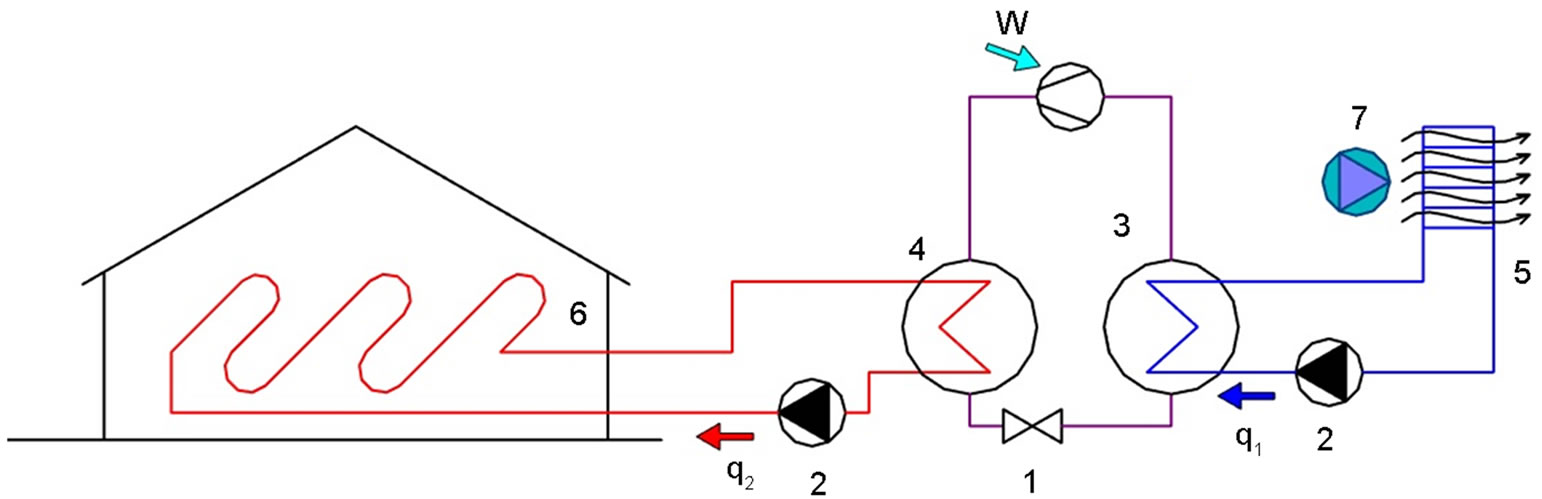
Figure 2. The air-to-water heat pump 1—expansion valve; 2—circulating pump; 3—evaporator; 4—condenser; 5—air-liquid heat exchanger; 7—ventilator.
Penjam [7] has studied heat production with GSHP for heating the building and producing DHW and has compared pollutants emitted into the atmosphere by heat pumps with other more common sources of energy. Dimensioning of heat pumps driven by electricity has been covered in Hayton’s [8] research.
Diao et al. [9] preferred using the vertical ground source heat pump because it takes less space. Also GSHP is much more stable than the air to water heat pump. However, when using GSHP, it must be noted that the borehole annulus should be protected with materials that provide thermal contact between the pipe and ground and protect groundwater from possible contamination. Because the vertical borehole penetrates several geologic strata, local specificity must be considered.
Ozgener and Hepbasli [10] tested two different systems: namely a solar assisted vertical GSHP and horizontal GSHP. Test results show that the circulator wattage for the closed loops of GSHP systems I and II can be categorized as efficient and acceptable systems, respectively.
Ground-source or geothermal heat pumps are highly efficient, renewable energy technology for space heating and cooling [11]. This technology relies on the fact that, at depth, the Earth has a relatively constant temperature, warmer than the air in winter and cooler than the air in summer. The geothermal heat pump can transfer heat stored in the Earth into a building in winter, and transfer heat out of the building in summer.
For the optimum design of the GSHP system, it is necessary to estimate its performance and economic feasibility before the introduction of the system [12]. Most analysis models are inaccurate in their predictions for long periods because they are based on a thermal conduction model using a cylindrical coordinate model or an equivalent diameter model.
Tarnawski et al. [13] conducted computer simulation and analysis of a ground source heat pump system with horizontal ground heat exchangers operating in heating and cooling. They found that in spite of the high electricity rate, the ground source heat pump system is a more beneficial alternative for space heating than the oil furnace and the electric resistance system. Besides, the heat pump technology offers relatively low thermal degradation of the ground environment, lower cost of heating and cooling, higher operating efficiency than electric resistance heating or the air-source heat pump and is environmentally clean, i.e. without greenhouse gas emission, if the electricity is generated from renewable energy resources, e.g. the wind and sun. The use of the cooling mode can provide further benefits, such as shorter investment payback and human thermal comfort in summer.
Cui et al. [14] investigated transient heat conduction around the buried spiral coils, which could be applied in the ground-coupled heat pump systems with the pile foundation as a geothermal heat exchanger. Based on the “solid” cylindrical heat source model, an improved analytical model of the ring-coil heat source is established to better illustrate the heat transfer process of PGHE with spiral coils. Coil type heat exchangers are used because the spiral coil configuration has the advantage of more heat transfer area and a better flow pattern without air chocking in the pipes compared to the serial of parallel U-tubes in the pile.
Li and Lai [15] analyzed the influence of anisotropy of anisotropic soil on the processes of heat transfer by GCHP. Several important conclusions are listed: anisotropy of media affects the heat conduction process only over longer time spans, the differences between the cylindrical surface model and spiral line model are very small. So, both can be used to analyze the heat transfer process.
Thermal response tests were carried out in a Korean laboratory [16]. The tests were made to develop an efficient spiral coil source model and its analytical solution, to consider the 3-dimensional shape effects and radial dimension effects of the spiral coil type ground heat exchanger (GHE) using Green’s function method. The results of the analytical solution of the spiral coil source model are in good agreement with the overall behavior.
Energy performance of A&WHP and GSHP are studied in the current paper.
2. Method
The ideal heat pump works according to the reversed Carnot’ thermodynamic cycle (see Figure 3) and its Coefficient of Performance (COPC) is simply expressed by absolute temperatures
 (1)
(1)
where
T1—the condensing temperature of the refrigerant, K;
T2—the evaporation temperature of the refrigerant, K.
The working process of a real steam compressor heat pump might be described in a ph-diagram shown in Figure 4. It differs significantly from the ideal, i.e. from the reversed Carnot cycle. The real heat pump cycle looks like a reversed Rankine cycle equipped in addition with an expansion valve. In the valve (line 1 - 2) the pressure of the saturated liquid working fluid abruptly decreases causing auto-refrigeration and flash evaporation of part of the liquid. In the evaporator (line 2 - 3) the cold mixture of liquid and vapor receives heat q1 from the low temperature heat source and completely vaporizes. In the compressor (line 3 - 4) the pressure increases and the working fluid converts into superheated vapor. In the condenser the superheated vapor is at first cooled and

Figure 3. The reversed Carnot’ cycle in a Ts-diagram.

Figure 4. The working process of a real steam compressor heat pump with heat regeneration in a ph-diagram.
afterwards converted into liquid (line 4 - 4’ - 1). In the condenser heat q2 is relieved and might be used for space heating.
Heat pump systems for space heating consume energy not only for driving the compressor but also for other purposes in the system, incl. driving pumps and/or fans and for compensation of heat losses.
The relative efficiency of a real heat pump heating system might be expressed as
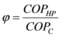 (2)
(2)
where COPHP—the COP value of the heat pump heating system
φ—the relative efficiency of the real heat pump heating system.
In the case of small-scale heat pumps for heating a detached house, the value of φ might be about 0.5, and in the case of advanced powerful heat pumps for district heating up to 0.7.
In cold climate areas the temperatures of energy sources (soil and ambient air) vary to a large extent during a year (see Figures 5 and 6) and annual (seasonal) electricity consumption and the Coefficient of Performance (COPHP) should be calculated by simulating the heating process of a building).

Figure 5. Ambient air temperatures in Estonia (Tallinn, 59˚ north latitude) during 1993-2012.
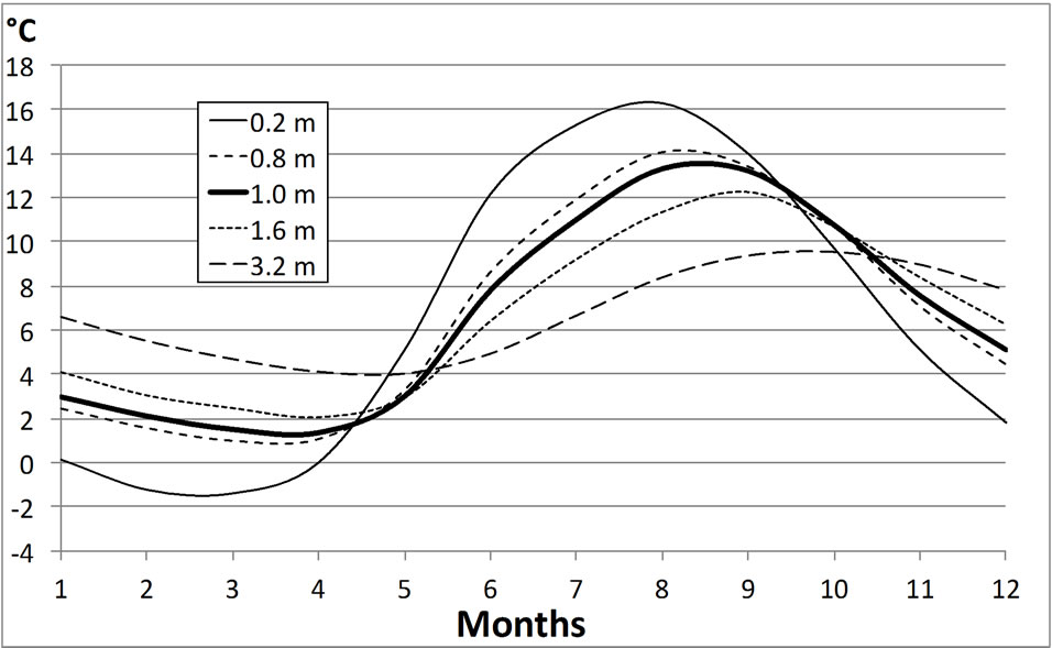
Figure 6. Average soil temperatures in Estonia at the depths of 0.2 - 3.2 m.
Simulation of the heating process allows taking into account the real changes in conditions during the year, such as
• ambient air temperature profile during a year in case of A&WHP and energy demand for defrost process of the surfaces of evaporation heat exchanger;
• soil temperature profile during a year in the depth of ground heat collector (1 m in this study) in case of GSHP;
• design and temperature regime of the water heating system of a building;
• hot tap water demand;
• technical parameters of the heat pump.
Long term measurements (about 30 years) at the depths of 0.2, 0.8, 1.6 and 3.2 m have been performed by the Institute of Geology of the Estonian Academy of Sciences. Temperatures at the depth of 1.0 m have been calculated.
3. Results
The existing building stock in European countries accounts for over 40% of the final energy consumption in the European Union (EU) member states, of which residential use represents 63% of the total energy consumption in the building sector. Improving energy performance in the building sector is therefore a key factor to achieve the EU’s climate and energy objectives for 2020, including the reduction of CO2 emissions and 20% energy saving [17]. Therefore it is very important to evaluate the factors that would increase energy consumption already during the design process. In addition, the European energy performance directive for buildings (Energy Performance Building Directive-EPBD) states that the energy efficiency of buildings has to be calculated in the member states [18].
Description of the Building
The object of modeling is a 2-storey detached house (see standard floor Figure 7), which is situated in Tallinn. The height of floors is 3.0 m and the height of rooms is 2.7 m. The temperature of indoor air is assured by floor heating with water parameters 35/30 and the ventilation air is heated with the water based battery.
To avoid the impact of the usage of the building, the calculations are made with standard usage and by unified calculation methodology. The methodology is specified in local regulations [19]. According to the methodology, the ventilation air flow is 0.42 l/(s·m2) and the demand for domestic hot water (DHW) heating is 45 l/(pers.*day). The house has no mechanical cooling system. The building has also a mechanical supply and exhaust ventilation system with heat recovery (the efficiency of heat recovery is 0.75; the specific fan power is 2.5 kW/(m3·s); the minimal achievable leaving air temperature is 5˚C; the temperature of the supply air to the rooms is +18˚C). The living area of the building is 200 m2.
The thermal transmittances of the envelope are shown in following table (see Table 1). Pilkington Optitherm S4 type of windows are used, made of triple glass and filled with argon. The thermal transmittance of the frame is 1.4 W/(m2·K) and the area of the frame is 15% of the whole window. The maximum heat loss of the building is 9 kW.
The model has been made exactly according to the architectural plan of the building. The CAD-file of the building was imported to the program, which guarantees sufficiently exact accomplishment of the model. The plans and views of the building are shown in Figures 7 and 8.
The model of the building has been made using IDA indoor Climate and Energy 4.5 (IDA-ICE) building simulation software [20]. IDA Indoor Climate and Energy (IDA ICE) is a tool for simulating the energy consumption, indoor air quality and thermal comfort of a building. It covers a large range of phenomena, such as the integrated airflow network and thermal models, CO2 and moisture calculation, and vertical temperature gradients.
For example, wind and buoyancy driven airflows through leaks and openings are taken into account via a fully integrated airflow network model. The model has been made exactly according to the architectural plan of the building. The CAD-file of the building was imported to the program, which guarantees sufficiently exact accomplishment of the model [21].
The current study investigates mainly the influence of different heat pump systems on energy performance. The main investigated systems are the ground source heat pump and the air to water heat pump. The results of the simulations of the air to water heat pump are shown in
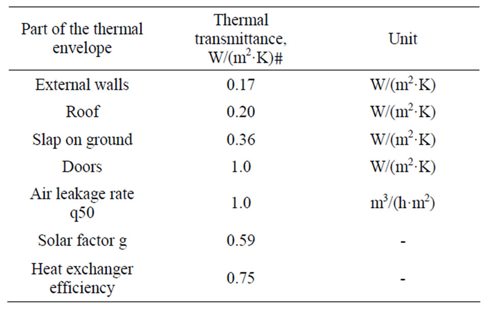
Table 1. Initial data of the building model.
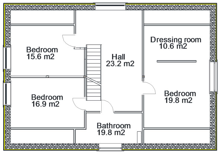

Figure 7. The ground (left) and first (right) floor of the building.
Figures 9-11. The mean loads and energy consumption of the air-to-water heat pump system are included in Table 2.
As shown in Table 2 the annual heat production of the air to water heat pump for heating and ventilation is 16911 kWh, for DHW is 4251 kWh and the mean COP is 2.6. The average COP value of the summer period (May to September) is 2.5 and average COP value of heating period (October to April) is 2.7. In summer period the heat pump produces mainly DHW. The low average COP value of summer period can be explained as the fact that DHW has to be heated to 55˚C. At the same time in case of floor heating system the lower parameters (35˚C/30˚C) are used.
The results of the simulations of the ground source heat pump are shown in Figures 12 and 13. The mean loads and energy consumption of the ground source heat pump system are included in Table 3.
According to Table 3, the annual heat production of the ground source heat pump for heating and ventilation is 17179 kWh, for DHW is 4256 kWh and the mean COP is 2.9. The average COP value of air to water heat pump of the summer period (May to September) is 2.6 and average COP value of heating period (October to April) is 3.2. In heating period the average COP of the air to water
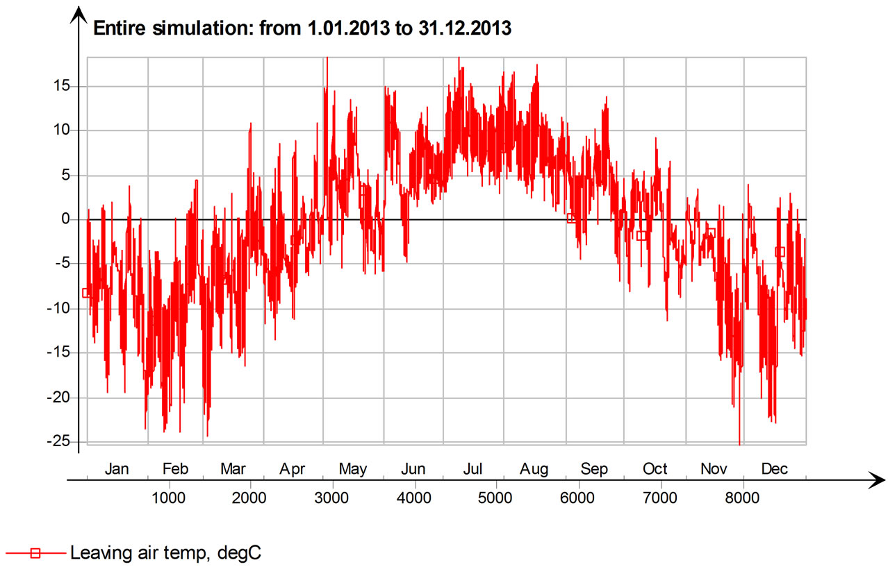
Figure 9. The temperature of the air leaving from the evaporator of the A&WHP.
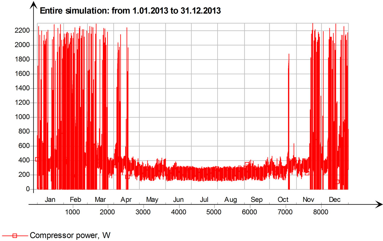
Figure 11. The power of the compressor of A&WHP.
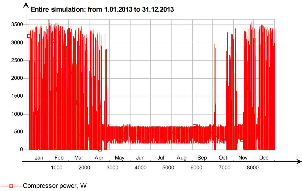
Figure 13. Compressor power of the GSHP.

Table 2. The seasonal energy consumption, COP and mean load of the air-to-water heat pump system.
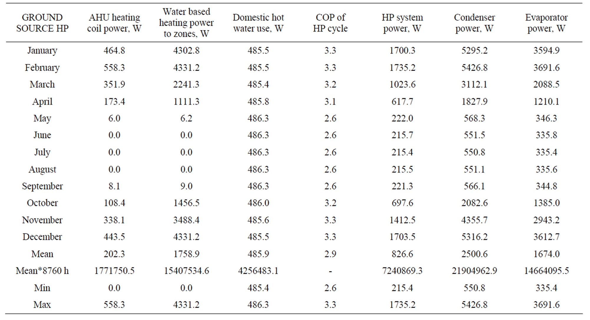
Table 3. The seasonal energy consumption, COP and mean load of the ground source heat pump system.
heat pump is considerably lower than COP of the ground source heat pump.
4. Conclusions
This article gives an overview of using the ground source heat pump (GSHP) and air-to-water heat pump (A&WHP) in cold climate areas for heating and for domestic hot water production of buildings. Computer simulation and analysis were carried out for a typical 2-storey detached house, with 200 m2 of living area, the heat demand of 9 kW and the average heat demand for DHW production of 1 kW. The model of the building has been made using IDA indoor Climate and Energy 4.5 (IDA-ICE) building simulation software.
The annual heat production of the air to water heat pump for heating and ventilation is 16,911 kWh, for DHW is 4251 kWh and the mean COP is 2.6. The annual heat production of the ground source heat pump for heating and ventilation is 17,179 kWh, for DHW is 4256 kWh and the mean COP is 2.9. The average COP of the air to water heat pump is 2.5 in summer period and 2.7 in heating period. The average COP of the ground source heat pump is 2.6 in summer period and 3.2 in heating period.
5. Acknowledgements
The research was supported by the Estonian Research Council, with Institutional research funding grant IUT1- 15, and with the project “Development of efficient technologies for air change and ventilation necessary for the increase of energy efficiency of buildings, AR12045”, financed by SA Archimedes and by the project “Civil and Environmental Engineering PhD School, DAR9085”.
NOTES