Natural Resources
Vol. 4 No. 1 (2013) , Article ID: 29172 , 7 pages DOI:10.4236/nr.2013.41008
Performance Evaluation of Single Bed Desiccant Desorption Process
![]()
1Mechanical Power Engineering Department, Faculty of Engineering, Tanta University, Tanta, Egypt; 2Mechanical Power Department, Faculty of Engineering, Mansoura University, Mansoura, Egypt; 3Mechanical Engineering Department, Faculty of Engineering, Taif University, Taif, KSA.
Email: samadony25@yahoo.co.uk, amhamed1@yahoo.com, kabeel6@hotmail.com
Received December 8th, 2012; revised January 12th, 2013; accepted January 24th, 2013
Keywords: Desiccant; Regeneration; Desorption; Silica Gel
ABSTRACT
In the present study, dynamic performance of single bed desiccant regeneration system has been investigated experimentally. The desiccant bed operates as an adsorber and then as a regenerator, intermittently. In the experimental work of this investigation, Silica gel is used as a desiccant material. In the regeneration process, hot air from an air heater is blown through the bed using an air blower. The performance of desorption process at different conditions of flowing air is demonstrated. The experimental tests were carried out at different conditions of inlet air and initial bed parameters. Temperature and humidity of air at inlet and exit of the bed were measured. The obtained results showed that hot air with an inlet temperature ranging from 40˚C to 75˚C could release a notable amount of water from the desiccant bed. The relation between the studied parameters during the desorption processes is correlated. Results also show that the “Rehabilitation period” in desorption process should be eliminated to decrease the desorption time and it could be eliminated if the hot air mass flow rate is greater than 1.92 kg/hr per kg of silica gel.
1. Introduction
Refrigeration and air conditioning systems consume a large amount of electric energy especially in hot humid areas. It is a wise decision to use all scientific means to reduce the energy consumed in air conditioning systems. Desiccants are substances known for their ability to absorb water vapour. Therefore, they can be used effectively not only to overcome the latent cooling load of air conditioning systems and improve the indoor quality but also to dehumidify air for any industrial applications. Poor indoor air humidity condition can affect the incidence of respiratory infections and allergies, disrupt the body’s ability to cool itself, be susceptible to diseases like flu, and thrive dust mites. Description and operation of desiccant air conditioning systems can be found in several investigations [1-5].
In order to have a continuous operation whereby a desiccant removes water vapour from air, the desiccant must be regenerated continuously. Regeneration (desorption) of a desiccant is usually achieved by heating. The heat required for regenerating the weak desiccants can be supplied by fossil fuel, waste heat, or any form of lowgrade thermal energy, and most of the time, solar energy is used in such processes. Several studies have been conducted on the operation of the desiccant dehumidification/regeneration employing evaporative cooling processes [6-9].
Theoretical and experimental study on the desorption characteristics of vertical packed porous bed was carried out by Hamed [10]. He investigated a theoretical model to describe the effect of independent parameters (time, and vertical distance) on the vertical gradient of desorbable fluid in a desiccant bed.
Hamed et al. [11] studied experimentally the transient adsorption/desorption characteristics of solid desiccant in a vertical fluidized bed. They found that, the relation between the desorbed water and the moisture fraction for material depends on the thermo-physical properties of the solid desorbate-desorbent pair. The maximum value of air exit humidity during desorption (regeneration) is dependent on the regeneration temperature. Also, they found that, vapour generation rate increases gradually with the increase in bed temperature and consequently the mass transfer potential.
Kabeel [12] studied the effect of design and operating parameters on the performance of a multilayer desiccant packed bed theoretically and experimentally. He compared his experimental and theoretical results with that of Abd-Elrahman [13], and the results showed reasonable agreement.
Awad et al. [14] investigated theoretically and experimentally adsorption/desorption operations of a hollow cylindrical packed bed. They found that the pressure drop in hollow cylindrical bed was too small compared with that in the vertical packed bed. They found also that a transient period “start-up period” from adsorption to desorption is needed and this start-up period will be decreased in case of cyclic operation. Theoretical investigation of the cyclic operation of the radial flow solid desiccant dehumidifier has been reported [15]. A mathematical model has been developed to predict the effect of air inlet conditions (humidity, temperature and flow rate) as well as bed design parameters on the desiccant bed dynamic performance during cyclic operation. The results show that, lower values of the humidity of process air at bed exit could be attained with increase in regeneration temperature [15].
EL-Samadony et al. [16] divided adsorption time of single desiccant bed into four stages and studied the effect of the operating parameters on the global adsorption performance and the divided stages’ periods.
In the present study, an experimental unit has been designed and installed to evaluate the effect of design and operating parameters on the dynamic performance of the experimental unit. Several objectives are formulated to address the overall goal of the present study; evaluation of the effect of design and operating parameters on the performance of single bed desiccant dehumidification system. These objectives are to:
1) Design and installation of a single vertical bed desiccant system coupled with an air heater for regeneration of silica gel in the bed.
2) Study and discuss the operation of the proposed system and evaluate the possibility of steady state operation.
2. Description of the Single Bed Adsorption-Desorption System
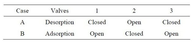
The experimental unit has been designed and installed to evaluate the effect of design and operating parameters on the performance of the experimental unit. A schematic diagram of the single bed adsorption-desorption air dehumidification system is illustrated in Figure 1. The system consists of one desiccant bed and three control valves. Silica gel (95% White + 5% blue, with an average diameter of 3.5 mm) is used as desiccant. Bed dimensions are 21 cm diameter and 90 cm height. The operation schedule of control valves is given in Table 1.
3. Experimental Work
The adsorption and desorption processes were studied for a single bed at different conditions such as air mass flow rate, hot air regeneration temperature and humidity ratio. The system consists of different parts. The blower is used to blow the atmospheric air in the bed. The heater is used to regenerate the desiccant, silica gel, by heating the air. A variac (transformer) is used to change the regeneration air temperature by changing the supplied volt. The air flow rate to the system is controlled by the valves (see Figures 1(b) and (c)) and measured by means of a anemometer. Two valves are used to control the air flow rate, valve 1 for adsorption and valve 2 for desorption process. Air inlet and outlet conditions (dry bulb temperature and relative humidity) were measured and recorded by means
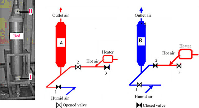
Figure 1. Single bed adsorption-desorption air dehumidification system. (a) View of the experimental unit; (b) Desorption mode; (c) Adsorption mode.
Table 1. The operation schedule of control valves.
of a data logger every 10 seconds. The measuring points of air are just before and after Silica gel’s bed, as shown in Figure 1(a) at points I and II. The humidity ratio of air was calculated by knowing its dry bulb temperature and relative humidity [17].
The switching between case (a) and case (b) (as shown in Figure 1) is carried out when the air humidity ratio at outlet is close to that at inlet. At this situation, desiccant bed does not has any ability to adsorb or desorp water vapour. To reduce the amount of heat lost from the desiccant bed during the regeneration process, the bed was covered by an insulation layer.
4. Results and Discussion
The performance of desiccant packed bed during regeneration processes was evaluated by conducting a series of runs with different inlet conditions of air stream, listed in Table 2. This study included the effect of the hot air regeneration temperature and air mass flow rate on regeneration time.
4.1. Regeneration Process
Figures 2-5 illustrate the variation of the outlet to inlet air humidity ratio with the regeneration time for a different air mass flow rates and inlet hot air regeneration temperature. It can be seen from these Figures that the graphical relationships between outlet to inlet air humidity ratio and desorption time seemed to be looks like “n” curve i.e. the outlet to inlet air humidity ratio firstly increases and then decreases with time. In the present study, the desorption process will be divided into four periods; namely “Rehabilitation period”, ascending period, uppermost period and descending period, as shown in Figure 6.
During the “Rehabilitation period”, the ratio of the outlet to inlet air humidity ratio is less than one. Consequently, an opposite process, adsorption, will be occurred. This is because; at the beginning of the regeneration process Silica gel temperature was lower than that for the inlet hot air. Consequently, Silica gel vapour pressure was lower than that for the inlet hot air. As soon as Silica gel is heated up, the value of mass transfer driving forces will be changed. Consequently, the mass transfer direction between Silica gel and inlet air will be changed from adsorption to desorption process. In the second period, ascending period, the rate of desorption increases with time. The uppermost period is the period at which the
Table 2. Air inlet conditions.


Figure 2. Regeneration process at T4 and Q4.
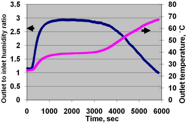
Figure 3. Regeneration process at T4 and Q3.
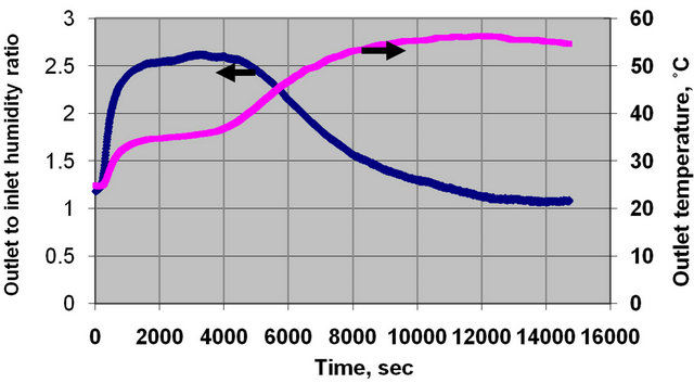
Figure 4. Regeneration process at T3 and Q3.
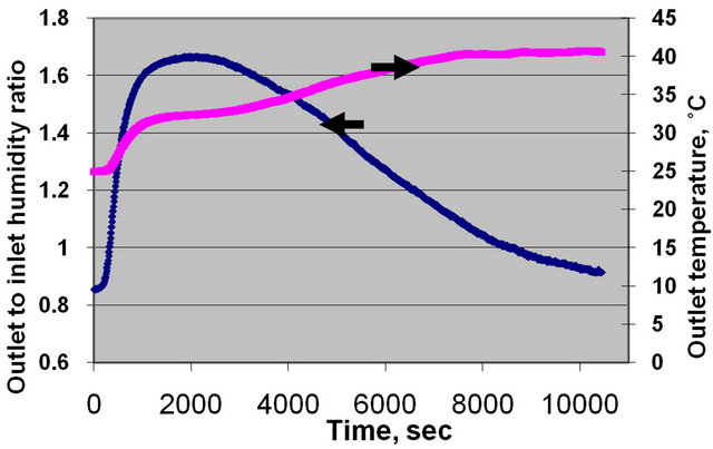
Figure 5. Regeneration process at T2 and Q3.

Figure 6. Regeneration process parts, at T2 and Q2.
rate of desorption is reached to its maximum value for a given conditions. Finally, the forth period, the descending period, the rate of desorption decreases with time. It could be seen from Figures 2-5 that the value of each previous period is varied with the regeneration temperature and air mass flow rate. The value of “Rehabilitation period” may be tends to zero for high regeneration temperature and air mass flow rate.
It can be seen also from Figures 2-5 that the outlet air temperature increases as regeneration time increases. This is because as regeneration time increases desorption rate decreases, and thus less desorption heat consumption.
4.2. Effect of Hot Air Mass Flow Rate
Figures 7-10 illustrate the variation of the outlet to inlet air humidity ratio with the regeneration time for different hot air mass flow rates and at different regeneration temperatures. It can be seen from these Figures that the ascending desorption rate period decreases as the amount of air mass flow rate increases. This is because as amount of air mass flow rate increases, air heat capacity increases and hence could reach to the uppermost period in a short time. Also, it can be seen, from these Figures that the “Rehabilitation period” decreases as the amount of air mass flow rate increases. This is because as the amount of air mass flow rate increases air heat capacity increases and hence could increase Silica gel temperature in a shorter period. It could be concluded that “Rehabilitation period” can be eliminated if hot air mass flow rate is greater than 1.92 kg/hr per kg of silica gel. Finally, it could be seen from these figures that, as amount of air mass flow rate increases desorption time decreases.
4.3. Effect of Regeneration Temperature
Figures 11-14 illustrate the variation of the outlet air humidity ratio with desorption time for different hot air regeneration temperature and at a different air mass flow rate. It can be seen from these figures that as hot air regeneration temperature increases outlet to inlet air humidity
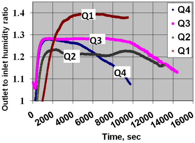
Figure 7. Variation of outlet to inlet humidity with time for different values of flow rate at T1.

Figure 8. Variation of outlet to inlet humidity with time for different values of flow rate at T2.

Figure 9. Variation of outlet to inlet humidity with time for different values of flow rate at T3.

Figure 10. Variation of outlet to inlet humidity with time for different values of flow rate at T4.
ratio increases. The value of the outlet to inlet air humidity ratio could reach 1.20 and 3.0 for air regeneration temperature of 40˚C and 75˚C, respectively. Consequently,

Figure 11. Variation of outlet to inlet humidity with time for different values of regeneration temperature at Q1.

Figure 12. Variation of outlet to inlet humidity with time for different values of regeneration temperature at Q2.

Figure 13. Variation of outlet to inlet humidity with time for different values of regeneration temperature at Q3.
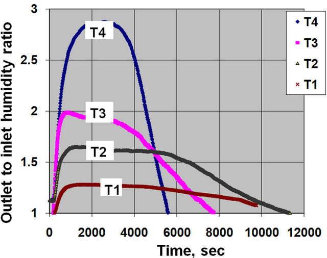
Figure 14. Variation of outlet to inlet humidity with time for different values of regeneration temperature at Q4.
the amount of released water vapour is increased. Hence, better adsorption process will be expected in the following adsorption process. Also, it could be seen that, as the regeneration temperature increases desorption time decreases. This is because the value of the mass transfer driving force increases as temperature increases. This cause high regeneration rate and hence leads to low regeneration time. It could be seen that the value of desorption time for low regeneration temperature is nearly double or less than that for high regeneration temperature. Finally, it can be seen, from these figures that the “Rehabilitation period” increases as the regeneration temperature decreases especially at low air mass flow rates.
4.4. Experimental Uncertainty Analysis
In the present section, the uncertainty analysis of the experimental results is obtained according to [18]. The measurements are done to obtain the following results; air humidity ratio, w, and adsorption/desorption capacity percentage. These results are functioned of two independent variables; dry bulb temperature, t, and relative humidity, j, thus
 (1)
(1)
Let ww be the uncertainty in the result and Wt and Wj, be the uncertainties in the independent variables. The uncertainty in result is calculated according to the equation proposed by [12] as follows:
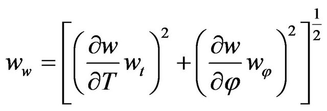 (2)
(2)
where wt: Uncertainty associated with the measuring dry bulb temperature’s = ±0.3˚C;
wf: Uncertainty associated with the measuring relative humidity = ±5 RH%. Calculations show that uncertainties in calculating air humidity ratio and adsorption capacity percentage are 0.33% and 0.23% respectively.
4.5. Experimental Correlation of Air Desorption Processes
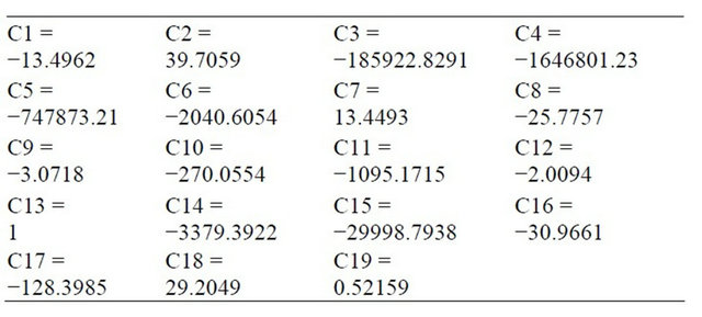
The Experimental results (about 16,376 data points) are used to obtain a mathematical correlation of outlet to inlet air humidity ratio as a function of time, air mass flow rate and air regeneration temperatures, represented by Equation (3). Hopefully, the average error between the actual value, experimental calculated value, of the outlet to inlet air humidity ratio to that obtain from the present correlation is 0.24. The average error is calculated by calculating the absolute error between the actual experimental value of each outlet to inlet air humidity ratio data and the value that may obtained from the correlation. The average error is the average value of all absolute errors of each data point.
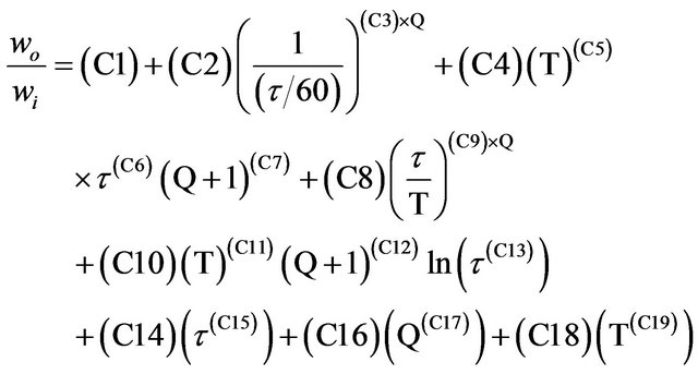 (3)
(3)
where 0.00967 £ Q £ 0.012870, 40 £ T £ 75, 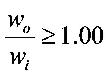
5. Conclusions
Desiccant dehumidification system of single bed has been designed, built and tested. Transient desorption characteristics of silica packed bed has been studied. Experimental results of the instantaneous variation of the air exit parameters (humidity and temperature) are demonstrated. The measurements obtained from the specific tests carried out on desiccant humidification system using silica gel as the working desiccant have been analyzed and highlighted. From the analysis, the following conclusions can be drawn.
1) Inlet air temperature in the regeneration process has a great influence on the regeneration process. As the regeneration performance at high temperature could 2.5 times that at low regeneration temperature. Also, results show that the “Rehabilitation period” in desorption process should be eliminated to avoid an opposite process and to decrease desorption time.
2) “Rehabilitation period” is mainly depends on hot air mass flow rate and it can be eliminated if the hot air mass flow rate is greater than 1.92 kg/hr per kg of silica gel.
3) Desorption time decreases by increasing air mass flow rate and inlet air regeneration temperature.
4) An acceptable correlation of outlet to inlet air humidity ratio in a desorption process is obtained with an average error of 0.24.
REFERENCES
- S. Farooq and D. M. Ruthven, “Numerical Simulation of a Desiccant Bed for Solar Air Conditioning Applications,” Transaction of the ASME, Vol. 113, 1991, pp. 80-88.
- T. S. Kang and I. L. Maclaine-Cross, “High Performance, Solid Desiccant, Open Cooling Cycles,” Journal of Solar Energy Engineering, Vol. 111, No. 2, 1989, pp. 176-183.
- M. Epstien, M. Grotmes, K. Davidson and D. Kosar, “Desiccant Cooling System Performance: A Simple Approach,” Journal of Solar Energy Engineering, Vol. 107, No. 1, 1985, pp. 21-28. doi:10.1115/1.3267648
- M. Dupont, B. Celestine and B. Beghin, “Desiccant Solar Air Conditioning in Tropical Climates: II—Field Testing in Guadeloupe,” Solar Energy, Vol. 52, No. 6, 1994, pp. 519-524. doi:10.1016/0038-092X(94)90659-9
- I. Pentchev, K. Paev and I. Seikova, “Dynamics of NonIsothermal Adsorption of Packed Bed of Biporous Zeolites,” Chemical Engineering, Vol. 85, No. 2-3, 2002, pp. 245-257. doi:10.1016/S1385-8947(01)00160-7
- W. Pridasawas, “Solar-Driven Refrigeration Systems with Focus on the Ejector Cycle,” Doctoral Thesis, Stockholm, 2006.
- D. G. Waugaman, A. Kini and C. F. Kettleborough, “A Review of Desiccant Cooling Systems,” Journal of Energy Resources Technology, Vol. 115, No. 1, 1993, pp. 1- 8. doi:10.1115/1.2905965
- P. Mazzei, F. Minichiello and D. Palma, “HVAC Dehumidification Systems for Thermal Comfort: A Critical Review,” Applied Thermal Engineering, Vol. 25, No. 5-6, 2005, pp. 677-707. doi:10.1016/j.applthermaleng.2004.07.014
- K. Daou, R. Wang and Z. Xia, “Desiccant Cooling Air Conditioning: A Review,” Renewable and Sustainable Energy Reviews, Vol. 10, No. 2, 2006, pp. 55-77. doi:10.1016/j.rser.2004.09.010
- A. M. Hamed, “Desorption Characteristics of Desiccant Bed for Solar Dehumidification/Humidification Air Conditioning Systems,” Renewable Energy, Vol. 28, No. 13, 2003, pp. 2099-2111. doi:10.1016/S0960-1481(03)00075-2
- A. M. Hamed, W. R. Abd-elrahman and S. H. El-Emam, “Experimental Study of the Transient Adsorption/Desorption Characteristics of Silica Gel Particles in Fluidized Bed,” Energy, Vol. 35, No. 6, 2010, pp. 2468-2483. doi:10.1016/j.energy.2010.02.042
- A. E. Kabeel, “Adsorption-Desorption Operations of Multilayer Desiccant Packed Bed for Dehumidification Applications,” Renewable Energy, Vol. 34, No. 1, 2009, pp. 255-265. doi:10.1016/j.renene.2008.04.011
- W. R. Abd-Elrahman, “Theoretical and Experimental Study on the Performance of a Fluidized Air Dryer,” M.Sc. Thesis, Mansoura University, Mansoura, 2005.
- M. M. Awad, A. K. Ramzy, A. M. Hamed and M. M. Bekheit, “Theoretical and Experimental Investigation on the Radial Flow Desiccant Dehumidification Bed,” Applied Thermal Engineering, Vol. 28, No. 1, 2008, pp. 75- 85. doi:10.1016/j.applthermaleng.2006.12.018
- A. K. Ramzy, A. M. Hamed, M. M. Awad and M. M. Bekheit, “Theoretical Investigation on the Cyclic Operation of Radial Flow Desiccant Bed Dehumidifier,” Journal of Engineering and Technology Research, Vol. 2, No. 6, 2010, pp. 96-110.
- Y. El-Samadony, A. M. Hamed and A. E. Kabeel, “Dynamic Performance Evaluation of Single Bed Desiccant Dehumidification System,” International Journal of Renewable and Sustainable Energy, Vol. 2, No. 1, 2013, pp. 18-25.
- “ASHRAE Handbook-Applications,” American Society of Heating, Ventilation and Air Conditioning Engineer, Atlanta, 1997.
- J. P. Holman, “Experimental Method for Engineers,” 6th Edition, McGraw-Hill, Singapore City, 1994.
Nomenclatures
Q: Air mass flow rate, kg/s;
tdb: Air dry bulb temperature, ˚C;
T: Inlet hot air regeneration temperature, ˚C;
w: Air humidity ratio, g/kg;
wt: Uncertainty associated with measuring dry bulb temperature, ˚C;
wj: Uncertainty associated with measuring relative humidity, %;
ww: Uncertainty associated with calculating humidity ratio, %.
Greek Symbols
j: Air relative humidity, %;
t: Time, sec.
Subscripts
1: Inlet condition number 1;
2: Inlet condition number 2;
3: Inlet condition number 3;
4: Inlet condition number 4;
i: Inlet;
o: Outlet.