World Journal of Nano Science and Engineering, 2011, 1, 73-78
doi:10.4236/wjnse.2011.13011 Published Online September 2011 (http://www.SciRP.org/journal/wjnse)
Copyright © 2011 SciRes. WJNSE
Analysis of Cr Atoms Three-Dimensional
Deposition Characteristics*
Hua-Lei Yang, Wen-Tao Zhang, Jian Yang
Department of Electrical Engineering and Automation, Guilin University of Electronic Technology, Guilin, China
E-mail: mnvad@163.com
Received July 23, 2011; revised August 9, 2011; accepted August 16, 2011
Abstract
The semi-classical model is used to simulate the three-dimensional trajectory and deposition distribution of
the chromium atoms in the Gaussian laser standing wave field using the Runge-Kutta method, and then the
three-dimensional deposition stripes are also given, besides, the effects of atomic beam divergence, chro-
matic aberration and spherical aberration on deposition structure are also analyzed.
Keywords: Three-Dimensional Analysis, Atom Deposition, Cr Atoms, Gaussian Laser Standing Wave Field
1. Introduction
Nanotechnology is one of the fastest growing, most ex-
tensively studied, and putting up the most in the territory
of science and technology currently, and it is known as
the 21st-century science. Its purpose is to “research, develop
and process those materials, devices and systems whose
construction sizes are smaller than 100 nanometers in
order to obtain the required functionality and perfor-
mance [1]”. This definition covers the process of nano-
fabrication, designs, characteristics and shapes of nano-
structures, and measurement and characterization methods
of nano-scale.
Nanometer measurement plays an irreplaceable im-
portant role in information collection and analysis of the
nanotechnology. Nanometrology is involved with the in-
tervals and displacements of the measurement objects
within the range of 0.1 nm - 100 nm, the features of ob-
jects and their surface morphology, the development of
technology and instrument of nano-micro-electronics,
micro-machinery and precision measurement, the re-
search on the interaction of probe and measured surface
during nano-measurement as well as structures and in-
tervention calibration methods of nano-devices. In order
to achieve the calibration of nano-test-equipments in
working sites or general laboratories, a good nano-scale
length transfer standard is needed.
Therefore, to develop accurate and applicable nano-
transfer standard is the present urgent problem and re-
search priorities. Its technical routes are mainly along
three directions, and one of it is laser focused atomic
deposition for Nanometer-scale structure. In NIST, Mc-
Clelland et al. once obtained one-dimensional optical
gratings of chromium using laser focused atomic de-
position technique, the uncertainty of average pitch of
focused atomic deposition process manufacturing stand-
ard sample was 0.0049 nm [2]. In February 1998, the
average pitch of Cr sample which was fabricated by
NIST and deposited on Sapphire was 212.7787 ± 0.0049
nm (The substrate temperature was 29˚C) [3]. And then
in 2002, the average pitch measured by optical diff-
raction was confirmed to be 212.7777 ± 0.0069 nm [4].
This was in good line with the expected pitch 212.7705 ±
0.0049 nm at 22˚C [4]. The uncertainty of this average
pitch was 10–5, which can be directly traced to the
absolute atomic transition frequency. Therefore, the pro-
duced nano-grating structures are very accurate, and are
accordance with the requirements of nano-transfer stan-
dard.
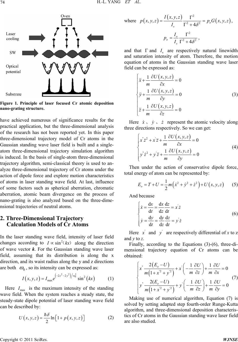
The basic principle of laser focused atomic deposition
for nanostructure is that uses radiation pressure of reso-
nant laser standing wave field to make density of atoms’
high-collimated beam to generate periodic distribution in
space, and then these neutral atoms are deposited on a
substrate to form nano-scale grating structures. Figure 1
shows the schematic of laser focused atomic deposition
for nano-grating structure.
For theoretical analysis of the laser focused atomic
deposition for nano-grating, some research teams both at
home and abroad have done one-dimensional and two-
dimensional simulations for different neutral atoms, and
*Supported by the National Natural Science Foundation of China unde
r
Grant Number 11064002 and 11061011.
H.-L. YANG ET AL.
74
Figure 1. Principle of laser focused Cr atomic deposition
nano-grating structure.
have achieved numerous of significance results for the
practical application, but the three-dimensional analysis
of the research has not been reported yet. In this paper
three-dimensional trajectory model of Cr atoms in the
Gaussian standing wave laser field is built and a single-
atom three-dimensional trajectory simulation algorithm
is induced. In the basis of single-atom three-dimensional
trajectory algorithm, semi-classical theory is used to an-
alyze three-dimensional trajectory of Cr atoms under the
action of dipole force and explore motion characteristics
of atoms in laser standing wave field. At last, influence
of some factors such as spherical aberration, chromatic
aberration, atomic beam divergence on the process of
nano-grating is also analyzed based on the three-dime-
nsional trajectories of neutral atoms.
2. Three-Dimensional Trajectory
Calculation Models of C r A t o ms
In the laser standing wave field, intensity of laser field
changes according to 2
sin
I
kx() along the direction
of wave vector k. For the Gaussian standing wave laser
field, assuming that its distribution is along the x
direction, and its waist radius along the y and z directions
are both 0
, so its intensity can be expressed as:



222
0
22 2
max
,, sin
zyw
I
xyzI ekx

(1)
Here max
I
is the maximum intensity of the standing
wave field. When the system reaches a steady state, the
steady-state dipole potential of laser standing wave field
can be described by:
 
,,ln1 ,,
2
Uxyzp xyz

where


2
22
,,
,, ,,
4o
s
Ixyz
pxyz pGxyz
I

 ,
2
22
4
o
o
s
I
pI
 ,
and that
and s
are respectively natural linewidth
and saturation intensity of atom. Therefore, the motion
equation of atoms in the Gaussian standing wave laser
field can be expressed as:


,,
10
,,
10
,,
10
Uxyz
xmx
Uxyz
ymy
Uxyz
zmz




(3)
Here
x
y
represent the atomic velocity along
three directions respectively. So we can get:
z

'' 2'
'' 2'
,,
10
,,
10
Uxyz
xzxz mx
Uxyz
yzyz my





(4)
Then under the action of conservative dipole force,
total energy of atom can be represented by:

222
1,,
2
o
ETUmxyz Uxyz 

(5)
And because
'
'
ddd
ddd
ddd
ddd
xxz
x
xz
tzt
yyz
yy
tzt
 
 
z
(6)
Here '
x
and '
are respectively differential of x to z
and y to z.
Finally, according to the Equations (3)-(6), three-di-
mensional trajectory equation of Cr atoms can be
obtained:


'' '
'2 '2
'' '
'2 '2
211
0
1
2( )11
0
1
o
o
EU UU
xx
mz mx
mxy
EU UU
yy
mz my
mxy





 





 
(7)
Making use of numerical algorithm, Equation (7) is
solved by setting adapted step fourth-order Runge-Kutta
algorithm, and three-dimensional deposition characteris-
tics of Cr atoms in the Gaussian standing wave laser field
are also studied.
(2)
Copyright © 2011 SciRes. WJNSE
75
H.-L. YANG ET AL.
3. Simulation Results and Analysis
In this paper, waist radius of Gaussian laser beam is set
to be 0100 m
425.55 n
, and parameters of Cr atoms in laser
standing wave field corresponding to
7
4
tran-
sition spectral line are respectively: transition wave-
length
7
3
SP0
m,
natural linewidth
saturation intensity
5M HZ,
s
I
= 852
Wm and detuning
. When
200MHZ
is far greater than , in order to
make the Cr atoms be focused to positions where the light
intensity is strongest through the role of the optical potential
well, laser power needed is [5]:
ks
focus 2
π
5.37 k
EI
P
.
For the longitudinal velocity = 1900 K, its most
probable velocity is
0
T
955 ms
Z
V, and at this time
focused power of Cr thermal atomic beam is =
3.93 mW [6].
focus
P
Figure 2 shows the normalized intensity distribution
of Gaussian standing wave laser field. It can be seen that
the distance between two nodes (antinodes) of standing
wave field is half the wavelength. From this we can see
that when using atom laser standing wave field to focus
the atoms, the obtained nano-stripe spacing is also half
the laser wavelength. Thus the standing wave field is
similar to “atomic lens” with atom-focus feature, and
imaging, focusing behaviors of the “lens” depend on the
characteristics of manipulated atoms. Therefore, the final
distribution of atomic beam can be adjusted by adjusting
light field intensity, light field distribution, light field
size and other parameters [7].
Figure 3 shows the trajectory of a single atom. The
atom with an initial speed 955 ms
Z
Venters into the
standing wave along the z direction, and its motion tra-
jectory will change under the effect of dipole force.
Three-dimensional trajectory of Cr atoms in laser stand-
ing wave field is shown in Figure 4. From Figure 4 it
can be seen that under ideal conditions, Cr atoms are
focused to the center of the standing wave field under the
action of potential trap.
Considering the role of y direction, Figure 5 shows
the deposition three-dimensional stripes structure of
chromium atoms under ideal conditions in the Gaussian
standing wave laser field conditions. It can be seen from
the Figure 5 that under the action of Gaussian standing
wave field, the half-wavelength periodic stripes are
formed along the x direction, and the height of the stripes
will gradually reduce starting from the center along the y
direction, besides, its full width at half maximum
(FWHM) will be on the increase, that is to say, the qual-
ity of the deposition stripes will become worse along
they direction from the center to both sides.
Figure 2. Normalized intensity of Gaussian laser standing
wave field.
Figure 3. Trajectories of single Cr atom.
Figure 4. Trajectories of Cr atoms.
However, in real conditions, the deposition of chr-
omium atoms is influenced by many factors, which will
affect the final results of the deposition. The role of the
laser standing wave field can be assimilated to a lens, so
these factors can be described by aberrations in the field
of optics including atomic beam divergence, chromatic
aberration and spherical aberration.
For thermal atomic beam, it also has some transverse
velocity, which satisfies the Gaussian distribution [8],
Copyright © 2011 SciRes. WJNSE
H.-L. YANG ET AL.
76
Figure 5. Thre e dimensional stripes of Cr atom under ideal
conditions.
corresponding to a certain divergence angle. Although
the divergence angle will be reduced after laser cooling,it
is impossible to be reduced to zero, so there is always a
certain amount of transverse velocity and divergence
angle distribution for the incident atom beam in standing
wave. Figure 6 shows the atomic trajectory affected by
atomic beam divergence.
Figure 7 is the deposition distribution and three-
dimensional stripes structure of chromium atoms under
the influence of atomic beam divergence. From the
figure we can see that the atomic beam divergence has
led to widen the atomic deposition stripes. This is
because the transverse vibration cycle of the atoms has
been changed by initial velocity x. Comparing with the
ideal deposition, many atoms are deposited around the
minimum potential field, which results in a certain width
with the grating structure.
V
As the real atomic beam is not monoenergetic atomic
beam, there is a longitudinal velocity distribution to
atomic beam, which obeys Maxwell-Boltzman distri-
bution [9]. After standing wave lens focusing, the
parallel incident atoms with different speed are not
intersected to the same point, but in a region, that is to
say, there will be a range of change to focal length,
which corresponds to chromatic aberration in particle
optics. The atomic trajectory deviation caused by long-
itudinal velocity can be expressed as [8]:
2xφad
d
z
z
V
f
aV
Figure 8 shows atomic trajectories under the influence
of chromatic aberration, from which we can see there is a
range of change to focal length for the parallel incident
atoms with different longitudinal velocity the component
after entering into the standing wave field. Figure 9 is
the deposition distribution and three-dimensional stripes
structure of chromium atoms under the influence of
Figure 6. Trajectories of chromium atoms under the influ-
ence of atomic beam divergence.
(a)
(b)
Figure 7. (a) Deposition distribution of chromium atoms
under the influence of atomic beam divergence; (b) Three
dimensional stripes of chromium atoms under the influence
of atomic beam divergence.
chromatic aberration. It can be seen from the figure there
is a broadening to deposition stripes of chromium atoms
under the influence of chromatic aberration. At this time
full width at half maximum (FWHM) and contrast of
Copyright © 2011 SciRes. WJNSE
77
H.-L. YANG ET AL.
Figure 8. Trajectories of chromium atoms under the influ
-
ence of chromatic aberration.
(a)
(b)
Figure 9. (a) Deposition dihromium atoms
d are respectively about 1.4 nm
the higher order
te
shows atomic trajectories under the influ-
en
. Conclusions
In ummary, the three-dimensional trajectory of chr-
stribution of c
under the influence of chromatic aberration; (b) Three di-
mensional stripes of chromium atoms under the influence
of chromatic aberration.
chromium atoms obtaine
and 40 by using cumulative method.
Spherical aberration results from
rms of motion equations, which leads to the actual
trajectories of atoms deviating from trajectories obtained
by the paraxial equation. The traditional method to esti-
mated spherical aberration is to expand motion equations
and deal with their high-order terms as a perturbation of
paraxial equation. Here, the impact of spherical aberr-
ation atomic beam imaging can be seen from the numeri-
cal solution of motion equations of atoms in the standing
wave field.
Figure 10
ce of spherical aberration. At first, the atoms move
parallel to the z-axis at the most probable initial velocity,
then intersect different locations after entering into the
laser standing field. Due to different incident locations,
spherical aberration is generated, ultimately making the
deposition of deposition spot diffusion which causes the
resulting widen deposition stripes. Figure 11 is the
deposition distribution and three-dimensional stripes
structure of chromium atoms under the influence of
spherical aberration. Through the numerical solution of
the motion equations, observing the impact of spherical
aberration on deposition structure is direct and accurate,
and its deficiency is not provided simple expression de-
scribing full width at half maximum (FWHM).
4
s
omium atoms is simulated by using four-order Runge-
Kutta arithmetic. Based on the discussion of reaction
with laser standing wave, the motion characteristics of
chromium atom are analyzed and the three dimensional
Figure 10. Trajectories of chromium atoms under the in-
fluence of spherical aberration.
Copyright © 2011 SciRes. WJNSE
H.-L. YANG ET AL.
Copyright © 2011 SciRes. WJNSE
78
(a)
(b)
Figure 11. (a) Deposition dihromium atoms
stripe structure is also simulated. From the simulation we
on of atoms will affect the characteristics of the
stripe.
. References
asurement and Testing, Vol. 185, No. 1, 2005, pp.
sition,” Science, Vol. 262, No.
stribution of c
under the influence of spherical aberration; (b) Three di-
mensional stripes of chromium atoms under the influence
of spherical aberration.
can see that the atoms can be focused, and the periods of
the stripe is equal to half wavelength. What’s more, the
transverse velocity, chromatic aberration and spherical
aberrati
5
[1] T. B. Li, “Nanometrology and Transfer Standard,” Shang-
hai Me
8-13.
[2] J. J. McClelland, R. E. Scholten, E. C. Palm, et al., “La-
ser-Focused Atomic Depo
5135, 1993, pp. 877-880.
doi:10.1126/science.262.5135.877
[3] J. J. McClelland, R. Gupta, R. J. Celotta and G. A.
Porkolab, “Nanostructure Fabrication by Reactive-Ion Etch-
ing of Laser-Focused Chromium on Sili
ics B, Vol. 66, No. 1, 1998, pp
con,” Applied Phys-
. 95-98.
doi:10.1007/s003400050361
[4] J. J. McClelland, W. R. Anderson, C. C. Bradley, et al.,
“Accuracy of Nanoscale Pitch Standards Fabricated by
Laser-Focused Atomic Deposition,” Journal of Research
of the National Institute of Standards and Technology,
f
Field,” Acta Physica Sinica, Vol. 55,
of Chromium Atomic Beam,” Tongji Univer-
ms in Laser Field,” Guangxi Normal
f
, pp. 1761-1768.
doi:10.1364/JOSAB.12.001761
Vol. 108, No. 2, 2003, pp. 99-113.
[5] J. J. McClelland, “Atom Optical Properties of a Stand-
ing-Wave Light Field,” Journal of the Optical Society o
America B, Vol. 12, No. 10, 1995, pp. 1761-1768.
[6] B. Ma, Y. Ma, M. Zhao, S.-S. Ma and Z.-S. Wang,
“Simulation of Sodium Atom Deposition Pattern in a La-
ser Standing Wave
2006, pp. 668-672.
[7] W. T. Zhang, “The Research of Laser Collimation and
Deposition
sity, 2008.
[8] B. H. Zhu, “The Research of Interaction and Deposition
for Chromium Ato
University, 2008.
[9] J. J. McClelland, “Atom Optical Properties of a Stand-
ing-Wave Light Field,” Journal of the Optical Society o
America B, Vol. 12, No. 10, 1995