Optics and Photonics Journal
Vol.2 No.3(2012), Article ID:22496,4 pages DOI:10.4236/opj.2012.23025
Simulation of Diode-Pumped Q-Switched Nd:YAG Laser Generating Eye-Safe Signal in IOPO Environment
Institute of Industrial Control System, Rawalpindi, Pakistan
Email: *ashrafmian@hotmail.com, mrsiddik@yahoo.com
Received June 18, 2012; revised July 20, 2012; accepted July 30, 2012
Keywords: Simulation; Diode Laser; Q-Switched Nd:YAG Laser; Eye-Safe Laser; Signal; Idler; IOPO; Rate Equations; Out-Put Power; KTP Non-Linear Crystal; Pump Beam Waist
ABSTRACT
Numerical simulation of diode-pumped Q-switched Nd:YAG laser leading to the generation of eye-safe signal in singly resonant Intra-cavity Optical Parametric Oscillator (IOPO) is presented. Starting from rate equations, the time dependent laser equations have been solved numerically, whereas the space-dependent OPO equations analytically. Our results show that 1.4 J diode laser (810 nm) pulse with 200 µsec width, delivers 30 mJ Nd:YAG laser (1064 nm) pulse with 5 n-second width. This Nd:YAG laser further generates 9 mJ eye safe signal (1570 nm) pulse with 2.5 n-second width.
1. Introduction
Compact nanosecond pulsed lasers operating in eye-safe wavelength region (1500 - 1600 nm) are of great interest in many applications such as laser radar, active imaging and remote sensing [1,2]. The conventional methods for the generation of eye-safe lasers are based upon solidstate lasers with Er3+ or Cr4+ doped media [3-6] and the Raman lasers pumped by Nd doped lasers [7-10]. Another promising approach for high-peak power eye-safe source is based upon optical parametric oscillator (OPO). The OPO has been extensively studied and developed ever since its demonstration in 1965. The main difference between Extra-cavity OPO (EOPO) and Intra-cavity OPO (IOPO) is that in IOPO, the OPO cavity is designed to be inside the cavity of the pump laser. The IOPO serves as a nonlinear cavity dumper to extract the energy stored in the intra-cavity optical field [11,12]. In recent years, KTP-IOPO pumped by passively Q-switched diodepumped Nd-doped lasers has been investigated experimentally and high-energy pulses with mJ range energy have been obtained. The conversion efficiency of the optimized Q-switched pulse energy at 1047 nm (Nd:YLF) to 1547 nm signal approached by about 47% [13]. However, the signal pulse energy is restricted mainly due to initial transmission of saturable absorber. The first KTPbased IOPO driven by a diode-pumped electro-optical Q-switched Nd:YAG laser was realized by Jin Feng et al. 15 mJ energy output at 1.57 μm wavelength with 7 ns duration at 20 Hz was demonstrated [14]. The schematic is shown in Figure 1 [15].
In this paper we simulate the diode-pumped Q-switched Nd:YAG laser generating eye-safe laser signal in IOPO environment. In the next section Diode-pumped Qswitched Nd:YAG laser is simulated.
2. Simulation of Diode-Pumped Q-Switched Pulsed Nd:YAG Laser
Taking into account the losses of pump into signal and idler radiation in the nonlinear crystal (KTP), the rate equations for the Q-switched Nd:YAG laser in IOPO [16] have been modified for diode-pumped regime and described as:
 (1)
(1)
 (2)
(2)

Figure 1. Schematic diagram of Intra-cavity optical parametric oscillator.
With

are the total losses inside the laser cavity and OPO cavity with
 and
and .
.
Here,  is the pump photon density, N is the population inversion, c is the speed of light,
  is the stimulated emission cross section of the laser medium. R1 and R2 represent the reflectivities of Nd:YAG cavity mirror.
Also,  , is the total transmission in the laser cavity. The Nd:YAG power/ energy is converted into signal and idler power/energy through nonlinear interaction in KTP and represents the conversion efficiency of the Nd:YAG pump density into signal and idler. The scheme is such that idler signal is dumped inside the IOPO. Also, lr is the length of the Nd: YAG rod and
  is the optical length of the laser cavity. The relation between the photon flux intensity Im, the photon density
 , and the complex electric field
  (in the nonlinear crystal) is expressed as:
 (3)
(3)
 (4)
(4)
The reduction of above equations to photon density equation as:
 (5)
(5)
where h is the Plank’s constant, ε0 is the permittivity of free space, nm is the refractive index at wavelength λm (m = p, s, i, corresponding to the secondary pump, signal and idler wavelengths), and ωm = 2 πνm is the radiation frequency.
Equations (1) and (2) are temporal equations and have been numerically simulated. The results are given in Figure 1. The photon density forms a pulse with width of the order of few nanoseconds. The threshold population and energy are given as:
 (6)
(6)
 (7)
(7)
The estimated values for Nth and Eth are 1.06 × 1017 cm–3 and 1.5 mJ respectively and more than [16] for lamp pumping. The main reason is that the Nd:YAG rod is transversally pumped by diode laser, which is more efficient than lamp pumping. The primary pumping pulse width is of the order of upper level’s life time of Nd:YAG laser. It has been fixed at 200 µsec in the simulation. The dynamics of sudden decrease in population from its maximum initial value, Ni (2.06 × 1018 cm–3), to the minimal value and emergence of Nd:YAG laser pulse simultaneously is represented in Figure 2.
In the next section, the simulated photon density of Nd:YAG laser will be transformed into secondary pump energy for eye-safe signal generation.
3. Eye-Safe Laser Pulse Generation in IOPO
It is convenient to define secondary pump photon energy (Nd:YAG) as
 (8)
(8)
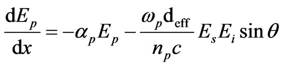
where Ep(t) is the pump electric field as is described in Equation (5) and is related to photon density. The evolution of the pump, signal and idler fields during multiple round trips in the IOPO resonator has also been simulated. Nonlinear interaction in the KTP crystal, mirror losses including absorption losses in the crystal have been incorporated in the simulation. Assuming uniform plane waves interaction and perfect phase matching, we neglect the diffraction effects. The coupled equations for the parametric interaction along the x-crystallographic axis are:
 (9)
(9)
 (10)
(10)
 (11)
(11)
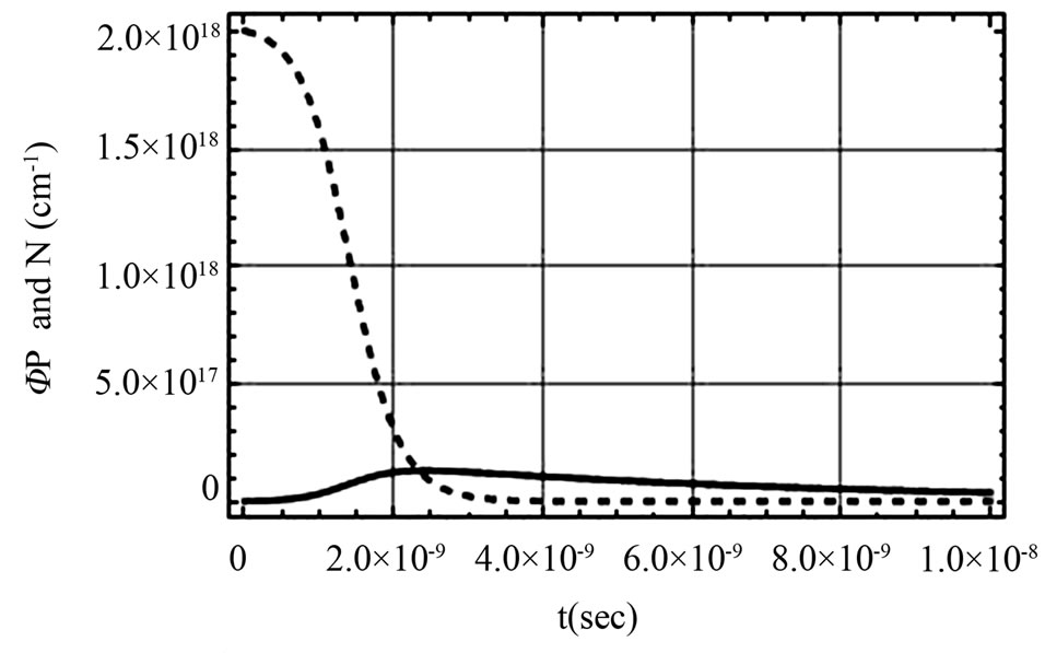
Figure 2. Nd:YAG laser photon density (in solid line) and population inversion (in dashed line) vs. time.
 (12)
(12)
It should be noted that all the fields in the Equations (9)-(12) are real. The initial phases of the signal and idler fields are not imposed by the interaction, so we suppose that they adjust themselves to maximize the energy transfer from the pump to signal and idler fields. For non-critical phase matching, θ = 90˚, it means there is no angle tuning. In order to solve above coupled wave equations, we assume that pump field Ep remains constant in entire cavity length. Consequently, analytical solution of the above coupled wave equations for signal is given as:
 (13)
(13)
where
 (14)
(14)
is the parametric gain co-efficient in cm–1 is the parametric gain co-efficient in cm–1. Here,

is the response of the idler (signal) to the nonlinear crystal KTP and  is the signal spatial mode coupling coefficient and is defined as:
 (15)
(15)
Here ws and wp are signal and pump beam waist, respectively. Nround is the number of round-trips for the gain,
 It contains threshold gain similar to Equation (6) of [17]. It is worthwhile to mention here that wp impacts the overlap between the pump and signal and determines the intra-cavity pump intensity. Furthermore, the steady state signal spot size
  is also associated with
  as follows [17]:
 (16)
(16)
with  is the optical length of the IOPO cavity and given as
  We numerically solve Equation (16) for a fix pump beam waist value and find out that root of polynomial equation in ws around that fix value of wp. The signal develops after some round trips in IOPO cavity and a time-delay

and we assume that the signal electric field at the IOPO boundary is
 (17)
(17)
Thus the expression for the signal energy is written as,
 (18)
(18)
The constants/symbols along with values used in the simulation are provided in appendix. The parameters are either fixed or simulated. First, we simulate the primary pump source of the Nd:YAG laser and estimate the pumping rate. This pumping rate estimates initial population, Ni, used in initial conditions for the solution of the differential Equations (1) and (2). Numerical simulation is performed to investigate the population as well as the photon density of Nd:YAG pulsed laser. Another important simulated parameter is secondary pump beam quality as it determines the signal’s beam quality. We fix the secondary pump beam waist and simulate the signal beam spot size and then follow the algorithm.
In the next section, the simulation results will be discussed briefly.
4. Results and Discussions
The results of Equations (8) and (18) are shown in Figure 3. It is quite evident that a 30 mJ Nd:YAG laser pulse with 5 n-second width generates a 9 mJ eye-safe signal pulse with 2.5 n-second width. The signal pulse emerges after a time delay commensurate with distance between mirrors M1 and M3.
The secondary pump beam waist is a vital design parameter. The slight change in its value will drastically affect its signal’s counterpart as is evident in Figure 4. To prove this point, we increase its value from 500 µm to


Figure 3. Secondary pump (solid) and signal energy (dashed) vs time for a) 0.05 cm (left) and b) 0.052 cm (right) pump beam waist.


Figure 4. Variation of the signal spot size (left) and corresponding energy (right) with secondary pump beam waist.
520 μm, the peak energy of the signal decreases from 9 to 4 mJ. This sensitivity of the signal spot size and corresponding peak energy with the secondary pump beam waist is highlighted and shown in Figure 4.
It is quite obvious from the above figure that the signal spot size has a linear relationship with pump beam waist and  It has been observed that the signal spatial mode coupling coefficient slightly increases with the pump beam waist but remains less than 0.68. However, the increase in secondary pump beam waist decreases the number of round trip for the gain. Consequently, the signal energy drops sharply and this trend goes on. Hence, there should be no compromise on pump beam quality. Finally, a comparison among the reference and simulated results are provided in Table 1.
5. Conclusion
Eye-safe laser has been simulated in IOPO environment in two steps. In first step, diode laser has been used as a primary pump source for the generation of 1064 nm Nd:YAG laser and in second step, Nd:YAG laser has been used as a secondary pump source for the generation of 1573 nm eye-safe laser signal. It has been shown that the eye-safe laser signal emerges after a time delay of the order of few n-seconds. The simulation results are in fairly good agreement with the referred work [15,16]. The pump beam waist is a vital design parameter. It describes the pump beam intensity. Here, it also dictates eye-safe signal pulse energy. The simulation gives reasonable results for diode laser energy less than 2 J as a primary pump source. For larger values, the secondary pump-to-signal energy ratio increases and one has to refix the parameters.

Table 1. A comparison of the simulated and referred results.
6. Acknowledgements
The authors would like to thank Dr. Rehan Akhter and Dr. A. H. Hamadani for useful discussions.
REFERENCES
- E. Gregor, D. E. Niieuwsma and R. D. Stultz, “20 Hz Eyesafe Laser Rangefinder for Air Defense,” SPIE Proceedings, Vol. 1207, 1990, pp. 124-134. doi:10.1117/12.17855
- E. Nettleton, B. W. Schilling, D. N. Barr and J. S. Lei, “Monoblock Laser for a Low-Cost, Eyesafe, Microlaser Range Finder,” Applied Optics, Vol. 39, No. 15, 2000, pp. 2428-2432. doi:10.1364/AO.39.002428.
- S. Kuck, K. Petermann, U. Pohlmann, U. Schonhoff and G. Huber, “Tunable Room Temperature Laser Action of Cr4+-doped Y3ScxAl5–xO12,” Vol. 58, No. 2, 1994, pp 153- 156.
- N. V. Kuleshov, et al., “Fluorescence Dynamics, ExcitedState Absorption and Stimulated Emission of Er3+ in KY(WO4)2,” Optics InfoBase: Journal of the Optical Society of America B, Vol. 15, No. 3, 1998, pp. 1205-1212. doi:10.1364/JOSAB.15.001205
- I. Sokolska, E. Heumann, S. Kuck and T. Lukasiewicz, “Laser Oscillation of Er3+:YVO4 and Er3+, Yb3+:YVO4 Crystals in the Spectral Range around 1.6 μm,” Applied Physics B, Vol. 71, No. 6, 2000, pp. 893-896.
- A. Sennaroglu, “Broadly Tunable Cr-Doped Solid-State Lasers in the near Infrared and Visible,” Progress in Quantum Electronics, Vol. 26, No. 6, 2002, pp. 287-352. doi:10.1016/S0079-6727(02)00016-2
- P. Cerny, H. Jelinkova, P. G. Zverev and T. T. Basiev, “Solid State Lasers with Raman Frequency Conversion,” Progress in Quantum Electronics, Vol. 28, No. 2, 2004, pp. 113-143. doi:10.1016/j.pquantelec.2003.09.003
- Y. F. Chen, “Compact Efficient All-Solid-State Eye-Safe Laser with Self-Frequency Raman Conversion in a Nd: YVO4 Crystal,” Optics Letters, Vol. 29, No. 18, 2004, pp. 2172-2174. doi:10.1364/OL.29.002172
- Y. F. Chen, “Efficient 1521-11 m Nd:GdVO4 Raman Laser,” Optics Letters, Vol. 29, No. 22, 2004, pp. 2632- 2634. doi:10.1364/OL.29.002632
- J. T. Murray, R. C. Powell, N. Peyghambarian, D. Smith, W. Austin and R. A. Stolzenberger, “Generation of 1.5 μm Radiation through Intracavity Solid State Raman Shifting in Ba(NO3)2 Nonlinear Crystals,” Optics Letters, Vol. 20, No. 9, 1995, pp. 1017-1023. doi:10.1364/OL.20.001017
- Y. Yashkir and H. M. Van Driel, “Passively Q-Switched 1.57-μm Intracavity Optical Parametric Oscillator,” Applied Optics, Vol. 38, No. 12, 1999, pp. 2554-2559. doi:10.1364/AO.38.002554
- A. Agnesi, S. Dell’aequa and G. Reali, “Diode-Pumped Quasi-Cw Intracavity Optical Parametric Oscillator at 1.57 μm with Efficient Pulse Shortening,” Applied Physics B: Lasers and Optics, Vol. 70, No. 6, 2000, pp. 751- 753. doi:10.1007/PL00021130
- W. Zendzian, J. K. Jabczynski, J. Kwiatkowski and K. Kopczynski, “300-kW, Eye-Safe Intracavity OPO Transmitter,” Proceedings of the SPIE, Vol. 6952, 2008, Article ID: 69520U.
- F. Jin, G. Zhai, J. Li, N. Ma and S. S. Shi, “All Solid State Eye-Safe Optical Parametric Oscillators,” Laser Technology, Vol. 26, No. 3, 2002, pp. 201-203.
- Y.-Y. Wang, K. Zhong and D.-G. Xu, “High-Energy Pulsed Eye-Safe Intracavity Optical Parametric Oscillator at 1.57 μm,” Proceedings of the SPIE, Vol. 7276, 2008, Article ID: 727603.
- R. Dabu, A. Stratan and C. Fenic, “Intracavity Pumped Nanosecond Optical Parametric Oscillator Emitting in the Eye-Safe Range,” Applied Optics, Vol. 40, No. 24, 2001, pp. 4334-4340.
- J. G. Miao, H. K. Bian and B. S. Wang, “Low Threshold Narrow Pulse Width Intra-Cavity Optical Parametric Oscillator at 1573 nm,” Optics Communications, Vol. 265, No. 1, 2006, pp. 349-353. doi:10.1016/j.optcom.2006.03.040
Appendix
Constants and Symbols


NOTES
*Corresponding author.