Optics and Photonics Journal
Vol.2 No.1(2012), Article ID:18282,7 pages DOI:10.4236/opj.2012.21007
Attenuation in a Cylindrical Left Handed Material (LHM) Wave-Guide Structure
Physics Department, Al-Azhar University, Gaza, Palestine
Email: H.mousa@alazhar-gaza.edu.ps
Received January 7, 2012; revised February 8, 2012; accepted February 17, 2012
Keywords: Left handed material; TM waves; TE waves; Attenuation constant; Waveguides; Superconductor; metal
ABSTRACT
This paper tackles the wave attenuation along with a cylindrical waveguides composed of a left Handed material (LHM), surrounded by a superconducting or metal wall. I used the transcendental equations for both TE and TM waves. I found out that the waveguide supports backward TE and backward TM waves since both permittivity and magnetic permeability of LHM are negative. I also illustrated the dependence of the TE and TM wave attenuation on the wave frequency and the reduced temperature of the superconducting wall ( ). Attenuation constant increases by increasing the wave frequency and it shows higher values at higher
 . Lowest wave attenuation and the best confinement are achieved for the thickest TE waveguide. LHM-superconductor waveguide shows lower wave attenuation than LHMmetal waveguide.
1. Introduction
Recently, there has been a great interest in new type of electromagnetic materials called left-handed media [1]. Over the past, fifty years, Veselago was the first scientist to consider the left-handed meta-material (LHM). He defined it as media with simultaneously negative and almost real electric permittivity and magnetic permeability in some frequency range [2]. The electric and magnetic fields form a left-handed set of vectors with the wave vector [3]. These materials have exhibited unique properties, such as Snell law and Doppler shift. The negative refraction index has been recently observed by Shelby, Smith, and Shultz [4] in completely different systems. Negative refraction allows the fabrication of perfect lens [5] where an object can be reconstructed without any diffraction error and super-lens [6,7], and focusing by Plano-concave lens [8]. They can be made to be anisotropic and have indefinite index meta-materials which can be used to make hyper-lens [9]. This range of properties opens infinite possibilities to use meta materials in frequencies from micro-wave up to the visible wave. Circular and a planer waveguides have been widely applied in receivers of radio telescope [10,11]. Shabat and Mousa [12-15] discussed the propagation characteristics of nonlinear electromagnetic TE surface waves in a planer waveguide structure of a lateral antiferromagnetic/nonmagnetic super-lattices (LANS) film bounded by a nonlinear dielectric cover and a lefthanded substrate. The backward and bi-stability behaviors have been noticed clearly. Huang, et al. [16] considered the wave propagation along with a cylindrical nanowire waveguide made of indefinite index meta-materials. They found out that the backward-wave modes can have very large effective index. These nanowires can be used as an ultra-compact optical buffer in integrated optical circuits. Yeap, et al. have discussed and developed a novel technique to compute the attenuation of waves propagating in circular waveguides with lossy and superconducting walls [17]. They have compared their results with by using the Stratton’s method and the approximate perturbation method. The results from the three methods agree very well at a reasonable range of frequencies above the cutoff. The propagation of waves in superconductor media have drowned much attention and consideration [18]. The use of superconducting thin films in transmission line is advantageous for signal processing because films are low loss and they are with wide bandwidth [19]. The loss can be described in terms of the surface resistance of the superconductor and it is also related to the attenuation constant of the superconductor. It can be exerpted from the study of its propagation characteristics.
A superconductor like Yttrium barium copper oxide (YBCO), is a famous “high-temperature superconductor”, achieves prominence because it is the first material to achieve superconductivity above (77 K), the boiling point of liquid nitrogen. It is associated with the formula YBa2Cu3O7−x The superconducting properties of YBa2 Cu3O7−x are sensitive to the value of x, its oxygen content with 0 ≤ x ≤ 0.65. R.D Black et al. [20]. It describes a high-temperature superconducting-receiver system for use in nuclear magnetic resonance (NMR) microscopy. The implementation of thin-film YBCO receiver coils has improved the signal-to-noise ratio of nuclear magnetic resonance spectrometers by a factor of 3 compared to that achievable with conventional coils. This improvement enables the data acquisition time to be reduced by an order of magnitude. These coils are also potential applications in low-frequency magnetic resonance imaging (MRI). They are used in hospitals and clinics. The feasibility of applying high-temperature superconductor (HTS) technology to nonreciprocal microwave devices has been demonstrated in the form of isolators and circulators. They are used widely to achieve stability, reliability, and reproducibility in microwave circuit performance [21]. Pure YBa2Cu3O7−x ceramics normally display superconductivity and metallic conductivity below and above the critical temperature of the superconductor  respectively. Mohazzab, et al. described the synthesis of epoxy-modified YBCO ceramics and evaluates the semiconducting properties at temperature above
  [22]. Of the new ceramic superconductors, only YBa2Cu3O7−x has been developed in thin-film form to the point of practical applications, and several devices are available. Intensive materials research have resulted in techniques, notably laser-ablation and radio-frequency sputtering.
In this analysis, a theoretical study of the propagation characteristics of TE and TM waves guided by an optical structure is presented. This structure consists of a left Handed material (LHM) cylinder with superconducting walls like YBa2Cu3O7−x.  and
and  are electric permittivity and magnetic permeability of LHM respectively.
2. Constitutive Relations for TE and TM Waves
In this context, the structure geometry of the problem considered is shown in Figure 1. I considered wave propagation on a cylindrical waveguide. The axis of the waveguide is along with the z direction.
The longitudinal electric and magnetic fields  and
and  respectively, propagating in the waveguide can be derived by aid of Helmholtz’s wave equation [23].
Decomposing Helmholtz’s wave equation into a radial and a longitudinal part in cylindrical coordinates for the electric field  yields:
 (1)
(1)

Figure 1. The proposed cylindrical waveguide composed of LHM and superconducting wall.
A plane wave solution for the electric field of the form

is substituted into Equation (1) as:
 (2a)
(2a)
with  where
where  represents the wave angular frequency,
  is the wave number in free space
 ,
,  and
and  are the dielectric permittivity and magnetic permeability of free space respectively.
  is the propagation constant. Both a negative dielectric permittivity and permeability are written as [3]:
 , (2b)
 and resonance frequency
 ,
,  is the magnetic permeability of LHM and
  is the electric permittivity of LHM.
Equation (2a) can be split into two equations by a separation of variables with the form:
 (3a)
(3a)
 (3b)
(3b)
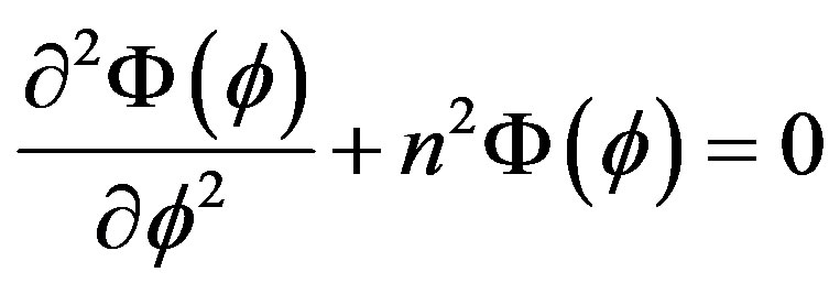
Equation (3b) describes a simple harmonic oscillator and Equation (3a) is one form of the Bessel equations, whose solutions are the Bessel functions [24]. The following set of field equations are:
 (4a)
(4a)
 (4b)
(4b)
where  and
and  denote the coefficients of the longitudinal fields,
  is the radial distance ,
  is called the Bessel function of the first kind and
  is the order of the Bessel function.
The propagation constant  is a complex variable which constitutes a phase constant
  and an attenuation constant
  as:
as:
 . (4c)
By Maxwell’s curl equations, the transverse field components can be written as:
 (5a)
(5a)
 . (5b)
Substituting Equation (4a) and Equation (4b) into Equation (5a) and Equation (5b), yields
 (6a)
(6a)
and
 (6b)
(6b)
At the wall, the tangential electric and magnetic fields  and
and  respectively are related to a surface impedance
  by [24,25]:
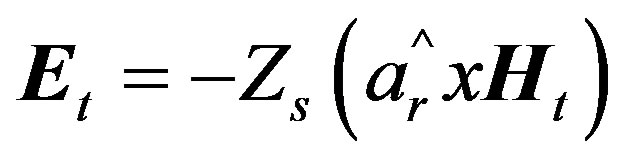 . (6c)
With
 (6d)
(6d)
By substituting Equation (6d) into Equation (6c) one obtains:
 (7a)
(7a)
and
 , (7b)
 can be expressed in terms of electrical properties of the wall material (superconductor) as:
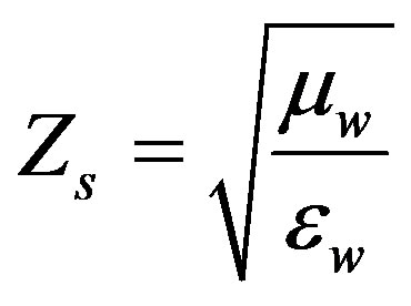 , (8)
, (8)
 is the permittivity of the superconductor. It is complex with the form [26]:
 . (9a)
where
 (9b)
(9b)
 is the field penetration depth at temperature T = 0 K,
  is the conductivity of the superconductor and
  is the critical temperature of the superconductor.
  is called the reduced temperature of the superconductor. At the boundary of the wall (
 ), by substituting Equation (4a), Equation (6a) and Equation (8) into Equation (7a), and dividing by
 , one obtains:
 . (10)
By substituting Equation (4b), Equation (6b) and Equation (8) into Equation (7b), and dividing it by , one gets:
 (11)
(11)
Equation (10) and Equation (11) constitute a homogeneous system which admits a non trivial solution only in case its determinant is zero. Solving the determinants of the coefficients  and
and  in Equation (10) and Equation (11) results in the following transcendental equation:
 (12)
(12)
The roots of Equation (12) are the allowed values of the propagation constant . Thus, it determine the characteristics modes of propagation. For each value of
  there is infinity of roots, any one of which can be denoted by the subscript
 . Any root of Equation (12) can then be designated by
 . In Equation (12), since TE modes are determined by roots of
  [23]the attenuation constant of TE modes (
 ) can be obtained from
  by extracting the imaginary part of Equation (4c) .
An alternate form of the Equation (12) is required for TM modes by substituting Equation (4a), Equation (6a) and Equation (8) into Equation (7a), and dividing it by , then the result is :
 (13)
(13)
By substituting Equation (4b), Equation (6b) and Equation (8) into Equation (7b), and dividing it by , the result is :
 (14)
(14)
In same way, the transcendental equation of TM modes is:
 (15)
(15)
Since TM modes are determined by roots of
 , the attenuation constant of TM modes (
 )
)
can be obtained [22].
3. Numerical Results and Discussion
In this paper, the numerical calculations for LHM cylinder with a superconducting wall like YBa2Cu3O7−x, are taken with the following parameters: 
 and
and  [3],
[3],
 and
and ,
,  [27]. The frequency range in which both
  and
and  are negative is from 4 to 6 GHz. In this range, and at a definite thickness such as
 , the solution for the phase constant
  and attenuation constant
  of TE waves is found by solving Equation (12). Figure 2 displays the phase constant
  of TE wave versus the wave frequency (
 ) of the first band for different values of reduced temperature of the superconductor wall
 ; (0.7, 0.8, 0.9). Both the wave phase velocity
  and the group velocity
  dispersions are affected by the reduced temperature of the superconductor
 , where
  decreases to positive values, and
  decreases to negative values as
  increases; This means that the backward-TE waves are observed as effect of the LHM cylinder of increasing
 . These backward TE waves have very large propagation lengths which is the same result as reported by Huang, et al. [16]. These waveguides can be used as phase shifters and filters in optics and telecommunications. Figure 3(a) displays the attenuation constant
  of the second band of TE waves versus the wave frequency for increasing values of
 . It illustrates that the attenuation constant increases by increasing the wave frequency as Yeap et al. reported [17]. Higher attenuation of waves is also observed at lower frequencies by increasing
 , (i.e., for curves (“1”, “2” and “3”) )where
  increases to the values (0.5, 0.7 and 0.9) the higher attenuation of frequency value is respec-

Figure 2. Dispersion curves of the first band TE guided waves of LHM-superconductor waveguide for (1) , (2)
, (2)  and (3)
 . The curves are labeled with values of
 ,
, 
 ,
,  ,
,  ,
,  and
and .
.
tively observed in (5.8, 5.7 and 5.6 GHz). By Equation (8), Equation (9a) and Equation (9b), increasing  by increasing
  will decreases
 . As a result, high
  and then high attenuation is achieved. The solution for the attenuation constant of TM waves is found by solving Equation (15). Figure 3(b), describes the variation of the attenuation of the second band of TM guided waves for different values of reduced temperature of the wall. It displays that the attenuation is increased to negative values by increasing wave frequency and it indicates more attenuation at higher
 . I believe that these negative values of attenuation could be a result of the effect of the negative values of
 . It affect the dispersion and decay constant of TM waves as noticed in [16, 28]. In the superconductor,
  values decreases from
  to
to
 in the frequency range 4 to 6 GHz and at
 . As a comparison between the results of Figures 3(a) and (b), the TE waveguide with a = 3 mm has lower attenuation than the TM wave-guide.
By increasing the band’s order  to the values (1, 2, 3, 4, 5, 6, 7 and 8), roots of
  are increasing to the values (−1.84, −3, −4.2, −5.3, −6.4, −7.5 and −8.577) respectively. As a result, high attenuation of waves is realized at a higher band’s order.
In Figures 4(a) and (b), the wave frequency has been plotted against the attenuation constant for the first five
 (a) (b)
Figure 3. Attenuation curves of the second band (a) TE and (b) TM guided waves of LHM-superconductor waveguide for (1) , (2)
, (2)  and (3)
 . The curves are labeled with values of
  and
and .
.
 (a) (b)
Figure 4. (a) and (b): Attenuation curves of the first five bands TM guided waves of LHM-superconductor waveguide for ,
,  and
and .
.
TM bands. By increasing the band's order  to the values (1, 2, 3, 4 and 5), roots of
  are (−3.83, 30.56, −6.38, 49.3 and −8.7) respectively. For the odd band's order, (i.e., (1, 3, 5)) as the frequency decreases further to cutoff, the attenuation rises to high negative values, signals propagation become almost impossible. The attenuation is decreased to high negative values as compared to attenuation of even band's order which is increased to small negative values by increasing frequency.
The effect of the waveguide thickness on attenuation of the second band of TE waves is noticed in Figure 5(a). By decreasing the radius  to the values 10 mm, 7 mm, 3 mm, the attenuation increases to the values of (0.0015, 0.0028, 0.0084) respectively at frequency 5.6 GHz. The attenuation of the second band of TM waves is also noticed in Figure 5(b). As the radius
  decreases to the previous values, the magnitude of the TM attenuation rises to larger values nearly (−40).
This means that, in this waveguide, the lowest wave attenuation and the best confinement are achieved for the thickest TE waveguide. Figure 6, describes the attenuation curves when the superconductor wall YBa2Cu3O7−x is replaced by a metal like ferrite. Both  and
and  are replaced by
  and
and  respectively. According to Lichtenecker’s formula and in frequency range (4 to 5.8 GHz) [29], the estimated value of the dielectric permittivity of ferrite is
  and the magnetic permeability is
 . Figure 6(a) displays the attenuation constant of the second TE band versus the
 (a) (b)
Figure 5. (a) Attenuation curves of the second (a) TE and (b) TM band of LHM-superconductor waveguide for (1) a = 10 mm, (2) a = 7 mm, and (3) a = 3 mm. The curves are labeled with values of , and
, and .
.
 (a) (b)
Figure 6. Attenuation curves of the second (a) TE band and (b) TM band of LHM-metal waveguide for (1) a = 10 mm, (2) a = 7 mm, and (3) a = 3 mm. The curves are labeled with values of  and
and .
.
wave frequency for different values of LHM-Ferrite radius. By decreasing the radius  to the values 10 mm, 7 mm, 3 mm, the attenuation increases to the values of (−200, −280, −660) respectively at frequency 5.6 GHz. For the same range of a, the TM second band’s attenuation increases to the values of (160, 260, 660) respectively at frequency 5.6 GHz as displayed by Figure 6(b).
As a comparison between Figures 5 and 6, the implementation of YBa2Cu3O7−x has reduced the TE and TM wave attenuation ratio by a factor of 105 and 10 respectively as compared to that achievable with LHM-Ferrite structure.
4. Conclusion
The attenuation characteristics of both TE and TM waves in a waveguide structure containing LHM-superconductor or LHM-metal are dicussed. I found out that, LHM stimulate the modes to be backward of large propagation lengths. The lowest wave attenuation and the best confinement are achieved for the thickest TE waveguide. I compared the loss of LHM-superconductor waveguide with that of LHM-metal waveguide. The LHMsuperconductor waveguide is able to reduce the propagation losses, and to increase the mode’s propagation lengths which are very promising results in designing some future microwave devices.
REFERENCES
- L. Hu and S. T. Chui, “Characteristics of Electromagnetic Wave Propagation in Uniaxially Anisotropic Left-Handed Materials,” Physical Review: B, Vol. 66, No. 8, 2002, p. 085108. doi:10.1103/PhysRevB.66.085108
- V. G. Veselago, “The Electrodynamics of Substances with Simultaneously Negative Values of Permittivity and Permeability,” Soviet Physics Uspekhi, Vol. 10, No. 4, 1967, p. 509. doi:10.1070/PU1968v010n04ABEH003699
- I. V. Shadrivov, A. A. Sukhorakov and Y. S. Kivshar, “Nonlinear Surface Waves in Left-Handed Material,” Physical Review: E, Vol. 69, No. 1, 2004, p. 016617. doi:10.1103/PhysRevE.69.016617
- R. A. Shelby, D. R. Smith and S. Schultz, “Microwave Transmission through a Two-Dimensional, Isotropic, LeftHanded Meta-Material,” Applied Physics Letter, Vol. 78, No. 4, 2001, pp. 489-491. doi:10.1063/1.1343489
- N. Garcia and M. Nieto, “Left-Handed Materials Do Not Make a Perfect Lens,” Physical Review Letter, Vol. 88, No. 20, 2002, p. 207403. doi:10.1103/PhysRevLett.88.207403
- J. B. Pendry, “Negative Refraction Makes a Perfect Lens,” Physical Review Letter, Vol. 85, No. 18, 2000, pp. 3966. doi:10.1103/PhysRevLett.85.3966
- W. T. Lu and S. Sridhar, “Flat Lens without Optical Axis: Theory of Imaging,” Optics Express, Vol. 13, No. 26, 2005, pp. 10673-10680. doi:10.1364/OPEX.13.010673
- P. Vodo, W. T. Lu, Y. Huang and S. Sridhar, “Negative Refraction and Plano-Concave Lens Focusing in OneDimensional Crystals,” Applied Physics Letter, Vol. 89, No. 8, 2006, p. 084104. doi:10.1063/1.2338644
- I. I. Smolyaninov, Y. J. Hung and C. C. Davis, “Magnifying Superlens in the Visible Frequency Range,” Science, Vol. 315, No. 5819, 2007, pp. 1699-1701. doi:10.1126/science.1138746
- J. R. Tucker and M. J. Feldman, “Quantum Detection at Millimeter Wavelengths,” Review of Modern Physics, Vol. 57, No. 4, 1985, pp. 1055-1113. doi:10.1103/RevModPhys.57.1055
- M. J. Wengler, “Sub-Millimeter-Wave Detection with Superconducting Tunnel Diodes” Proceedings of the IEEE, Vol. 80, No. 11, 1992, pp. 1810-1826. doi:10.1109/5.175257
- H. M. Mousa, M. M. Shabat, H. Khalil and D. Jager, “Non-Linear Surface Waves along the Boundary of Magnetic Superlattices (LANS),” Proceedings of SPIE, Vol. 5445, 2003, pp. 274-278. doi:10.1117/12.560650
- H. M. Mousa and M. M. Shabat, “Non Linear TE Surface Waves on Magnetic (LANS) Superlattices,” International Journal of Modern Physics B, Vol. 19, No. 29, 2005, pp. 4359-4369. doi:10.1142/S0217979205032796
- H. M. Mousa and M. M. Shabat, “ Non linear TE Surface in a Left-Handed Material and Superlattices Wave-Guide structures,” International Journal of Modern Physics B, Vol. 21, No. 6, 2007, pp. 895-906. doi:10.1142/S0217979207036746
- M. M. Shabat and H. M. Mousa, “The Propagation of Electromagnetic TE Surface Waves in Magnetic Superlattices (LANS) Film,” Proceedings of SPIE, Vol. 6582, 2007. doi:10.1117/12.721062
- Y. J. Huang, W. T. Lu and S. Sridhar, “Nanowire Waveguide Made from Extremely Anisotropic Meta-Materials,” Physical Review: A, Vol. 77, No. 6, 2008, p. 063836. doi:10.1103/PhysRevA.77.063836
- K. H. Yeap, C. Y. Tham, K. C. Yeong and H. J. Woo, “Wave Propagation in Lossy and Superconducting Circular Waveguides, “Radioengeneering, Vol. 19, No. 2, 2010, pp. 320-325.
- M. M.Shabat and D. Jager, “Magnetostatic Surface Wave in a Superconductor-Ferrite Structure,” 5th International Workshop on Integrated Nonlinear Microwave and Millimeter wave Circuits, Dusiburge, 1-2 October 1998.
- C. J. Wu, “Tunable Microwave Characteristics of a Superconducting Planar Transmission Line by Using a Nonlinear Dielectric Thin Film,” Journal of Applied Physics, Vol. 87, No. 1, 2000, p. 493. doi:10.1063/1.371889
- R. D. Black, T. A. Early, P. B. Roemer, O. M. Mueller, A. Campero, L. G. Turner and G. A. Johnson, “A High-Temperature Superconducting Receiver for Nuclear Magnetic Resonance Microscopy,” Science, Vol. 259, No. 5096, 1993, pp. 793-795. doi:10.1126/science.8430331
- E. Denlinger, R. Paglione, D. Kalokitis, E. Belohoubek, A. Pique, X. D. Wu, T. Venkatesan, A. Fathy, V. Pendrick, S. Green and S. Mathews, “Superconducting Nonreciprocal Devices for Microwave Systems,” IEEE Microwave and Guided Wave Letters, Vol. 2, No. 11, 1992, pp. 449-451. doi:10.1109/75.165640
- G. Mohazzab and I. M. Low, “Electrical Properties of Epoxy-Modified YBCD Semiconducting Ceramics,” Journal of material Science Letters, Vol. 16, No. 1, 1987, pp. 88-90. doi:10.1023/A:1018517305021
- J. A. Stratton, “Electromagnetic Theory,” McGraw-Hill, Boston, 1941, pp. 527-542.
- D. K. Cheng, “Field and Wave Electromagnetics,” 2nd Edition, Addison Wesley, Inc., Boston, 1989, pp. 547- 557.
- C. Y. Tham, A. Mccowen and M. S. Towers, “Modelling of PCD Transients with Boundary Elements Method of Moments in the Frequency Domain,” Engineering Analysis with Boundary Elements, Vol. 27, No. 4, 2003, pp. 315-323. doi:10.1016/S0955-7997(02)00119-4
- M. Tsutsumi, T. Fukusako and S. Yoshida, “Propagation Characteristics of the Magneto-Static Surface Wave in the YBCO-YIG Film-layered Structure,” IEEE Transactions on Microwave Theory and Techniques, Vol. 44, No. 8, 1996, p. 1410. doi:10.1109/22.536023
- D. Mihalache, R. G. Nazmitdinov and V. K. Fedyanin, “Nonlinear Optical Waves in Layered Structure,” Soviet Journal of Nuclear Physics, Vol. 20, 1989, pp. 86-107.
- H. M. Mousa and M. M. Shabat, “TM Plasmons in a Cylindrical Superlattices (LANS) Waveguide Structure,” Journal of Nanoand Electronic Physics, Vol. 3, No. 3, 2011, pp. 15-17.
- H. Ebara, T. Inoue and O. Hashimoto, “Measurement Method of Complex Permittivity and Permeability for a Powdered Material using a Waveguide in Microwave Band,” Science and Technology Advanced Material, Vol. 7, No. 1, 2006, pp. 77-83. doi:10.1016/j.stam.2005.11.019