Journal of Surface Engineered Materials and Advanced Technology
Vol.05 No.04(2015), Article ID:60770,8 pages
10.4236/jsemat.2015.54024
Metal Fluorides Produced Using Chlorine Trifluoride Gas
Hitomi Matsuda1, Hitoshi Habuka1*, Yuuki Ishida2, Toshiyuki Ohno3
1Department of Chemical and Energy Engineering, Yokohama National University, Yokohama, Japan
2National Institute of Advanced Industrial Science and Technology, Tsukuba, Japan
3FUPET, Tsukuba, Japan
Email: *habuka1@ynu.ac.jp
Copyright © 2015 by authors and Scientific Research Publishing Inc.
This work is licensed under the Creative Commons Attribution International License (CC BY).
http://creativecommons.org/licenses/by/4.0/


Received 12 September 2015; accepted 26 October 2015; published 29 October 2015
ABSTRACT
For developing coating materials, the fluorides of scandium, lanthanum, strontium, barium, magnesium and aluminum were produced from their oxides and chlorides by means of exposure to chlorine trifluoride gas at temperatures between room temperature and 700˚C. The metal chlorides could be easily fluorinated even at room temperature, while the metal oxides required temperatures higher than 300˚C. After the heating in ambient hydrogen at 1100˚C, the fluorides of lanthanum and barium showed very low weight losses at 1100˚C, although the weights of the other fluorides significantly decreased. These materials may work as protective films against corrosive and high temperature environments, particularly when using the chlorine trifluoride gas.
Keywords:
Metal Fluoride, Metal Oxide, Chlorine Trifluoride, Synthesis, Coating Film Material

1. Introduction
Chemical vapor deposition (CVD) can produce various high quality and functional material films [1] . In the CVD reactor, a film is formed not only on the substrate surface, but also on the surface of various reactor parts, such as the susceptor, gas distributor and exhaust. The unnecessary films formed near the substrate often emit many small particles that cause serious film defects, such as hillocks and stacking faults. Thus, such films are removed by means of a cleaning process using highly reactive gases, such as hydrogen chloride, chlorine trifluoride, fluorocarbons and nitrogen fluoride along with thermal and/or plasma assistance.
Chlorine trifluoride gas is expected to be widely used for various applications, such as CVD reactor cleaning, etching, etc., because it has a very high reactivity that produces various fluorides [2] . For the silicon carbide CVD reactor, the cleaning process has been very difficult except when using chlorine trifluoride gas [3] - [14] , because of the significantly stable chemical nature of silicon carbide [2] .
From a practical viewpoint, the surfaces of the susceptor and other reactor parts should not suffer from any damage due to the corrosive gases during the cleaning process. Thus, the coating film is the key technical issue for using the chlorine trifluoride gas. In order to develop a coating film applicable for the cleaning process using the chlorine trifluoride gas, fluorides are the initial candidates. The chlorine trifluoride gas reacts with various materials to form volatile and non-volatile fluorides [2] . When the material surface is covered with the non-vo- latile fluorides, this fluoride film is expected to have no further reaction with the chlorine trifluoride gas. The convenient way to produce the fluoride is to utilize the chemical reaction of cheap materials, such as oxides and chlorides, with the chlorine trifluoride gas.
In addition to the non-corrosive nature, the candidate materials for the coating film should have a non-volatile nature, because the CVD process is usually performed at high temperatures [1] . The coating materials should have high melting points, specifically higher than 1500˚C for the silicon carbide CVD. Unfortunately, only a few fluorides have such high melting points [15] . However, various positions in the CVD reactor have various local temperatures, lower than the susceptor, depending on the heating conditions. At the low local temperature locations, many metal fluorides are expected to be applicable as the coating film material.
In this study for developing the high temperature coating materials, various metal fluorides were synthesized by the chemical reaction of the chlorine trifluoride gas with metal oxides and metal chlorides. Additionally, the obtained fluorides were heated in ambient hydrogen at various temperatures for evaluating their non-volatile nature.
2. Experimental Procedure
Figure 1 shows the reactor used in this study. This reactor consisted of a gas supply system, a quartz chamber and six infrared lamps. The gas supply system introduces the chlorine trifluoride gas and nitrogen gas. This reactor has a small cross section in order to achieve a high consumption efficiency of the chlorine trifluoride gas. The height and width of the quartz chamber were 10 mm and 40 mm, respectively. Small silicon carbide plates, having dimensions of 3 cm × 3 cm, were placed at the bottom of the quartz chamber. The rectangular-shaped quartz tray containing the source material’s powder (about several tens mg) was placed on the silicon carbide plate. The silicon carbide plate was heated by infrared rays emitted from halogen lamps through the quartz chamber walls. The electric power to the six infrared lamps was adjusted based on the temperatures previously measured in ambient nitrogen. For heating the obtained fluorides at various temperatures in the ambient hydrogen, another reactor with the same design was used.
Figure 2(a) shows the typical process for the exposure to chlorine trifluoride gas in this study. First, the susceptor was heated to 300˚C, 500˚C and 700˚C in the ambient nitrogen, except for the case at room temperature. Next, it was exposed to the chlorine trifluoride gas (>99.9%, Kanto Denka Kogyo Co., Ltd., Tokyo) at 100% and 50 - 100 sccm without the nitrogen gas. After exchanging the ambient gas from the chlorine trifluoride to nitrogen for terminating the chemical reaction, the sample was cooled to room temperature. Before and after the exposure to the chlorine trifluoride gas, the appearance of the sample was observed by visual inspection. The chemical bonds of the obtained materials were evaluated by the X-ray photoelectron spectroscopy (Quantera SXM, ULVAC-PHI Corp., Tokyo, Japan).
Figure 2(b) shows the process for the heating in ambient hydrogen. First, the susceptor was heated to 700˚C
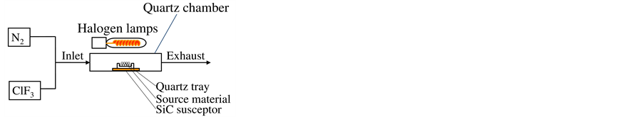
Figure 1. Reactor for exposing source materials to chlorine trifluoride gas.

Figure 2. Process for exposing source materials to (a) chlorine trifluoride gas and (b) ambient hydrogen.
and 1100˚C in ambient nitrogen. Next, it was exposed to the hydrogen gas (99.9999%, Sumitomo Seika Kogyo, Tokyo) at 100% and 1000 sccm without the nitrogen gas. After exchanging the ambient gas from hydrogen to nitrogen, the sample was cooled to room temperature. Before and after exposure to the hydrogen gas, the appearance and chemical bonding conditions of the sample were evaluated by visual inspection and XPS, respectively.
3. Results and Discussion
3.1. Scandium Compounds
The scandium compounds were first evaluated, because the melting point of the scandium fluoride, 1552˚C, is the highest of the metal fluorides. As shown in Figure 3, the scandium oxide was exposed to the chlorine trifluoride gas at room temperature, 300˚C and 700˚C. Figure 3(a) shows the appearance of the scandium oxide before exposure to the chlorine trifluoride gas. It had a white powder appearance which did not change after exposure at every temperature, as shown in Figures 3(b)-(d). However, the decrease in its amount was considerable. At room temperature, 300˚C and 700˚C, the weight decrease was 39%, 7% and 21%, respectively. The percent decrease showed no obvious relationship to the temperature. However, the loss due to the reaction with the chlorine trifluoride gas was clearly recognized, because the change from scandium oxide (Sc2O3) to scandium fluoride (ScF3) should cause a weight increase of about +47%. For clarifying the details of the materials change, the X-ray diffraction patterns should be studied.
Figure 4 is the XPS spectra showing the chemical bonding of the obtained material from the scandium oxide. As shown in Figure 4(a), fluorine was detected along with oxygen in the material obtained at room temperature. The contained oxygen was considered to be that not fully replaced with fluorine. After exposure at 300˚C, distinct fluorine peaks were detected; the oxygen peaks became significantly small, as shown in Figure 4(b). In Figure 4(c), the material obtained after exposure at 500˚C clearly showed the fluorine and scandium peaks, similar to those at 300˚C. This indicated that the percent of scandium fluoride in the material obtained from scandium oxide significantly increased at temperatures higher than 300˚C. The composition of the metal fluoride evaluated from the XPS is listed in Table 1. The percent of scandium oxide was less than 60% at room temperature; it increased to 99% at 300˚C and 500˚C.
Next, the scandium chloride was exposed to the chlorine trifluoride gas at various temperatures. The appearance of the scandium chloride is shown in Figure 5. Before exposure, the scandium chloride was a white powder, as shown Figure 5(a). The weight decreased after exposure to the chlorine trifluoride gas at room temperature, although the appearance seemed to have expanded, as shown in Figure 5(b). As shown in Figure 5(c) and Figure 5(d), the appearance and the weight at 500˚C and 700˚C changed similar to that at 300˚C. The weight decrease greater than 50% was significant, because the weight decrease from scandium chloride to its fluoride is theoretically only 32%.
Figure 6 shows the XPS spectra of the samples shown in Figure 5. After exposure at room temperature, the fluorine peaks were clearly observed, while there were no chlorine peaks, as shown in Figure 6(a). At 500˚C
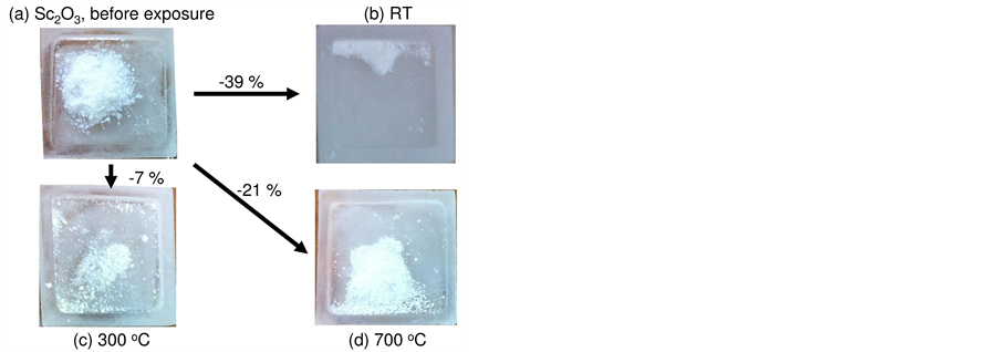
Figure 3. Appearance of scandium oxide, Sc2O3, (a) before and after exposure to chlorine trifluoride gas at (b) room temperature, (c) 300˚C and (d) 700˚C.

Figure 4. X-ray photoelectron spectra of scandium oxide, Sc2O3, after exposure to chlorine trifluoride gas at (a) room temperature, (b) 300˚C and (c) 500˚C.

Table 1. Concentrations of produced fluorides.
![]()
Figure 5. Appearance of scandium chloride, ScCl3・6H2O, (a) before and after exposure to chlorine trifluoride gas at (b) room temperature, (c) 300˚C and (d) 700˚C.
![]()
Figure 6. X-ray photoelectron spectra of scandium chloride, ScCl3・6H2O, before and after exposure to chlorine trifluoride gas at (a) room temperature, (b) 500˚C and (c) 700˚C.
and 700˚C, as shown in Figure 6(b) and Figure 6(c), respectively, chlorines contained in the source material did not remain, while distinct fluorine peaks were present. The concentration of the scandium fluoride was nearly 99% due to the process at temperatures higher than room temperature.
In order to compare the ease of fluorination, the fluorine to scandium ratio, F/Sc, is shown in Figure 7. When the scandium oxide was exposed to the chlorine trifluoride gas at room temperature, the F/Sc value was still near 1. At 300˚C, the F/Sc value increased to nearly 3, while that at high temperatures tended to be saturated at 3.
The scandium chloride showed an F/Sc value near 3 after exposure to the chlorine trifluoride gas even at room temperature. The exposure to chlorine trifluoride gas at 500˚C and 700˚C achieved the F/Sc value near 3. The F/Sc value of scandium chloride was entirely higher than that of scandium oxide. The fluorination of scandium chloride is concluded to be easier than that of scandium oxide. This difference might be due to the bonding energy. The bonding energy of scandium-oxygen is greater than that of scandium-chlorine.
Because the weight loss during the fluorination occurred for both the scandium oxide and scandium chloride, it might be due to the behavior of the intermediate compounds. Some of scandium fluorides [16] [17] produced during the fluorination might be volatile.
3.2. Other Chlorides
Taking into account the ease of fluorination for scandium chloride, various metal chlorides were studied. Magnesium chloride was exposed to the chlorine trifluoride gas at room temperature and 700˚C. Similar to the scandium chloride, the XPS results, shown in Figure 8, indicated that the fluorine peaks were distinct after exposure to the chlorine trifluoride gas at room temperature and 700˚C. As listed in Table 1, the concentration of magnesium fluoride in the obtained sample was 99% after the treatment both at room temperature and 700˚C.
As shown in Figure 9 and Figure 10, lanthanum chloride and barium chloride were easily fluorinated similar to the chlorides of scandium and magnesium. As listed in Table 1, the concentration of lanthanum fluoride and barium fluoride were both 99% after exposure to the chlorine trifluoride gas at room temperature and 700˚C.
![]()
Figure 7. Ratio of fluorine to scandium in the scandium oxide and scandium chloride after exposed to chlorine trifluoride gas at various temperatures.
![]()
Figure 8. X-ray photoelectron spectra of magnesium chloride, MgCl2・6H2O, after exposure to chlorine trifluo- ride gas at room temperature and 700˚C.
![]()
Figure 9. X-ray photoelectron spectra of lanthanum chloride, LaCl3・7H2O, after exposure to chlorine trifluo- ride gas at room temperature and 700˚C.
As listed in Table 1, aluminum oxide and chloride were also exposed to the chlorine trifluoride gas at room temperature, 500˚C and 700˚C. The percent of aluminum fluoride was 99% even at room temperature for both the aluminum oxide and aluminum chloride. Strontium fluoride was not easily obtained from its oxide, because the concentration of fluoride was 73% even after exposure to the chlorine trifluoride gas at 700˚C.
Based on these results, various metal fluorides could be obtained even at room temperature using the chlorine trifluoride gas. As references, the oxides of strontium, lanthanum, barium, magnesium and aluminum were also fluorinated in this study. Similar to the scandium compounds, the fluorination of these oxides required higher temperatures than those for the chlorides.
The weight change from the source materials to the fluorides was reasonable for strontium chloride, lanthanum chloride, magnesium chloride, and aluminum chloride. Strontium oxide, lanthanum oxide and barium oxide might show small weight losses, while barium chloride, magnesium oxide and aluminum oxide showed significant weight losses.
3.3. Weight Change in Ambient Hydrogen
Because the CVD process very often uses ambient hydrogen at high temperatures [1] , the obtained metal fluorides were heated in ambient hydrogen at various temperatures. The weight decrease after the heating in ambient hydrogen is listed in Table 2.
![]()
Figure 10. X-ray photoelectron spectra of barium chloride, BaCl2・2H2O, after exposure to chlorine trifluoride gas at room temperature and 700˚C.
Table 2. Weight loss caused by heating in hydrogen ambient.
The fluorides of scandium, magnesium and aluminum had significantly decreased during heating in ambient hydrogen. In contrast, the fluorides of lanthanum and barium maintained their weights even at 1100˚C. This trend was totally independent of the source materials, oxide and chloride. Some fluorides directly obtained from the supplier showed exactly the same trend as that from the various fluorides produced in this study. Additionally, as listed in Table 2, the weight loss values measured after the second heating were the same as those after the first one.
Although the temperature of 1100˚C is lower than the melting points of scandium fluoride, magnesium fluoride and aluminum fluoride, their weight losses were considerable. The vapor pressure of scandium fluoride was reported in detail by Rinehart and Behrens [16] . Following their equation, scandium fluoride has about a 6 Pa vapor pressure at 1100˚C. The vapor pressure of aluminum fluoride is 133 Pa at 1238˚C [18] . Taking into account that the weight loss was similar to those measured in ambient argon in this study, the scandium and aluminum fluorides were considered to simply sublimate.
As shown in Table 2, the strontium fluoride produced from strontium oxide and the magnesium fluoride produced from magnesium oxide and chloride showed significant weight loss. However, these fluorides obtained from the suppliers showed negligible losses. Thus, some volatile intermediate species might be contained in the samples obtained using the chlorine trifluoride gas in this study. The weight loss of strontium fluoride and magnesium fluoride can be recognized to be similar to those of the fluorides of lanthanum and barium.
4. Conclusion
In order to develop materials for protecting surfaces from high temperature and corrosive gas environments, such as chlorine trifluoride gas, metal fluorides having high melting points were synthesized from metal oxides and chlorides using chlorine trifluoride gas. The fluorides of scandium, lanthanum, strontium, barium, magnesium and aluminum were produced from their oxides and chlorides by means of fluorination using the chlorine trifluoride gas at various temperatures, such as room temperature, 300˚C, 500˚C and 700˚C. Metal chlorides could be easily fluorinated at temperature lower than that for the metal oxides. The metal fluorides were heated in ambient hydrogen at 1100˚C for evaluating the loss during the high temperature heating similar to the chemical vapor deposition process. Although some fluorides had significantly decreased weight due to the sublimation, the lanthanum and barium fluorides showed very small losses at 1100˚C. These are expected to work as the coating film during the cleaning process performed in a chemical vapor deposition reactor.
Acknowledgements
This study was supported by the Novel Semiconductor Power Electronics Project Realizing Low Carbon Emission Society under the New Energy and Industrial Technology Development Organization (NEDO).
Cite this paper
HitomiMatsuda,HitoshiHabuka,YuukiIshida,ToshiyukiOhno, (2015) Metal Fluorides Produced Using Chlorine Trifluoride Gas. Journal of Surface Engineered Materials and Advanced Technology,05,228-236. doi: 10.4236/jsemat.2015.54024
References
- 1. Creighton, J.R. and Ho, P. (2001) Introduction to Chemical Vapor Deposition, Chapter 1 in Chemical Vapor Deposition (#06682G). http://www.asminternational.org/
- 2. Greenwood, N.N. and Earnshaw, A. (1997) Chemistry of the Elements. 2nd Edition, Butterworth-Heinemann, Oxford.
- 3. Habuka, H., Fukumoto, Y., Mizuno, K., Ishida, Y. and Ohno, T. (2014) Cleaning Process Applicable to Silicon Carbide Chemical Vapor Deposition Reactor. ECS Journal of Solid State Science and Technology, 3, N3006-N3009.
- 4. Mizuno, K., Habuka, H., Ishida, Y. and Ohno, T. (2015) In Situ Cleaning Process of Silicon Carbide Epitaxial Reactor. ECS Journal of Solid State Science and Technology, 4, 137-140. http://dx.doi.org/10.1149/2.0091505jss
- 5. Miura, Y., Katsumi, Y., Oda, S., Habuka, H., Fukai, Y., Fukae, K., Kato, T., Okumura, H. and Arai, K. (2007) Determination of Etch Rate of 4H-Silicon Carbide Using Chlorine Trifluoride Gas. Japanese Journal of Applied Physics, 46, 7875-7879. http://dx.doi.org/10.1143/JJAP.46.7875
- 6. Habuka, H., Katsumi, Y., Miura, Y., Tanaka, K., Fukai, Y., Fukae, T., Gao, Y., Kato, T., Okumura, H. and Arai, K. (2008) 4H Silicon Carbide Etching Using Chlorine Trifluoride Gas. Materials Science Forum, 600-603, 655-658. http://dx.doi.org/10.4028/www.scientific.net/MSF.600-603.655
- 7. Miura, Y., Katsumi, Y., Tanaka, K., Oda, S., Habuka, H., Gao, Y., Fukai, Y., Fukae, K., Kato, T., Okumura, H. and Arai, K. (2008) Etching Rate Behavior of 4H-Silicon Carbide Using Chlorine Trifluoride Gas. ECS Transactions, 13, 39-52. http://dx.doi.org/10.1149/1.2913079
- 8. Habuka, H., Tanaka, K., Katsumi, Y., Takechi, N., Fukae, K. and Kato, T. (2009) 4H-Silicon Carbide Surface Morphology Etched Using Chlorine Trifluoride Gas. Journal of the Electrochemical Society, 156, H971-H975. http://dx.doi.org/10.1149/1.3243878
- 9. Habuka, H., Tanaka, K., Katsumi, Y., Takechi, N., Fukae, K. and Kato, T. (2010) 4H-SiC Surface Morphology Etched Using ClF3 Gas. Material Science Forum, 645-648, 787-790. http://dx.doi.org/10.4028/www.scientific.net/MSF.645-648.787
- 10. Habuka, H., Furukawa, K., Kanai, T. and Kato, T. (2012) Density of Etch Pits on C-Face 4H-SiC Surface Produced by ClF3 Gas. Material Science Forum, 725, 49-52. http://dx.doi.org/10.4028/www.scientific.net/MSF.725.49
- 11. Habuka, H., Furukawa, K., Kanai, T. and Kato, T. (2012) Density and Behavior of Etch Pits on C-Face 4H-SiC Surface Produced by ClF3 Gas. Material Science Forum, 717-720, 379-382. http://dx.doi.org/10.4028/www.scientific.net/MSF.717-720.379
- 12. Habuka, H., Koda, H., Saito, D., Suzuki, T., Nakamura, A., Takeuchi, T. and Aihara, M. (2003) High Performance Silicon Etching Using Chlorine Trifluoride Gas. Journal of the Electrochemical Society, 150, G461-G464. http://dx.doi.org/10.1149/1.1587728
- 13. Habuka, H., Sukenobu, T., Koda, H., Takeuchi, T. and Aihara, M. (2004) Silicon Etch Rate Using Chlorine Trifluoride. Journal of the Electrochemical Society, 151, G783-G787. http://dx.doi.org/10.1149/1.1806391
- 14. Habuka, H., Otsuka, T. and Qu, W.F. (1999) Dominant Overall Chemical Reaction in a Chlorine Trifluoride-Silicon- Nitrogen System at Atmospheric Pressure. Japanese Journal of Applied Physics, 38, 6466-6469. http://dx.doi.org/10.1143/JJAP.38.6466
- 15. Haynes, W.M. (2012) CRC Handbook of Chemistry and Physics. 92nd Edition, CRC Press, Boca Raton.
- 16. Rinehart, G.H. and Behrens, R.G. (1980) Vapor Pressure and Vaporization Thermodynamics of Scandium Trifluoride. Journal of the Less Common Metals, 75, 65-78. http://dx.doi.org/10.1016/0022-5088(80)90369-0
- 17. Melnikova, P. and Komissarova, L.N. (2006) New Form of Scandium Fluoride. Journal of Physics and Chemistry of Solids, 67, 1899-1900. http://dx.doi.org/10.1016/j.jpcs.2006.03.006
- 18. http://pubchem.ncbi.nlm.nih.gov/compound/aluminum_fluoride#section=Top
NOTES

*Corresponding author.