Paper Menu >>
Journal Menu >>
 Engineering, 2011, 3, 525-531 doi:10.4236/eng.2011.35061 Published Online May 2011 (http://www.scirp.org/journal/eng) Copyright © 2011 SciRes. ENG Modular Approach for Investigation of th e Dynamic Behavior of Three-Phase Induction Machine at Load Variation Mazouz Salahat, Omar Barbarawe, Mohammad AbuZalata, Shebel Asad Faculty of Engineering Technology, Al-Balqa’ Applied University, Amman, Jordan E-mail: dsalahat@yahoo.com, shebel_asad@hotmail.com Received March 9, 2011; revised March 28, 2011; accepted April 8, 2011 Abstract In This paper, a modular approach for investigation of the dynamic behavior of three phase induction motor is developed and described in details. This model has been built up, systematically, by means of basic func- tion blocks found with MATLAB/SIMULINK. This model is described in similar but modular approach as in electrical machines theory. The motor model includes multi-level blocks solving equations for each motor part or component. This approach enables the researcher to calculate or investigate any motor variables; voltage, current, flux, speed and torque. This model could also be used for a wide range of horse power needed in scientific research and numerical applications. A q-d axis based model is proposed to analyze the transient performance of three-phase squirrel cage induction motor using stationary reference frame. Con- structional details of various sub-models for the induction motor are given and their implementation in SIMULINK is outlined. Direct-online starting under different load conditions of a 3 hp induction motor (as case study) is also studied. The motor stator voltage, the stator and rotor currents, the developed torque and rotor speed are, numerically, calculated and plotted for different operating conditions. Keywords: Induction Motor, Modeling, Stationary Reference Frame, MATLAB/SIMULINK 1. Introduction The induction machine is the most used machine in a wide variety of industrial applications as a mean of con- verting electric power to mechanical work due to its ro- bustness, reliability, low cost, high efficiency and good self-starting capability [1-3]. Induction machine is con- sidered as nonlinear dynamic system suffering from dif- ferent levels of complicities and difficulties when oper- ating under different input parameters and load variation. The induction motor, particularly, with a squirrel cage rotor, is the most widely used source of mechanical power fed from an AC power system [4, 5]. Its low sen- sitivity to disturbances during operation makes the squirrel cage motor the first choice when selecting a motor for a particular application. For electric drive studies, usually the steady-state and transient state are very important to be taken into account. The recent improvements in power semiconductors de- vices and fast digital signal processing hardware have further accelerated this progress [3]. SIMULINK is chosen as a numerical environment to justify our proposed modular approach, that is able to predict such these phenomena, and this is what we are in charge to initiate in the present work with respect to various previous works [3-8]. It’s a very powerful and easy tool for simulation instead of compilation of pro- gram code. The simulation model is built up systemati- cally by means of basic function blocks. For the selected motor rating, given in section 4, the motor draws large currents and oscillatory torques during startup and other severe motor operation modes. The numerical results with MATLAB/SIMULINK are all given in section 4. In the following model and equations, the subscript “s” indicates stator quantities, and the subscript “r” indi- cates rotor quantities; the subscript “q” indicates the quadrature axis quantities and the subscript “d” indicates the direct axis quantities; Vm is the motor voltage peak value; vrms is the motor voltage root square value; Vs and Vr are the stator and rotor voltage vectors; Vqs, Vds are q- and d-axis stator voltages; Vqr, Vdr are q- and d-axis rotor  M. SALAHAT ET AL. 526 voltages; va, vb and vc are the phase voltages for the a, b, and c phases; Ψqs and Ψds are the q- and d-axis stator flux linkages; Ψqr and Ψdr are the q- and d-axis rotor flux linkages; Ψqm and Ψdm are the q- and d-axis magnetizing flux linkages; is and ir are the stator and rotor currents; iqs and ids are the q- and d-axis stator currents; iqr and idr are the q- and d-axis rotor currents; Rs and Rr are the stator and rotor winding resistances; Ls, Lr and Lm are the stator, rotor, and mutual inductances, respectively; xls and xlr are the stator and rotor leakage reactances; xm is the magnet- izing reactance; ωb is the base speed at nominal ratings; ωr is the rotor speed; f is the rated nominal frequency; p is the number of poles pairs; Sb is the rated base power in kilowatts; H is the inertia constant; J is the moment of inertia; Tem is the torque developed by motor; Tload is the load torque on motor shaft. 2. Induction Motor Mathematical Model Classical techniques are used to establish the voltage and torque equations for a symmetrical induction machine expressed in terms of machine variables. The machine voltage equations are written in the arbitrary reference frame. To eliminate the time-varying inductances, the equations are frequently transformed to q-d quantities. The equations then expressed in d-q reference frame by appropriate assignment of the reference frame speed in the arbitrary reference frame voltage equations. In this work, a stationary reference frame has been used, which has the advantage of eliminating some terms from the voltage equations. MATLAB/SIMULINK solu- tions are used to illustrate dynamic performance of typi- cal induction machines and to depict variables in station- ary reference frame during free acceleration. The mate- rial presented in this paper forms the basis for solution of more advanced problems. In particular, these basic con- cepts are fundamental to the analysis of induction ma- chines in most drive systems and variable frequency drive applications. The simulation of the induction motor is conveniently accomplished by solving for the flux linkages per second in terms of the voltages applied to the machine and ma- chine parameters. The derivatives of the stator flux link- ages are given by (1) to (2): d d qs s bqsqm qs ls R V tx (1) d d ds s bdsdm ds ls R V tx (2) The stator currents (in the stationary reference frame) can then be found using (3) to (4): 1 qsqs qm ls ix (3) 1 dsds dm ls ix (4) Likewise, the derivatives of the rotor flux linkages (per second) are given by (5) to (6): qr rr bdr qmqr blr dR dt x (5) qr rr bqr dmdr blr dR dt x (6) The rotor currents (in the stationary reference frame) can then be found using (7) to (8): 1 qrqr qm lr ix (7) 1 drdr dm lr ix (8) The mutual flux linkages are given by, (9) to (10): *qs qr qm lm ls lr X x x (9) *ds dr dm lm ls lr X x x (10) where; 111 1;2π; 2π; and 2π; lmls ls ls lrm lrlr mm X xf xxx xfLxfL L Equations (1) to (10) provide electrical quantities. The induction motor is an electromechanical device, so the model also requires expressions for the electromagnetic torque and the speed of the machine. Equation (11) ex- presses the electromagnetic torque in terms of the flux linkages, and (12) determines the rotational speed from the machine torque, load torque, and moment of inertia. emT dsqsqsds TK ii (11) where 3 and 2πf 4 Tb b p K ; d1 d2 rb em load TT tH (12) where 2 bb b J HpS ; The model for the induction motor requires voltages as Copyright © 2011 SciRes. ENG  M. SALAHAT ET AL.527 inputs. Thus the power supply block consists of a three- phase source that provides a balanced set of three-phase voltages. In stationary reference frame the following set of (13) can be used: cos cos2 π3 cos2 π3, am b bm b cm b vV t vV t vV t (13) where rms 2π, and V23; bm fV Since the inputs and outputs to the induction motor model are phase voltages and currents, they must be transformed to the stationary reference frame. Thus, (14) and (15) are used to transform the phase voltages to the stationary reference frame, and q-d stationary reference frame currents to phase currents, respectively. 211 ; 32 3 qsab cdsc b vvvvv v v (14) 1 ;3 2 13 2 asqs bsqsds csqs ds iiii i iii ; (15) 3. Simulink Implementation The induction motor block is a compound block that contains multi-level sub-blocks, and will be described in this paragraph. That has the advantage of keeping the amount of blocks to a reasonable number at any given level of the model. The complete simulation system of the induction motor shown in Figure 1 includes the in- duction motor model and a power supply model. A separate block is included in the simulation model to implement motor winding variables, calculations of mo- tor constants and coefficients, variable voltage parame- ters, and load block. This approach is used to provide an easy way to simulate different operational parameters and conditions. The model can be very useful. Figure 1. Full model of an induction machine in stationary reference frame. The motor parameters block, shown in Figure 2, is suitable to simulate different motors dynamic behavior by inserting there parameters only. The voltage block allows simulation of motor behavior supplied with dif- ferent voltages and methods of control. The suitable choice of constants allows constant power, constant torque, horsepower squared, and horsepower cubed loads. Compound blocks can be used to allow multiple levels in a model. Any motor variable can be obtained and ana- lyzed by selecting the appropriate block and level [9]. This block also contains constants for the parameters of the machine, which can be changed by the user to repre- sent other machines. The power supply model, seen in Figure 3, includes two sub-blocks to implement the three-phase voltage generator based on (13) and its conversion to q-d sta- tionary frame based on (14). The motor model includes two sub-models: electrical model, representing equations from (1) to (10), and me- chanical sub-model representing (11) and (12). Figure 2. Motor parameters blocks. Figure3. Power supply block sub-models. Copyright © 2011 SciRes. ENG  M. SALAHAT ET AL. 528 The electrical sub-model includes separate blocks for motor stator, rotor and magnetizing circuits, as shown in Figure 5. This approach provides means for studying and ana- lyzing different machine variables and circuits, and solves equations given in teaching electrical machine courses in universities [10,11]. The magnetizing circuit which provides an easy way to study and investigate magnetizing flux and current is also included as subsystem in the magnetizing model in Figure 5. It also enables the researcher to solve equations for stator fluxes and currents in q-d stationary frame. The q-d to abc block (the right one in Figure 6) is an- other transformation. In this case the stator q-d currents in the stationary frame are transformed to phase currents (ia,b,c). In the same way as for the stator circuit, the rotor cir- cuit can be simulated and rotor quantities which not ac- cessible for measurements in a squirrel cage motor cam be calculated and investigated. Figure 7 represents a model for the motor mechanical part. This block contains the code for the motor devel- oped electromagnetic torque, as in (11), and determines the speed and position of the rotor as a function of time, as described in (12). To widen the benefit of this model, in the code used, the motor developed torque and rotor speed are represented in per unit. This approach helps to investigate different induction motors with different val- ues of rated torque and speed. In this case, it is required to enter the motor parameters only in the related block, and the model will calculate all the coefficients required to solve the system equations and all the motor voltages, currents, fluxes, torque and speed can be obtained from this model. 4. Investigation of Dynamic Behavior By starting from zero speed and applying the voltages, the acceleration of the induction machine can be ob- tained either with or without a load on the shaft. Figure 8 shows the stator phase voltage, the stator current, the rotor speed and the developed torque of a 220 volt, four-pole, a three-horsepower induction motor started with no-load. It is interesting to note that this motor has a rated torque of about 12 N.M. In Figure 9 the torque is shown as a function of speed; however it could also be plotted as a function of time, as in Figure 1. Most textbooks and manufacturers’ manuals show the steady-state torque-speed characteristic, but the reality is the motor is subjected to pulsating torques dur- ing the startup, as shown in Figure 9. The oscillating torques, however, reach a peak of about 132 N.M. (T/Tb = 11) at time equal to 0.0107 sec. Figure 11 shows the free acceleration. Since friction and windage losses were not included, the motor reaches synchronous speed. Doing that, it was found that the in- vestigated motor took approximately 0.32 second to ac- celerate to the synchronous speed. Figure 12 shows the stator phase currents as a func- tion of time during the free acceleration of the three- horsepower motor. Their frequency is essentially con- stant at 60 Hz, but the amplitude is much larger than rated current until the machine reaches breakdown torque. Once the machine reaches synchronous speed, the motor draws only a small current to provide the excitation and the losses of the stator and rotor windings. It would be difficult to measure the rotor currents in a squirrel-cage induction motor, but they are obtainable Figure 4. Induction motor block. Figure 5. Model of the e lectrical part of an induction motor. Figure 6. Induction motor stator mode l. Copyright © 2011 SciRes. ENG 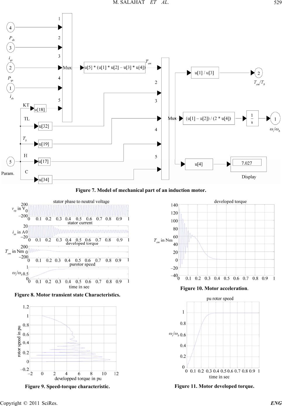 M. SALAHAT ET AL. Copyright © 2011 SciRes. ENG 529 Figure 7. Model of mechanical part of an induction motor. Figure 10. Motor acceleration. Figure 8. Motor transient state Characteristics. Figure 11. Motor de velope d torque. Figure 9. Speed-torque characteristic.  M. SALAHAT ET AL. 530 Figure 12. Motor stator current. eferenced to the stator) from the model. Figure 13 odel can be investigated further by running a va (from 0.32 se (r shows the rotor phase currents. These are particularly instructive, as they clearly show that the frequency of the rotor currents changes with the speed of the machine. At start, the rotor currents have a 60 Hz frequency, but the frequency drops as the motor accelerates, reaching very low frequencies as the motor nears synchronous speed. Of course, once the motor reaches synchronous speed there is no relative motion between the rotor squirrel- cage bars and the rotating magnetic field. Thus the cur- rent in the rotor bars drops to zero as shown in the Fig- ure 13. The m riety of studies with it. As an example, one could vary the load torque and observe the steady-state speed of the machine and determine the effect on the acceleration time. The readings could then be plotted to provide the torque speed curve from zero to full-load as shown in Figure 14 for the above mentioned motor with load torque equal to nominal load (T = 12 N.M.) Starting time increases as load increases c with load torque T = 0 to 0.40 sec when load torque T = Tb). The oscillating torques, however, reach a peak of about 132 N.M. (T/Tb = 11) at t = 0.0107 sec, as in the no-load case. Steady-state speed related to synchronous Figure 13. Motor rotor current. speed drops f es increase of to demon- str 5. General Conclusions this paper, Implementation of a modular Simulink n model built up sys- te rom 1 (T = 0) to 0.95 (T* = 1). Increasing load torque on motor shaft caus torque oscillation which will continue to rotor speed of 0.5 - 0.6 synchronous speed. At the end of transient state torque oscillation will be very small and decreasing with torque increasing and finally disappear. Maximum torque at starting obtained at the same time (not depend- ing on load torque), but speed change behavior is differ- ent for different loads. This maximum value of motor torque at motor starting varies for different load very slightly. As this maximum obtained at starting through very small period (during 1-2 cycles), rotor speed at this period can be considered slightly changed (constant). These statements leads to a result: Maximum torque of an induction motor can be obtained approximately ana- lytically, considering rotor speed is constant. Also, the moment of inertia can be changed ate the effect of starting high inertia loads. As inertia increases torque oscillations (peaks with large values) increase at the beginning of starting process, but speed and torque oscillations near the synchronous speed are less (decrease at the end of starting process). Starting period duration approximately proportional to total iner- tia of drive, as noted in Figure 15. In model for induction squirrel cage motor simulation has been introduced. This model enables the users to access to all the internal variables for getting an insight into the motor operation. It’s available to investigate and predict the transient behavior of the three-phase induction motor using stationary reference frame. Using SIMULINK, the simulatio matically starting from simple sub-models and blocks for the induction motor circuits and components. Figure 14. Motor starting under load. Copyright © 2011 SciRes. ENG 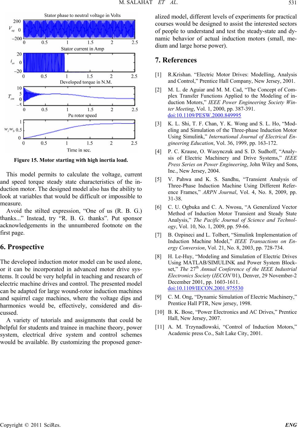 M. SALAHAT ET AL. Copyright © 2011 SciRes. ENG 531 Figure 15. Motor starting with high inertia load. This model permits to calculate the voltage, current an he stilted expression, “One of us (R. B. G.) th he developed induction motor model can be used alo iety of tutorials and assignments that could he . References ] R.Krishan. “Electric Motor Drives: Modelling, Analysis d speed torque steady state characteristics of the in- duction motor. The designed model also has the ability to look at variables that would be difficult or impossible to measure. Avoid t anks...” Instead, try “R. B. G. thanks”. Put sponsor acknowledgements in the unnumbered footnote on the first page. 6. Prospective Tne, or it can be incorporated in advanced motor drive sys- tems. It could be very helpful in teaching and research of electric machine drives and control. The presented model can be adapted for large wound-rotor induction machines and squirrel cage machines, where the voltage dips and harmonics would be, effectively, considered and dis- cussed. A varbe lpful for students and trainee in machine theory, power system, electrical drive system and control schemes would be available. By customizing the proposed gener- alized model, different levels of experiments for practical courses would be designed to assist the interested sectors of people to understand and test the steady-state and dy- namic behavior of actual induction motors (small, me- dium and large horse power). 7 [1 and Control,” Prentice Hall Company, New Jersey, 2001. [2] M. L. de Aguiar and M. M. Cad, “The Concept of Com- plex Transfer Functions Applied to the Modeling of in- duction Motors,” IEEE Power Engineering Society Win- ter Meeting, Vol. 1, 2000, pp. 387-391. doi:10.1109/PESW.2000.849995 [3] g and S. L. Ho, “Mod- naly- andhu, “Transient Analysis of gbuka and C. A. Nwosu, “A Generalized Vector Implementation of ives K. L. Shi, T. F. Chan, Y. K. Won eling and Simulation of the Three-phase Induction Motor Using Simulink,” International Journal of Electrical En- gineering Education, Vol. 36, 1999, pp. 163-172. [4] P. C. Krause, O. Wasynczuk and S. D. Sudhoff, “A sis of Electric Machinery and Drive Systems,” IEEE Press Series on Power Engineering, John Wiley and Sons, Inc., New Jersey, 2004. [5] V. Pahwa and K. S. S Three-Phase Induction Machine Using Different Refer- ence Frames,” ARPN Journal, Vol. 4, No. 8, 2009, pp. 31-38. [6] C. U. O Method of Induction Motor Transient and Steady State Analysis,” The Pacific Journal of Science and Technol- ogy, Vol. 10, No. 1, 2009, pp. 59-66. [7] B. Ozpineci and L. Tolbert, “Simulink Induction Machine Model,” IEEE Transactions on En- ergy Conversion, Vol. 21, No. 8, 2003, pp. 728-734. [8] H. Le-Huy, “Modeling and Simulation of Electric Dr Using MATLAB/SIMULINK and Power System Block- set,” The 27th Annual Conference of the IEEE Industrial Electronics Society (IECON’01), Denver, 29 November-2 December 2001, pp. 1603-1611. doi:10.1109/IECON.2001.975530 [9] f Electric Machinery,” Drives,” Prentice Control of Induction Motors,” C. M. Ong, “Dynamic Simulation o Prentice Hall PTR, New jersey, 1998. [10] B. K. Bose, “Power Electronics and AC Hall, New Jersey, 2007. [11] A. M. Trzynadlowski, “ Academic press Co., Salt Lake City, 2001. |