Engineering
Vol.5 No.10A(2013), Article ID:37392,6 pages DOI:10.4236/eng.2013.510A004
Impact of Geomagnetically Induced Currents Secondary Event on the High-Voltage Synchronous Motors
Institute of Power Engineering and Electrical Engineering, Togliatti State University, Togliatti, Russia
Email: vvvahnina@yandex.ru
Copyright © 2013 Vera V. Vakhnina, Aleksey A. Kuvshinov. This is an open access article distributed under the Creative Commons Attribution License, which permits unrestricted use, distribution, and reproduction in any medium, provided the original work is properly cited.
Received July 30, 2013; revised August 30, 2013; accepted September 7, 2013
Keywords: Geomagnetically Induced Current; Step Down Substation; Power Transformer; Synchronous Motor; High Order Harmonics
ABSTRACT
It is justified that during geomagnetic storms the high voltage synchronous engines are being impacted by high current harmonics of even sequences powered by power transformer due to geo-induced high voltage currents flowed through the windings. Equivalent circuits of step down substation and HV synchronous motors are made for making it possible to consider a saturation of power transformer magnetic system and higher current harmonics availability in stator windings. Analytic expressions for higher current harmonics and extra capacity losses calculation in stator windings are received, as well as the calculation of induction torques allowing to denote a rate of geomagnetic processes impact on synchronous engine operation at various step down substation parameters.
1. Introduction
During geomagnetic storm periods (GMS), the geomagnetically induced currents (GIC) are flowing into highvoltage power grids and high-voltage power transformer windings with dead-earthed neutral, which in turns create asymmetric saturation of magnetic system and multiple increase of nonsinusoidal magnetizing current [1,2]. As a result, power transformer becomes a powerful source of high order current harmonics, which impact on all power consumers of power distribution circuit [3,4]. Electrical motor load is the most sensitive to supply voltage quality degradation, especially high-voltage synchronous motors (SM) with direct connection to power distribution circuit 6 (10) kV. High order currents in stator SM windings result into additional power loss and additional electromagnetic torque constituents appearing.
The most dangerous thing for SM is additional power losses that cause insulation temperature increase, particularly in slot-embedded part of stator windings in the period of GMS. This is a factor of gradual accumulating of defects and accelerated slot-embedded insulation wear, damaging of which could cause up to 80% cases of highvoltage SM stator insulation failures. Nevertheless, the questions of GIC’s impact on work conditions of SM high-voltage are not reflected in science literature. In this relation it is up-to-date and practically significant task to evaluate a level of high order current in stator SM windings during GMS period.
2. Equivalent Circuit for Step Down Transformer Substation
Assigned task is solved based on typical step down substation of industrial enterprise, main consumers of which are SMs of turbine-driven air compressor connected to sections I c - II с of switch-yard bus SY-6kV (Figure 1(a)).
Figure 1(a) shows only those components of step down substation which are required to be considered while creating the estimated equivalent circuit needed for SM work conditions study by magnetizing of T1 power transformer with low voltage split winding (LV1 and LV2) by means of geo-induced current that flows in phase wires of electric power lines PL-110 kV during GMS period. Complete equivalent circuit of step down substation, which magnetizing contour of T1 power transformer is taken into account by harmonic source entry of magnetizing current,  is shown on Figure 1(b).
Equivalent circuit has the following designations accepted:
 (a)
(a)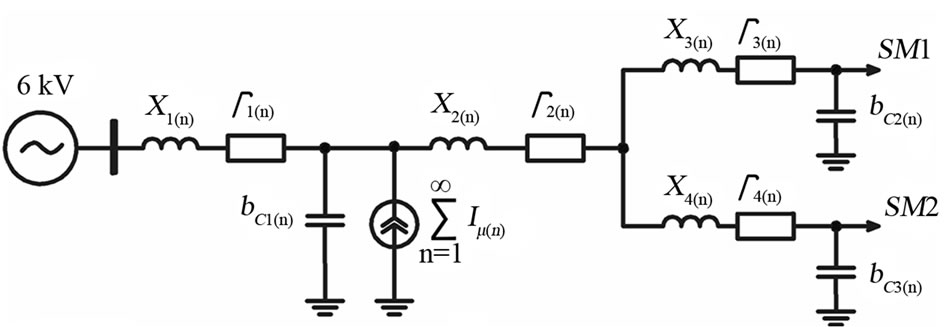 (b)
(b)
Figure 1. Simplified electric scheme (a) and equivalent circuit (substitution scheme) (b) of the step down transformer substation.
 —inductive and active resistances, and also capacitive conductance of phase wire PL-110 on n-harmonic frequency;
 —inductive and active resistances of phase winding of high-voltage (HV) T1 power transformer on n-harmonic frequency;
 —inductive and active resistances on n-harmonic frequency of T1 power transformer LV1 phase winding and cable line CL-6 feeding SM1 from section I c ;
 —inductive and active resistances on n-harmonic frequency of T1 power transformer LV2 phase winding and cable line CL-6 feeding SM1 from section II c ;
 —capacitive conductances on n-harmonic frequency of cable lines CL-6 feeding SM1 and SM2 correspondingly;
 —n-harmonic of Т1 power transformer’s magnetizing current.
Magnetization current’s harmonics parameters  for equivalent circuit Figure 1(b) are defined per computer simulation of T1 power transformer of TRDN- 63000/115/6.3/6.3 type, under conditions of flowing through HV geo-induced currents windings of value 82.64 A, that complies with Geomagnetic Field Disturbance indexes K-8; K-9. Calculation results are shown on Figure 2.
As it is shown on Figure 2(a) magnetizing current of T1 power transformer under conditions of GIC contains full spectrum harmonics, the most important of which are harmonics indexes up to n = 8 inclusively. It should be noted that presence of even harmonics of magnetizing current 
 and
and 
 , value of which is quite comparable with main magnetizing current’s harmonic
 . Rms value of magnetizing current
 , i.e. multiply increases the nominal value of no-load current (0.254%) of power transformer without GIC, and rms value of only even harmonics of magnetizing current equals to
  . The last statement serves to show that nature of remagnetizing of T1 power transformer magnet system is close to single wave detection condition of magnetizing current.
3. Equivalent Circuit of Synchronous Motor for High Order Harmonics
Due to magnetic and rotor electric asymmetry, conditioned by excitating winding, SM equivalent circuits on longitudinal and transversal axes are different as it is shown on Figure 3 [5]. An actual three-phase stator winding is presented on equivalent circuit by system of two orthogonal rotating loops (contours)—longitudinal and transversal, and rotor—by excitating winding contour, longitudinal and transversal damping contours.
High order harmonic currents are starting to flow when saturating of T1 power transformer under GIC impact in SM stator windings except basic current constituent with 50 Hz frequency. If saturation isn’t taken into account, SM is allowed to be considered as line system for which superposition principle being applicable. In this case analysis is hold independently for basic constituent and for each high order harmonic. Among other things, the consumed current and SM electromagnetic torque are defined by amount of constituent currents and torques from each harmonic. SM equivalent circuit parameters:
 —active and inductive resistances of stator winding dissipation on n-harmonic frequency;
 —mutual induction resistance between stator and rotor windings on longitudinal and transversal axes on n-harmonic frequency;
 —active and inductive resistances of excitating winding dissipation on n-harmonic frequency;
 —inductive dissipation resistances of longitudinal and transversal damping contours on n-harmonic frequency;
 —active resistances of longitudinal and transversal damping contours on n-harmonic frequency.
The method stated in [5] allows to define equivalent circuit parameters, but it is required to take into account additional features:
1) An increase of all inductive resistances on n times comparing to values on basic harmonic frequency;
2) n-harmonic’s slipping (s(n)) of magnetomotive force

Figure 2. Line spectrums of magnetization current’s harmonic constituents of T1 power transformer type TRDN-63000/ 115/6.3/6.3 under conditions of flowing through HV geo-induced currents of value 82.64 A.
 (a)
(a) (b)
(b)
Figure 3. SM equivalent circuit for high order harmonics on longitudinal (a) and transversal (b) axes.
(mmf) of direct and reverse sequence created by n-harmonic of stator winding phase currents, value of which is defined when rotor synchronous motion saving by following expression
 (1)
(1)
where s—rotor slipping relatively to rotating magnet field of basic harmonic (during synchronous rotor motion at s = 0). Upper sign corresponds to stator winding current harmonics of direct sequence; lower sign corresponds to stator winding current harmonics of reverse sequence: an increase of active stator and rotor resistances due to skin-effect on higher frequencies. Dependence of active SM contours resistances on frequency is being approximated by empirical expression [6]
 (2)
(2)
where —contour resistance on basic harmonic frequency.
4. Synchronous Motor Complex Resistance on n-Harmonic Frequency
In order to evaluate the individual harmonics impact rate, it is advisable to determine an average equivalent and complex SM resistance on two axes [7], which regarding to equivalent circuit of n-harmonic frequency (see Figure 2) is defined by the following expression
 (3)
(3)
where —complex conductances of mutual induction between stator winding and rotor contours on longitudinal and transversal axes on n-harmonic frequency;
 —complex excitating winding conductance on n-harmonic frequency;
 —complex longitudinal and transversal damping contours conductances on n-harmonic frequency correspondingly.
Expression (3) can be folded and written in a from that is more convenient and compact for its further use
 (4)
(4)
where

 —are average equivalent active and reactive SM resistances on two axes;
 —summary active resistances of parallel branches of SM equivalent circuit on n-harmonic frequency on longitudinal and transversal axes correspondingly;
 —summary reactive resistances of SM equivalent circuit’s parallel branches on longitudinal and transversal axes correspondingly.
On the basis of (4) the SM equivalent circuit for high order harmonics (see Figure 2) can be set to complex resistance 
5. High Order Current Harmonics in Synchronous Motor Stator Windings
In order to define high order harmonic currents that flow into stator SM windings during GIC power transformer magnetic biasing, it is required to complement complex resistance of SM equivalent circuit to step down substation equivalent circuit showed on Figure 1(b) 
It is advisable to have current source preliminarily being transformed  into equivalent EMF source
 , the internal complex resistance of which is defined by the following expressions
 (5)
(5)
As follows from the integration, the estimated equivalent circuit (see Figure 4) is received and allows to conduct current distribution analysis of high order harmonics generated by transformer magnetizing contour, and possible resonance phenomena as well. Estimated equivalent circuit does not consider winding active resistances of power transformer.

Figure 4. Estimated equivalent circuit for defining of n-harmonic current in SM stator winding.
From the condition
 (6)
(6)
resonance frequency of internal complex resistance wp is defined
 (7)
(7)
where w(1)—is angular frequency of basic harmonic; —wave resistance PL-110 kV.
It should be noted that n = 20 harmonic is resonance for stepdown substation showed on Figure 1 and the maximum value of which is compliant with EMF Em(20) = 86.14 В.
Using equivalent circuit on Figure 4 it is possible to write n-harmonic current that flows in SM stator winding as
 (8)
(8)
where KHV-LV—complex division ratio of magnetizing current’s n-harmonic between HV and LV sides; KLV1-LV2 —complex division ratio of magnetizing current’s n-harmonic between split LV windings; KD—complex division ratio of magnetizing current’s n-harmonic between SM and longitudinal capacitive conductance of power cable.
Expression (8) graphically shows which part of n-harmonic of T1 power transformer magnetizing current flows in SM stator winding and how it depends on step down substation parameters. Values of complex division ratios are defined by following expressions
 (9)
(9)
where 
 —complex SM resistances on n-harmonic frequency taking power cable parameters into account.
As per (8) and (9) it is possible to define high order harmonics in SM stator windings connected to bus sections I с (ISM(n)I) and II с (ISM(n)II), during GIC impacting on T1 power transformer from power grid side. Quantitative estimations made for synchronous turbomotors of STM series with 10 MW capacity allow to admit that majority level of high order harmonics in stator windings do not exceed (3 ÷ 7)% from same-name level harmonics of T1 power transformer magnetizing current. It’s only for 19th, 20th and 22nd harmonics that relative level is significantly higher and reaches the values of 19%, 48% and 13.2% correspondingly. Although in same-name units the indicated harmonics are not exceeding 2nd current harmonic level in SM stator windings.
The most serious effects for SM could arise providing that bC1 » 0 and high order harmonics of magnetizing current will “flow down” on T1 power transformer LV side, and SM power is carried out only from one bus section.
 (10)
(10)
Finally magnetizing current’s high order harmonics of T1 power transformer will practically be flowing through SM stator windings, i.e. ISM(n) @ I(n) In this case additional capacity losses that occurred in SM due to high order current’s harmonics, at values set in Figure 2, will increase capacity losses in ≈ 1.43 times in nominal condition.
6. Synchronous Motor Asynchronous Moments
At ISM(n) @ Iμ(n) a necessity is also arisen to take into account magnetizing current of asynchronous electromagnetic torque constituents created by high order harmonics.
Permanent asynchronous moment on SM shaft, conditioned by interaction of same magnetic flux harmonics in air gap and rotor current, is made up of two constituents [5]
 (11)
(11)
where —is asynchronous torque, conditioned by excitating winding reaction and longitudinal damping contour;
 —asynchronous torque conditioned by longitudinal damping contour.
In order to use the last formula it is necessary to know the n-harmonic currents values in separate SM contours. It is notably inconvenient for practical calculations carrying out. In this regard it is advisable to refer to simplified SM equivalent circuit with equivalent complex resistance. For such a scheme it is possible to write down
 (12)
(12)
where р—is poles pairs number; m—number of SM stator windings phases.
Taking slipping  into account regarding (1) and SM n-harmonic current values as per (8) and (9) for synchronous rotor motion (s = 0) the expression (12) is reduced to form
 (13)
(13)
For instance, for the most significant 2nd harmonic of T1 power transformer magnetizing current and unfavorable conditions combination, when КHV-LV = 1, КLV1-LV2 = 1 and КD = 1, the relative value of asynchronous torque is equal to approx.  This value of asynchronous torque is capable to affect to rotor mechanical movement and disturb stable SM operation in case of nominal load on shaft under low power voltage conditions.
7. Conclusion
For the first time the existence of indirect impact of geoinduced currents on high voltage synchronous engines operation within geomagnetic storms is justified. Danger level of geomagnetic activity against synchronous engines is defined by higher current harmonics level of even sequences occurred in stator windings which is significantly lower in the case when step down substation power supply is delivered from electrical transmission line having cable plants.
REFERENCES
- J. G. Kappenman, “Geomagnetic Storms and Their Impact on the U.S. Power Grid,” Metatech Corporation, Goleta, 2010, 197p.
- M. Lahtinen and J. Elovaara, “GIC Occurrences and GIC Tests for 400 kV System Transformer,” IEEE Transactions on Power Delivery, Vol. 17, No. 2, 2002, pp. 555- 561. http://dx.doi.org/10.1109/61.997938
- V. V. Vakhnina, A. N. Chernenko and V. A. Kuznetsov, “Effects of Geomagnetically Induced Currents on Power Transformers and Power Systems Magnet System Saturation,” Science Vector of Togliatti State University, Vol. 21, No. 3, 2012, pp. 65-69.
- V. V. Vakhnina, A. A. Kuvshinov and N. A. Len, “Synchronous Generator’s Static Stability Analysis in Consideration of Current’s High Order Harmonics in Stator Circuit,” Journal of Higher Education Institutions, Electromechanics, No. 3, 2012, pp. 51- 59.
- S. I. Gamazin, V. A. Stavtsev and S. A. Tsyruk, “Transient Phenomena in Industrial Power Supply Systems Conditioned by Electromotive Loading,” MEI Publications Ltd., Nicosia, 1997, 424p.
- I. V. Zhezhelenko, “High Order Harmonics in Power Supply Systems of Industrial Enterprises,” 5th Edition, Energoatomizdat, 2004, 358p.
- A. V. Ivanov-Smolenskiy, “Electric Machines: Guide Book for IHEs. In 2 Tomes,” 3rd Edition, MEI Publications Ltd., Nicosia, 2006, 532p.