Journal of Modern Physics
Vol. 2 No. 2 (2011) , Article ID: 4368 , 7 pages DOI:10.4236/jmp.2011.22012
Self-Sensing and –Actuating Probes for Tapping Mode AFM Measurements of Soft Polymers at a Wide Range of Temperatures
1Graz Centre for Electron Microscopy (ZFE), Graz, Austria
2Nano Scan Technology Co., Dolgoprudny, Russia
3Shumakov Federal Research Center for Transplantology and Artificial Organs, Moscow, Russia
4National Technical University of Ukraine (KPI), Kiev, Ukraine
5Institute for Electron Microscopy (FELMI), Graz University of Technology, Graz, Austria
E-mail: nadejda.matsko@felmi-zfe.at
Received October 9, 2010; revised November 13, 2010; accepted November 16, 2010
Keywords: Tuning Fork, Sharp Tungsten Tip, AFM, Tapping Mode, Soft Materials
ABSTRACT
Self-sensing and –actuating probes optimized for conventional tapping mode atomic force microscopy (AFM) are described. 32-kHz quartz tuning forks with a chemically etched and focus ion beam (FIB) sharpened (curvature radii are 5-10 nm) tungsten tip are stable at air and liquid nitrogen atmosphere and at a wide range of temperatures. If driven at constant frequency, the scan speed of such sensors can be up to 3 Hz. AFM was performed on polymer samples in order to study the stability and applicability of these sensor for investigation of soft materials with high dynamical tendencies.
1. Introduction
After being introduced as the analogue of STM for the high-resolution profiling of nonconducting surfaces, AFM has developed into a multifunctional technique suitable for characterization of topographical, mechanical, adhesive, friction and hydrophilic/hydrophobic properties of a practically unlimited range of materials [1,2]. Very high spatial resolution can be achieved regularly on hard surfaces. In particular, atomic resolution on flat surfaces of hard materials has been demonstrated in ultra high vacuum (UHV) during the last 10 years [3]. Although the observation of periodic lattices showing atomic and molecular order on hard sample surface attracts the great interest of many research groups, current AFM application is much broader and includes investigations of soft materials such as polymers and biological objects using different environmental and thermal conditions.
In conventional AFM the optical detection system where a laser beam is reflected from the backside of the cantilever, is used for measurements of its deflection. In cases where the sample itself is sensitive to light (photosensitive materials) or local heating caused by it (very soft polymers) a non-optical detection method is required [4]. Non-optical detection method is also the only choice for the proper AFM investigation in cryo conditions because of not proper performance of semiconductor optical devices at low temperatures. Usage of piezoelectric quartz tuning forks with the tip, which is mounted perpendicular (tapping mode) or parallel (shear force mode) to the tuning fork prong, have been employed as an alternative to the conventional optical sensing method in AFM [5]. The electrode patterns for oscillating the tuning fork are formed on four sides of the beam structure and the tuning fork is vertically vibrated to the sample surface by exploiting the piezoelectric property of crystal quartz [6]. The detection of such oscillation is done electrically and no additional laser system is required.
The other advantages of these piezoelectric sensors are its high quality factor (Q), which considerably increases the sensitivity of the AFM system and allows one to make true atomic resolution lateral force microscopy in UHV [5]. However, the high Q factor has a serious drawback. If driven at constant frequency, the high Q-values of tuning forks lead to a very slow response of the oscillation amplitude or phase on a steplike change in the tip-sample interaction on a time scale Q/f0. The resulting limitation is a very low scan speed [4]. For the sample with high dynamical tendencies and at non stable environmental conditions (air or cold gas flow) slow imaging is crucial because sample structure changes much faster than the microscope can detect. A significant increase in scan velocity can be achieved with the use of a phase-locked loop (PLL) instead of conventional z-feedback loop scheme [7-9]. However, for the proper setup of PLL high quality factor Q (> 10000) of the tuning fork is required. The latter regularly can be achieved in UHV. In air or cryo condition the quality factor is usually significantly lower. That causes a high noise level during scanning using frequency modulation SPM mode. The usage of PLL also requires an additional equipment and a specially designed setup.
Another critical point in adapting tuning forks for atomic force microscopy is the probing tip. Several strategies for fabrication of such a probe have already been reported. The main two of them are based on: 1) electrochemical etching of W, Ni or Pt/Ir wires [7,10,11], and 2) sharpening of the wire by focused ion beam milling [12]. The curvature radii of such probes usually vary from 50 till 20 nm, which is still worse than standards for conventional Si cantilevers (30-10 nm).
In this article we propose new sensors which are based on commercially available 32-kHz quartz tuning forks. The W wires which are initially glued to the one prong of tuning fork by epoxy, afterwards are sharpened by a two step technique based on electrochemical etching using 3M KOH till the obtained curvature radii are less than 20 nm (first step) followed by gentle FIB milling (second step). Such a procedure guarantees the final tip radii in a range of 5-10 nm. The variation of the needle length on the tuning fork with the W needle system allows one to adjust a Q factor till 400-1000 and as a consequence the fast scanning speed up to 3 Hz is possible. The test measurements have been performed on a microtomy prepared surface of the polyamide 6/acrylonitrilebutadiene-styrene (PA6/ABS) copolymer bulk under environmental condition. No vibroisolation has been used. Because of high spring constant of tuning fork-W needle sensors the scanning parameters have to be adjusted such that the scanning gets performed in almost non contact regime, otherwise the polymer surface gets destroyed by the W needle. Our sensors are suited for fast scan application and stable in non friendly environment condition (air, cold gas flow).
2. Methods
For the preparation of the sensors (Figure 1(c)) a three

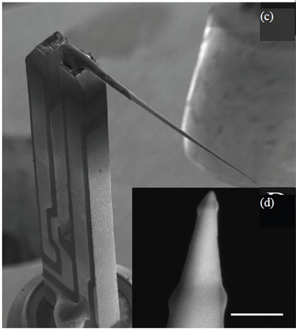
Figure 1. Scanning electron micrograph of the sensors. (a) W needle tip after chemical etching; (b) the tip having been Gallium beam irradiated; (c) final shape of the UFS sensor; (d) the contamination layers on the top of the needle and in the lower zone where stigmatism correction and focusing procedure took place. Scale bars are 100 nm.
step procedure was used:
First step: A 100 µm thick W wire was attached to the top of one prong of a commercially available 32-kHZ tuning fork. For this a 2-3 mm piece of the wire was first attached to the quartz using rapidly polymerized silver paste and than stabilized by epoxy. Fast bonding using silver past significantly simplifies the procedure of fixing the needle in the required position. However, the silver paste is weak glue and it usually does not hold the needle during chemical etching. Therefore additional epoxy fixation is essential.
Second step: The W needle was electrochemically etched in 3M KOH solution. Etching procedure has been performed at 3-10 V bias voltage and 2 mA stop current. The steel cup has been filled well up with the electrolyte solution. The tuning fork with the attached needle has been clipped onto the holder and set on positive and the solution on negative bias. The needle has been dipped into the solution and etched till the amount of bubbles you see have been almost diminished. Once the tip was etched, it has been washed in nanopure H2O. The obtained tuning fork-W needle system afterwards was analyzed using high resolution SEM in order to select needles with the curvature radii less than 20 nm (Figure 1 (a)).
Is also worth to note high aspect ratio of the needles produced by this procedure? Half cone angle of such tips is considerably less than 10 ° what can also be the crucial advantage for a number of applications.
Third step: Gentle milling of the obtained needles using FIB. The sensors were mounted to the holder in such way that the tip of the needle was oriented strictly parallel to the ion beam. The milling procedure was performed first at 30 kV (50 pA) and finally polished at 5 kV (10 pA) in order to minimize the amorphous layer on the surface of the tip (Figure 1 (b)).
The final control of the curvature radii of the tip using HR SEM is not recommended because of the carbon contamination issue during SEM scanning. Carbon and some residual components which are present in every SEM column are immediately adsorbed on the needle surface and make the curvature radii of the tip bigger (Figure 1 (d)). If the observation of the needle is strictly necessary, after making SEM image the sensors have to be O2 etched at least for 5-10 min.
3. Results and Discussion
The goal of this study was to find an optimal condition for the usage of a tuning fork based sensors for the amplitude modulation AFM mode scanning in air and later in cryo environment. To reach this goal a specially designed stand for testing tuning forks has been constructed. We use a piezotube-based scan head with a sample scanning scheme. In such scheme the 40 µm range scanner is placed coaxially to the probe holder. Both, probe holder and piezotube, are implemented on the heavy metal platform. The coarse tip-sample approach can be archived using a step-motor moving the piezotube with the sample towards or backward the tuning fork sensor mounted in a probe holder. In order to minimize the mechanical noise and drift of different origins (mechanical, acoustical etc.), the mechanical contact between step-motor and scanner was disconnected after approach. All AFM images and resonance characteristics were acquired using an EG-3000M SPM controller and Nspec Universal software produced by Nano Scan Technology Ltd. For the cryo experiments the AFM stand was operated in a liquid nitrogen vapor chamber with controlled temperature.
Figure 2 represents typical resonance curves for the
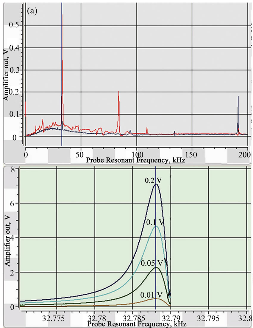
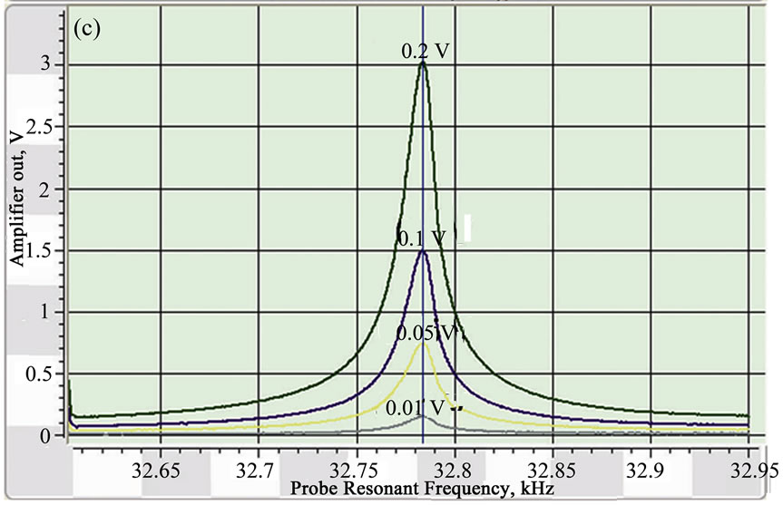
Figure 2. Image (a) shows typical resonance curves for a tuning fork in vacuum (blue curve), and in ambient condition (red curve). Resonance frequency of the tuning fork at different oscillation amplitudes are represented in vacuum (b) and in air (c).
closed (high vacuum condition) and open (ambient condition) tuning forks at room temperature.
Driving AC voltage for these measurements has been adjusted to 0.1V and kept constant. The comparison shows the well-established difference in resonance characteristic for the tuning fork when it oscillates in air and in vacuum. The Q factor value is significantly increased in vacuum (Qvac 10007, Qair 3152), as well as the noise value is significantly increased in air. If the oscillation amplitude is kept lower than 0.1 V, the output signal has to be gained by a variable gain lock-in amplifier. For the closed tuning fork this requirement is not critical as the signal-to-noise ratio in HV is relatively low, but when measurements have to be done in air, and especially in cryo condition (cold gas flow), the noise values, which are also gained proportionally, make the advantage of the high sensitivity of the tuning fork compared to conventional cantilever almost negligible. Taking all this into consideration, the series of experiments with bonding of the different types of tips onto the tuning fork were performed in order to obtain the tuning fork based sensor which will:
a) be at least as sharp as conventional Si cantilevers (curvature radii of the tip should be less than 10 nm);
b) have stable frequency characteristics in air;
c) have a high output signal with a wide range of the oscillation amplitude values;
d) allow one to perform fast scanning in tapping mode AFM
3.1. Preparation of the Sharp Tips
The achievable localization or spatial resolution for both, analytical (topographical and phase study) and fabrication process (polymer formation and modification), strongly depends on the sharpness and aspect ratio of the tip. There are three general concepts for preparation of the tuning fork based sensors. First one is based on bonding a standard microfabricated cantilever with sharp tips to the one or both tuning fork prongs [13-15]. Fabrication of a probe with the tuning fork structure that is integrated with the tip by using quartz micromachining technology and FIB system is the second concept [6]. The third approach is electrochemical or FIB sharpening of the metal wire which afterwards is mounted to the tuning fork prong [7,10-12]. The main requirement of the first two approaches is to obtain a self-sensing and –actuating sensor with high Q factor and high sensitivity for the UHV non-contact SPM applications. For the fast scan applications using tapping mode AFM in air and/or cryo condition they can hardly be applied because of the high Q factor (which restricts the velocity of scanning) and noise issue. Therefore attachment of the sharp metal wire or alternatively the sharpening of the wire already attached to the tuning fork prong is the most perspective way of tuning fork sensor fabrication.
3.2. Resonance Characteristics of the Sensors
Figure 3 represents the typical resonance characteristics of the tuning fork based sensors described above. The frequency curves demonstrate very high stability at the amplitude range from 0.01-1 V. In the working range of 0.1-1 V both, first and second resonance could be used for the measurements.
The resonance frequency and Q factor of the piezoelectric sensors depend on the attached mass value and damping level. The longer the attached needle, the lower is the intrinsic resonance frequency and the smaller is the Q factor. Therefore the variation of the needle length
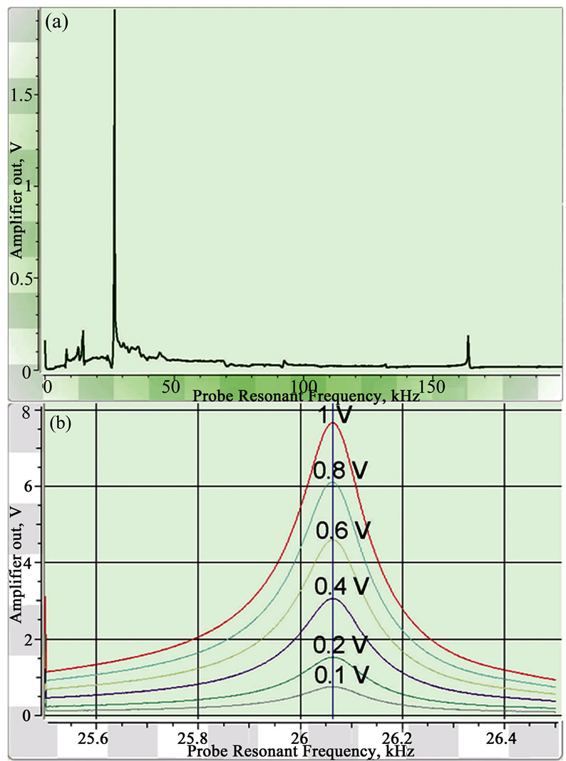

Figure 3. (a) Single resonance curve in the range of 0-200 kHz. Resonance curves of the sensor at the different oscillation amplitudes are shown for the 1st resonance (b) and the 2nd resonance (c).
allows one to adjust the Q factor according to the requirements of the experiments, which have to be done. Figure 4 represents the resonance peaks shift for the tuning forks with the 1 mm and 2.2 mm needles.
For the sensor with 1 mm needle Q factor is 742 and for the sensor with 2.2 mm needle it is 580. The actual range of the Q factor which we have observed during sensor study is from 400 till 1000. Therefore taking into consideration the fact that the sensor demonstrates very high stability and high output signal at a wide range of the oscillation amplitudes, it is possible to assume that the sensors could be the analogue of the piezoresistive cantilevers which are quite simple in use and do not require any additional equipment like PLL setup.
For investigation of temperature behavior of quartz tuning fork probes, the resonance curves of the tuning


Figure 4. The dependence of the Q factor value on the length of the W needle which is attached to one prong of the tuning fork.
fork with a glued 50 µm tungsten wire was measured at different temperatures in a liquid nitrogen vapor chamber with the controlled temperature.
The temperature was changed in 20 °C steps from 20 °C to -120 °C. Resonance curves for some temperatures and dependence of resonance frequency f0 with the temperature are shown in Figure 5. Resulting measurements show stable resonances for all used temperature ranges with a monotonic decrease of the resonance frequency f0 with temperature. The measured oscillation amplitude is also generally increasing with the cooling.
This dependence correlates with the behavior of viscosity of nitrogen with temperature which is increasing with temperature from a value of µ = 0.01 cP at -120 °C up to µ = 0.0175 cP at 20 °C. So we can propose that decreased viscous friction of the tungsten wire in gas atmosphere at lower temperatures leads to lower damping and therefore higher resonance frequency and oscillating amplitude. Nevertheless the resonance parameters of the sensors for investigated temperatures stay in the suitable range for the AFM measurements.
3.3. Tapping Mode AFM Study of Soft Materials with High Dynamical Tendencies Using Quartz Tuning Fork Probes
The high sensitivity of polymer samples towards sample
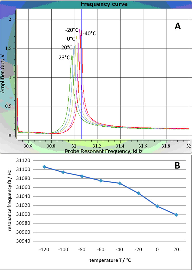
Figure 5. (a) Resonance curves of the sensor at the different temperatures. (b) Dependence of the resonance frequency on the temperature.
preparation procedure [16] as well as towards microscopy measurement conditions makes the determination of their original structure especially challenging and requires appropriate methodological approaches. In order to minimize additional complications coming from the possible instability of the piezosensor during AFM investigation of soft materials at cryo condition (The main goal of the study will be published elsewhere.) we have tested our sensors on the soft PA6/ABS copolymer which on the one hand has a very sensitive block face surface structure, and on the other hand has a strong tendency to the mechanical drift (mostly because of ABS phase) [17]. All measurements were performed in the ambient condition. The scanning area was open and no additional vibroisolation has been used. Figure 6 represents the phase image which has been obtained using quartz tuning fork probes (Q factor 708, resonance frequency 26,78 kHz).
Oscillation amplitude was kept at 0.1 V, the output signal was 1.1 V. Zone (1) in the Figure 6 corresponds to the area which first was scanned with the Set point values 0.6-0.8 V. The polymer surface got completely destroyed. The area 2 in the Figure 6 was scanned first with the Set point value 0.9 V, and final image was obtained when the Set point value has been adjusted so that

Figure 6. AFM tapping mode phase image obtained from the freshly prepared block face surface of the PA6/ABS copolymer at ambient condition. Measurement parameters for the region 1 are: A0 1.1 V, Asp 0.6-0.8 V; region 2: A0 1.1 V, Asp 0.9 V. Scan speed is 2 Hz. No additional image processing (flatten, plane subtraction etc) has been used. Phase variation is 0-20 °.
the scanning was performed in almost non-contact regime. Only latter condition allows one to obtain the tapping mode phase image without structural modification of the sample surface. It should be noted that such sensor as well as all sensors based on the tuning fork usually have very high stiffness which is two orders higher than the spring constant range of conventional cantilevers. For soft polymers it has a great advantage as the tuning fork based sensors can not easily pull into the adsorption layer on the sample surface and also can not stuck to the sample even if the tip was protrude inside the sample bulk during previous tip-sample contact. The disadvantage of the hard sensor is also obvious: it easily may change the sample surface if the landing and scanning parameters were chosen wrong. Another complication is that an almost non contact regime could be very unstable especially with samples which are drifting and therefore the scan speed becomes critical. For example it was not possible to obtain a reasonable phase image of PA6/ABS surface using tuning fork based sensors when the scan speed has been adjusted lower than 0.2 Hz. The working range of the scanning speed for the quartz tuning fork probes is 0.2-3 Hz. In this range the obtained images are stable and the RMS value of 0,01-0,03 V is reasonable for AFM system without active vibroisolation and the closing of the scanning area.
4. Conclusions
As a conclusion, presented sensors can have a great area of application for the soft as well as hard surfaces investigation in air and under cryo condition because of: 1) piezoelectric nature of the tuning fork itself which allows one to avoid optical detection scheme, 2) very sharp tip that guarantees high lateral resolution, 3) stable frequency characteristic and high output signal which make it easy to use, 4) possibility to scan with high speed that is important for the samples with high tendency to drift and for the samples which have fast dynamical changes (phase transition, molecular transport etc).
5. Acknowledgements
We thank Manfred Leisch and Harald Plank for the useful discussion and gratefully acknowledge finical support of the FFG Foundation.
REFERENCES
- G. Binnig, C. F. Quate and C. Gerber, “Atomic Force Microscope,” Physical Review Letters, Vol. 56, No. 9, 1986, pp. 930-933. doi:10.1103/PhysRevLett.56.930
- S. Magonov and D. H. Reneker, “Characterization of Polymer Surfaces with Atomic Force Microscopy,” Annual Review of Materials Science, Vol. 27, 1997, pp. 175-222. doi:10.1146/annurev.matsci.27.1.175
- F. J. Giessibl, “Atomic Resolution of the Silicon (111)- (7x7) Surface by Atomic Force Microscopy,” Science, Vol. 267, 1995, pp. 68-72. doi:10.1126/science.267.5194.68
- J. Rychen, T. Ihn, P. Studerus, A. Herrmann and K. Ensslin, “A Low-Temperature Dynamic Mode Scanning Force Microscope Operating in High Magnetic Fields,” Review of Scientific Instruments, Vol. 70, No. 6, 1999, pp. 2765-2770. doi:10.1063/1.1149842
- T. R. Albrecht, P. Gruetter, P.D. Horne and D. J. Rugar, “Frequency Modulation Detection Using High-Q Cantilevers for Enhanced Force Microscope Sensitivity,” Journal of Applied Physics, Vol. 69, No. 2, 1991, pp. 668-673. doi:10.1063/1.347347
- H. Hida, M. Shikida, K. Fukuzawa, A. Ono, K. Sato, K. Asaumi, Y. Iriye, D. Cheng and K. Sato, “Fabrication of a Quartz Tuning-Fork Probe with a Sharp Tip for AFM Systems,” Sensors and Actuators A: Physical, Vol. 148, No. 1, 2008, pp. 311-318. doi:10.1016/j.sna.2008.08.021
- H. Edwards, L. Taylor, W. Duncan and A. J. Melmed, “Fast, High-Resolution Atomic Force Microscopy Using a Quartz Tuning Fork as Actuator and Sensor,” Journal of Applied Physics, Vol. 82, No. 3, 1997, pp. 980-985. doi:10.1063/1.365936
- W. A. Atia and C. C. Davis, “A Phase-Locked Shear-Force Microscope for Distance Regulation in Near-Field Optical Microscopy,” Applied Physics Letters, Vol. 70, No. 4, 1997, pp. 405-407. doi:10.1063/1.118318
- O.Pfeiffer, R. Bennewitz, A. Baratoff, E. Meyer and E. Gruetter, “Lateral-Force Measurements in Dynamic Force Microscopy,” Physical Review B, Vol. 65, 2002, pp. 161403 (R). doi:10.1103/PhysRevB.65.161403
- M. Todorovic, S. J. Schultz, “Miniature High-Sensitivity Quartz Tuning Fork Alternating Gradient Magnetometry,” Journal of Applied Physics, Vol. 83, 1998, pp. 6229- 6231. doi:10.1063/1.367642
- F. J. Giessibl, “Atomic Resolution on Si(111)-(7×7) by Noncontact Atomic Force Microscopy with a Force Sensor Based on a Quartz Tuning Fork,” Applied Physics Letters, Vol. 76, 2000, pp. 1470-1473. doi:10.1063/1.126067
- L. Zhu, J. Atesang, P. Dudek, M. Hecker, J. Rinderknecht, Y. Ritz, H. Geisler, U. Herr, R. Geer and E. Zschech, “Experimental Challenges for Approaching Local Strain Determination in Silicon by Nano-Raman Spectroscopy,” Materials Science-Poland. Vol. 25, No. 1, 2007, pp. 19- 31. doi:10.1063/1.124780
- W. H. J Rensen, N. F. Van Hulst, A. G. T. Ruiter and P. E. West, “Atomic Steps with Tuning-Fork-Based Noncontact Atomic Force Microscopy,” Applied Physics Letters, Vol. 75, No. 11, 1999, pp. 1640-1642.
- H. Goettlich, R.W. Stark, J. D. Pedarnig and W. Heckl, “Noncontact Scanning Force Microscopy Based on a Modified Tuning Fork Sensor,” Review of Scientific Instruments, Vol. 71, No. 8, 2000, pp. 3104-3107. doi:10.1063/1.1304881
- D. V. Serebriakov, A. P. Cherkun, B. A. Loginov and V. S. Letokhov, “A Scanner for an Ultrahigh-Vacuum Low-Temperature Scanning Tunneling Microscope,”.review of scientific Instruments, 73, 2002, pp. 1795-1801.
- L. C. Sawyer and D. T. Grubb, “Polymer Microscopy,” 2nd edition, Chapman & Hall, New York, 1996.
- C. Sailer, and U. A. Handge, “Reactive Blending of Polyamide 6 and Styrene−Acrylonitrile Copolymer: Influence of Blend Composition and Compatibilizer Concentration on Morphology and Rheology,” Macromolecules, Vol. 40, No. 6, 2007, pp. 2019-2028. doi:10.1021/ma062705c