World Journal of Condensed Matter Physics
Vol.3 No.1(2013), Article ID:28286,7 pages DOI:10.4236/wjcmp.2013.31004
Giant Magnetoimpedance of Cube/Feconi Electroplated Wires: Focus on Angular Sensoric
![]()
1Department of Electricity and Electronics, University of the Basque Country UPV-EHU, Campus of Leioa, Leioa, Spain; 2Department of Magnetism and Magnetic Nanomaterials, Ural Federal University, Ekaterinburg, Russia; 3Department of Physics, Kasetsart University, Bangkok, Thailand; 4Department of Physics, University of Oviedo, Oviedo, Spain.
Email: *galina@we.lc.ehu.es
Received November 5th, 2012; revised December 15th, 2012; accepted December 26th, 2012
Keywords: Giant Magnetoimpedance; Magnetization Process; Magnetic Anisotropy; Magnetic Field Sensors
ABSTRACT
Giant magnetoimpedance effect (GMI) is a subject of special interest proved by applied electrodynamic and technological applications. GMI effect in ferromagnetic tubes is connected with the high sensitivity of the magnetic system to a circular magnetic field near the spin-reorientation magnetic phase transitions offering high sensitivity with respect to an external magnetic field. In this work the non-magnetic CuBe wires were covered by Fe20Co6Ni74 layers by electrodeposition. The thickness of 1 μm for magnetic layer was high enough in order to ensure the high GMI value. Longitudinal magnetic anisotropy was induced by post preparation annealing in a magnetic field of 160 A/m at 320˚C during 1 hour in order to obtain appropriate magnetisation process. Angular dependencies of GMI were measured in a frequency range of 1 to 10 MHz for driving currents of 2.5 to 20 mA. High longitudinal GMI of the order of 400% was observed at quite low frequency of 1 MHz. The highest value of the sensitivity of 520%/Oe was found for the active resistance: Linear sensitivities of 0.023 Ω/˚ and 0.05 Ω/˚ were observed for reasonably low fields of 240 and 275 A/m respectively for small angles, where planar GMI elements are less effective.
1. Introduction
Magnetic materials showing giant magnetoimpedance effect (GMI) are a subject of increasing interest because of fundamental applied electrodynamic interest and focus on technological and biomedical applications [1-3]. There were many studies of ferromagnetic resonance and GMI effects in electroplated wires [4,5]. It is established that high GMI value connected with the high sensitivity of the magnetic system to a circular magnetic field near the spin-reorientation magnetic phase transitions [6,7]. The magnetoimpedance phenomenon consists of the change of the total impedance, Z, and its real (R) and imaginary (X) parts of a ferromagnetic conductor under the application of an external magnetic field (H) when high frequency (f) alternating current flows through it [1].
For the first time GMI in FeNi/CuBe electroplated wires was reported and clearly explained using a nonlinear nature of the observed phenomena-strong dependence of the induced voltage on the value of the external magnetic field by Beach et al in 1996 [4]. Although term “impedance” belongs to the linear theory historically they use term “magnetoimpedance” for all cases [6,7]. Both linear and non-linear GMI sensitive elements are promising for the detectors of small magnetic fields offering the sensitivities up to the detection levels requested for biosensors [3]. At the same time non-linear excitation regimes require higher values of the driving current (usually with an intensity above 40 mA [4]) and therefore they are more energy consuming. Despite of the lower total value of the GMI effect and its sensitivity with respect to applied field, some studies were focused on the GMI features for the energy low consuming regimes, i.e. regimes with low intensities of the driving current [8-10].
Electrodeposition is well known and relatively cheap technique [4,11]. Electroplated wires are composite materials consisting of a conducting non-magnetic core and magnetically soft tube covering, which can be FeNi [4, 10], FeCoNi [5,6], CoP [12,13], Co [14], NiFeMo [10], NiFeRu [15]. A wide variety of compositions of magnetic layer was investigated in order to obtain as high as possible values of the GMI variations and high values of sensitivity with respect to an external magnetic field. The last parameter is a strict request for the design of small magnetic field sensors. Since 1996 [4] when the firs work on GMI in electroplated wires was published, huge progress was made in the understanding of both linear and non-linear GMI: the highest values of the sensitivity for reasonably low frequencies were reported for FeNiCo/ CuBe electroplated wires in case of non-linear (high energy consuming) regimes [6,16]. Their deposition conditions like electrolytic current density, pH, in bath additives etc. were carefully studied [13,17].
The GMI responses depend on many parameters like alternating current amplitude and frequency, on effective magnetic permeability, magnetostriction, induced anisotropy etc. One therefore should search for optimised number of parameters to satisfy special condition of each particular application. It can be particular frequency, power consumption limit, the size of the sensitive GMI element, working field interval, working point for magnetic field, level of admitted hysteresis or the price of the circuit to solve the hysteresis problem etc. [18]. In a majority of the studies of the GMI effect in electroplated wires with focus on applications they evaluated Z(H) features or simply induced voltage behaviour [16] without complex analysis of different technological requests. For example, GMI responses of Fe20Ni64Co16/Cu98Be2 electroplated wire were extremely high [16] for the exciting current of 40 mA and frequency of 4 MHz but the working interval was as narrow as almost zero: the magnetisation process looked rather like magnetisation reversal/discontinuity jump.
One of the requests of the market is automatic measurement of the angular dependence of the GMI. These studies are especially limited in case of the electroplated wires [19] which, in contrast with rapidly quenched amorphous ribbons [20] or thin films [21] as it will be proved here show certain advantages.
In this work the non-magnetic Cu98Be2 wires were covered by Fe20Co6Ni74 layers by electroplating for development of GMI sensitive elements. The correlation between static magnetisation processes, the GMI effect value for the total impedance variation and its real and imaginary parts and angular dependence of the GMI with respect to an external magnetic field were studied with focus on electroplated wire particular applications as sensitive elements of the magnetic field angular detectors.
2. Experimental Details
Composite CuBe/FeCoNi wires were prepared by the electroplating of 1 μm Fe20Co6Ni74 magnetic layer onto highly conductive Cu98Be2 nonmagnetic cylinders of 100 μm f by elctrodeposition of 1 μm diameter electropolished prior to magnetic layer deposition. The electrochemical experiments were carried out in an electrochemical cell. Cu98Be2 wires were used as cathode having an exposed area of approximately 0.12 cm2; the current density was as high as current density of about 25 mA/cm2. The thickness of the deposited magnetic layer was determined by the time of the deposition in carefully calibrated system. The composition, geometry and structure of the samples were studied by A JEOL 60 kV scanning electron microscope, SEM, equipped by energy-dispersive X-ray spectroscopy system, EDX.
As a consequence of the technology (the electric current flowing along the wire during the electroplating creates a circular magnetic field and causes the appearance of the induced magnetic anisotropy and a circumferential magnetisation component) [4] the longitudinal GMI in a magnetic field applied parallel to the wire axis in asprepared electroplated wires very often consisted of a very sharp impedance variation, i.e. discontinuity jumps which are not useful for application providing a very narrow working field range [16]. Therefore in order to increase the working field range one can design appropriate magnetic anisotropy using corresponding post deposition heat treatments in external magnetic field or torsion annealing [6,20].
Magnetic field annealing in an Ar atmosphere was done under a constant magnetic field of 160 A/m applied along the axis of the wire at a temperature of 320˚C for 1 hour in order to induce effective longitudinal magnetic anisotropy. These conditions were defined using the procedure described in previous research works [5,6]. Fast cool down to room temperature allowed to conserve a magnetic anisotropy induced during the heat treatment. The value of the magnetic field of 160 A/m for above mentioned annealing was selected on the basis of the evaluation of the features of magnetisation curves, M(H), of non-annealed samples, measured at room temperature. It was much higher comparing to the value of the saturation field for the sample in the initial state. All studies were done at room temperature. The total length of the samples used for GMI measurements was 70 mm.
The value of the room temperature saturation magnetisation, Ms, of the magnetic layer (about 9 × 10⁵ A/m) was obtained from the measurements with a vibrating sample magnetometer of shorter samples of about 9 mm long. The estimated thicknesses of the magnetic layers calculated by structural and magnetic methods were close to each other. The inductive M(H) hysteresis loops were also measured by a conventional fluxmetric method at 30 Hz frequency for 70 mm samples. Resistivity of the non-magnetic CuBe wire was about 4 μΩ-cm and that of the FeCoNi magnetic layer was about 15 μΩ-cm.
The voltage drop across the electroplated wire was measured as a function of the external field by using a standard four-point technique both in increasing “up” branch and a decreasing “down” branch magnetic fields. The impedance changes were calculated by the Ohm’s law follow standard procedure [5,6]. The external magnetic field up to the maximum value, Hmax = ± 3 kA/m was created by a pair of CENCO 71267 Helmholtz coils. In all cases for each value of an external field the amplitude of the alternating current was adjusted to a requested value in order to maintain it constant, i.e. regardless of the voltage variations. The error in determining the impedance components was below 2%.
The measuring system was specially designed to allow a rotation of the test fixture with the sample in the external field with an accuracy of at least 2˚ for the angle, α, being the angle between the applied magnetic field and the wire axis (Figure 1). Total impedance and its real, and imaginary, parts were measured by HP 4284 A LCR meter for frequency range of 0.6 to 1 MHz with intensities of the sinusoidal driving current (Iac) of 2.5 to 20 mA. The MI ratios for total impedance ΔZ/Z and its real, ΔR/R, and imaginary, ΔX/X, parts were defined as follows:
 (1a)
(1a)
 (1b)
(1b)
 (1c)
(1c)
where Z(H), R(H) and X(H) represent the impedance and its parts in a magnetic field H and the Z(Hmax), R(Hmax) and X(Hmax) the impedance and its real and imaginary part values in the field Hmax = ± 3 kA/m. The sensitivities of the GMI ratios with respect to the external magnetic field were defined as follows:
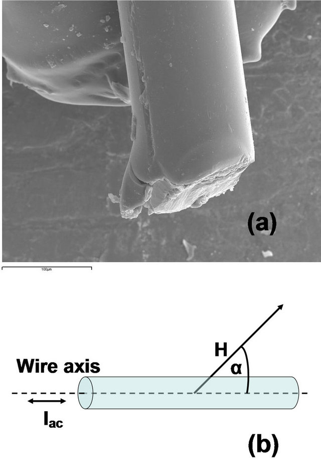
Figure 1. Cu98Be2/Fe20Co6Ni74 electroplated wire: photo was taken in secondary electron SEM regime. The wire was twisted and cut in order to separate Fe20Co6Ni74 magnetic shell from non-magnetic CuBe wire-substrate (a); external magnetic field and high frequency current arrangement for GMI measurements (b).
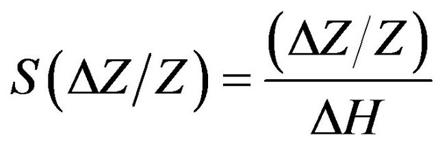 (2a)
(2a)
 (2b)
(2b)
 (2c)
(2c)
In case of the total impedance and its components the sensitivities can be also defined as follows:
 (3a)
(3a)
 (3b)
(3b)
 (3c)
(3c)
where DH = 0.2 is the change of the magnetic field. The maximum available sensitivities to a magnetic field, Smax (DZ/Z), Smax (DR/R), and Smax (DX/X) were also calculated when necessary being the maximum observed sensitivities S(Z), S(R) and S(X).
3. Results and Discussion
Figure 1 shows the cross-section of the electroplated wire which was twisted and cut on purpose to distinguish better the magnetic layer and central conductor.
The non-magnetic CuBe conducting wire and magnetic Fe20Co6Ni74 layer are clearly seen. One can evaluate the thickness of the magnetic layer as big as about 1 μm which was in a good agreement with the estimation data taken from the deposition time.
Analysis of VSM measurements and structural studies were consistent to each other indicating thickness of 1 μm for magnetic layer. EDX analysis indicated that actual composition was close to Fe20Co6Ni74. Figure 1(a) explains geometry of the GMI measurements and gives the angles definition. The longitudinal magnetisation process, i.e. magnetisation process for the magnetic field applied along the wire axis (α = 0˚) and the field dependence of the GMI for smallest and highest of studied frequencies are shown in Figure 2.
For “down” branches of the magnetoimpedance one can see the broad maximum at a negative field and much narrower one in a positive field. In contrast with the Z(H) curves, the hysteresis loop of the electroplated wire have no visible peculiarities in the negative fields. The easy magnetisation direction in the as-prepared samples (not shown here) was nearly circumferential. As a result of the field annealing, the easy magnetisation axis partially rotates to the axial direction of the wire. Previous theoretical and experimental studies [4,5] considered that
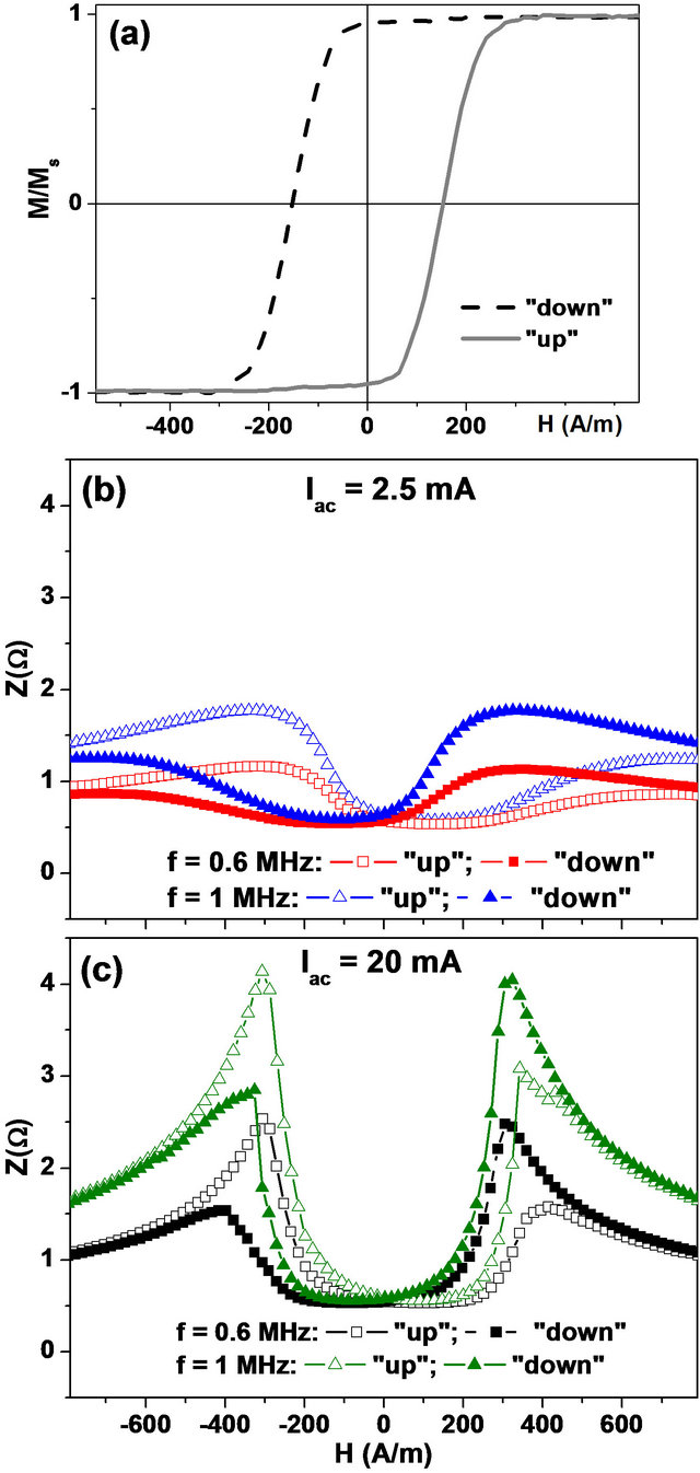
Figure 2. Inductive hysteresis loop (a) and MI responses for field annealed Cu98Be2/Fe20Co6Ni74 electroplated wire for two selected values of the driving current intensity and frequency (b). In all cases α = 0˚ (see also Figure 1(b)).
the GMI curves of this kind of wires have two differently shaped peaks corresponding to two orientation phase transitions: the broad maximum at a negative field is of the second order and much narrower one in a positive field is of the first order. This explains a significant hysteresis observed both in the positive and negative fields close to the GMI maxima (Figure 1). Although this kind of hysteresis is a disadvantage for technological applications it can be reduced either by the increase of the intensity of the alternating current [19] or by the design of double sensitive element configuration detector [22].
The impedance of the field annealed electroplated wire shows strong dependence on the magnetic field. Both the “up” and the “down” branches of Z(H) curves have two maxima in the field close to the anisotropy field of about 310 A/m estimated from the shape of the inductive hysteresis loop. Even for the smallest intensity of the driving current (Iac = 2.5 mA), rather high sensitivity of 0.82%/A/m was observed for the low frequency of 1 MHz convenient for many technological applications. The highest value of the total impedance MI ratio sensitivity (5.3%/A/m) was observed for Iac = 20 mA and f = 1 MHz which were kept for angular dependency studies of the MI response of the sensitive element. Despite of the fact that higher sensitivities were previously reported in the literature one should always compare the sensitivities obtained for different sensor elements in the same or as much as close conditions. For example, the highest sensitivity obtained by Garcia et al. [8] for FeNi/Cu wires for 1 MHz frequency was just as high as 0.038%/A/m for the wire of similar lengths and similar value of the intensity of the driving current.
Figure 3 shows the GMI variation (for total impedance, real and imaginary parts) of Fe20Co6Ni74 electroplated wire based sensitive element in external magnetic field. It is clearly seen that total impedance and its real and imaginary parts show strong and similar dependence on a magnetic field (see also Table 1): even shapes of the peaks in the positive and negative fields for R and X parts are similar to that observed for Z(H) dependence. In all cases the shape of the GMI curve can be described as characteristic two-peak response [5,16]. The maximum
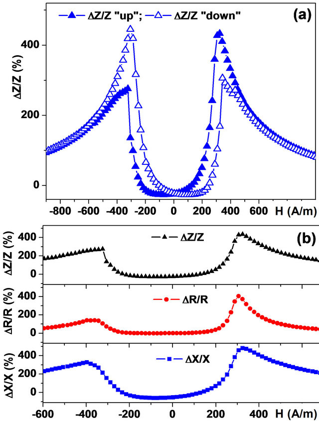
Figure 3. Field dependence of the GMI ratios for total impedance both in increasing and decreasing magnetic field (a) and total impedance, its real and imaginary parts (“down” branches) measured for field annealed FeCoNi electrodepisited wire sensitive element: Iac = 20 mA, f = 1 MHz. In all cases α = 0˚ (see also Figure 1(b)).
Table 1. Selected parameters for CuBe/FeCoNi electroplated wire based GMI sensitive element. The total impedance and it real and imaginary parts were measured for the driving current with following characteristics: Iac = 20 mA and f = 1 MHz.
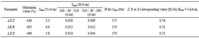
value of ΔZ/Z, ΔR/R and ΔX/X ratios were observed in the fields of 325, 310 and 335 A/m accordingly. Although the highest value of 480% was observed for ΔX/X ratio the highest sensitivity in the field range of 230 to 290 A/m corresponds to ΔR/R ratio (Table 1).
For many technological applications of magnetic field sensors the most important parameter is the sensitivity with respect to applied field for particular field interval. All measured GMI ratios were characterized by highest sensitivity in the external field of about 275 A/m being rather convenient for applications. In all cases the sensitivities were rather high (of order of 5%/A/m) and the best sensitivity of 6.6%/A/m was observed for ΔR/R ratio (if GMI ratio is considered). This shows an advantage of separate detection of the impedance components (the active resistance ΔR/R, and reactive resistance ΔX/X) comparing with usage of the total impedance ΔZ/Z as a principal detection parameter for proposed magnetic field sensor. This means that instead of increase of an intensity of the high frequency current (energy consuming option) one can simply use the separate detection strategy [3]. It is also important to emphasize that the absolute measured experimental values of the impedance and its components were in the range of about 0.52 to 0.76 Ω, i.e. they were quite similar to each other and suitable for typical semiconductor electronic component operations well adapted to present day electronic circuit requirements.
On the other hand the impedance or its component variations can be considered instead of the GMI ratios. The shape of the GMI curves allowed selection of two working intervals with high sensitivity of Z, R, and X parts (Table 1). For the low field interval 235 < H < 310 A/m the total impedance sensitivity become the highest. At the same time for the high field interval 310 < H < 325 A/m the real part of the total impedance showed the highest sensitivity.
The study of the angular dependence of the total impedance value (Figure 4 (a) showed that it is very weak if one takes into account the maximum value of Z(H) as a parameter to be detected. Z(H) for α = 0˚, 10˚, 20˚ and 45˚ are very close to each other having the value of about 4 Ω, but a decay appears for the angles below 60˚ (not shown here).

Figure 4. The angular dependencies Z(α) of the total impedance of FeCoNi electrodeposited wire based sensitive element for selected values of a magnetic field proposed as working points of a magnetic filed sensor of rotating external field (b). Field dependencies of total impedance (“down” GMI branches) for selected angles α: vertical green dashed line indicates the field of about 275 A/m in which the highest sensitivity for the angular dependence Z(α) was observed. Driving current parameters are: Iac = 20 mA, f = 1 MHz (a). Vertical arrows indicate the position of the first peak on “down” GMI branches for each one of the selected orientations.
Another one of the sensitive parameters is the value of the external magnetic field for which Z(H) reaches its maximum. Selected positions of Z(H) maxima for “down” branches (Figure 4(a)) are indicated by the arrows. Although the progress in the understanding of such a behaviour was recently reported as a simple model for composite wires [19] it is not very easy to design a magnetic field sensor on the basis of the detection of Z(H) maximum value. This would imply a number of measurements and an iteration process with different steps combined with simple analytic system. At the same time below we will show that the variation of the impedance or resistance in the field of 160 to 320 A/m can be the appropriate parameter (Figure 4) for utilization of the CoFeNi/CuBe electroplated wires to be employed as particular detectors of the orientation of the field or field rotation.
Let us select only one (“down”) GMI branch as an example and analyze the external fields H = +120, +240 or +275 A/m as possible operating points of a magnetic filed orientation detector (Figure 4 (b)). Impedance values corresponding to each operating point are collected as functions of field orientation, Z(H(α)). The highest angular sensitivity of 0.05 Ω/˚ in linear range of the angles of 0˚ to 30˚ was observed for the field of 240 A/m. For lower fields of 240 and 120 A/m the observed sensitivities in the same angular range were close to 0.023 Ω/˚ and 0.0023 Ω/˚ respectively.
The observed high angular sensitivity of the total impedance for low angles is a very important technological feature. This differs the FeCoiNi/CuBe electrodeposited wire investigated in present work from previously reported data on GMI sensors with flat geometry (thin film or amorphous/nanocrystalline ribbon based sensitive elements) [21,22] for which GMI responses are not or not sufficiently sensitive in the case of the angles α < 60˚ and especially α < 30˚.
The observed maximum of the angular sensitivity corresponds to an operating point H = 275 A/m. Such a field value is quite reasonable for technological applications. Additional studies are necessary in order to further optimize the sensitivity of the FeCoNi/CuBe wire based detector. For example, the angular dependencies of real and imaginary parts of the impedance for different frequentcies can give an additional insight. It is also worth to try different heat treatments like alternating field annealing (in order to avoid an additional destabilization of the magnetic domain structure), annealing in a magnetic field not parallel to the wire axis or stress annealing for controlling the anisotropy features.
4. Conclusion
The CuBe/Fe20Co6Ni74 composite wires for MI sensitive elements were prepared by electrodeposition of 1 μm thick FeCoNi magnetic layer onto non-magnetic substrate, followed by 1 hour annealing in an axial magnetic field of 160 A/m at a temperature of 320˚C. Very high longitudinal MI of the order of 400% was observed at a frequency of 1 MHz for Iac = 20 mA. Separate detection of the impedance components had an additional advantage: the highest value of the sensitivity of 6.6%/A/m with respect to applied filed was observed for the active resistance ΔR/R. On the other the shape of the MI curves allowed to select two working intervals with high sensitivity of Z, R, and X parts. For the low field interval of 240 to 310 A/m the total impedance sensitivity became the highest (1 Ω/Oe). Very high and linear sensitivities up to 0.05 Ω/˚ were observed for technologically important low angles for which GMI sensors with flat geometry are less effective.
5. Acknowledgements
Support by Ural Federal University 215 Grant is acknowledged. Selected measurements and observations were done in common services of the University of Oviedo and SGIKER services of UPV-EHU. We thank Dr. A Quintana and Dr. I. Orue for special support.
REFERENCES
- R. S. Beach and A. E. Berkowitz, “Giant Magnetic Field Dependent Impedance of Amorphous FeCoSiB Wire,” Applied Physics Letters, Vol. 64, No. 26, 1994, pp. 3652- 3654. doi:10.1063/1.111170
- H. Chiriac and T. A. Ovari, “Giant Magnetoimpedance Effect in Soft Magnetic Wire Families,” IEEE Transaction on Magnetics, Vol. 38, No. 5, 2002, pp. 3057-3062. doi:10.1109/TMAG.2002.802437
- G. V. Kurlyandskaya, D. De Cos, and S. O. Volchkov, “Magnetosensitive Transducers for Nondestructive Testing Operating on the Basis of the Giant Magnetoimpedance Effect: A Review,” Russian Jornal of Nondestructive Testing, Vol. 6, No. 6, 2009, pp. 377-398. doi:10.1134/S1061830909060023
- H. Garcia-Miquel, S. M. Bhagat, S. E. Lofland, G. V. Kurlyandskaya and A. V. Svalov, “Ferromagnetic resonance in FeCoNi Electroplated Wires,” Journal of Applied Physics, Vol. 94, No. 3, 2003, pp. 1868-1872. doi:10.1063/1.1590407
- G. V. Kurlyandskaya, N. G. Bebenin and V. O. Vas’kovskiy, “Giant Magnetic Impedance of Wires with a Thin Magnetic Coating,” The Physics of Metals and Metallogrpaphy, Vol. 111, No. 2, 2011, pp. 133-154. doi:10.1134/S0031918X11010200
- G. V. Kurlyandskaya, H. Yakabchuk, E. Kisker, N. G. Bebenin, H. García-Miquel, M. Vazquez and V. O. Vas’ kovskiy, “Very Large Magnetoimpedance Effect in Fe-CoNi Ferromagnetic Tubes with High Order Magnetic Anisotropy,” Journal of Applied Physics, Vol. 90, No. 12, 2001, pp. 6280-6286. doi:10.1063/1.1418423
- A. S. Antonov, N. A. Buznikov, A. F. Prokoshin, A. L. Rakhmanov, I. T. Iakubov and A. M. Yakunin, “Nonlinear Magnetization Reversal in Copper-Permalloy Composite Wires Induced by a High-Frequency Current,” Technical Physics Letters, Vol. 27, No. 4, 2001, pp. 313- 315. doi:10.1134/1.1370211
- D. Garcia, G. V. Kurlyandskaya, M. Vazquez, F. I. Toth, and L. K. Varga, “Infuence of Field Annealing on the Hysteretic Behaviour of the Giant Magneto-Impedance Effect of Cu Wires Covered with Ni80Fe20 Outer Shells,” Journal of Magnetism and Magnetic Materials, Vol. 203, No. 1-3, 1999, pp. 208-210. doi:10.1016/S0304-8853(99)00236-X
- J. M. Garcia, A. Asenjo, M. Vázquez, A. M. Yakunin, A. S. Antonov and J. P. Sinnecker, “Determination of Closure Domain Penetration in Electrodeposited Microtubes by Combined Magnetic Force Microscopy and Giant Magneto-Impedance Techniques,” Journal of Applied Physics, Vol. 89, No. 7, 2001 pp. 3888-3891. doi:10.1063/1.1346998
- J. Velleuer, A. G. Munoz, H. Yakabchuk, C. Schiefer, A. Hackl and E. Kisker, “Giant Magneto Impedance in Electroplated NiFeMo/Cu Microwires,” Journal of Magnetism and Magnetic Materials, Vol. 311, No. 2, 2007, pp. 651- 657. doi:10.1016/j.jmmm.2006.08.030
- A. C. Mishra, “Microstructure, Magnetic and Magnetoimpedance Properties in Electrodeposited NiFe/Cu and CoNiFe/Cu Wire with Thiourea Additive in Plating Bath,” Physica B: Condensed Matter, Vol. 407, No. 6, 2012, pp. 923-934. doi:10.1016/j.physb.2011.11.033
- F. E. Atalay and S. Atalay, “Giant Magnetoimpedance Effect in NiFe/Cu Plated Wire with Various Plating Thicknesses,” Journal Alloys and Compounds, Vol. 392, No. 1-2, 2005, pp. 322-328. doi:10.1016/j.jallcom.2004.09.024
- K. Favieres, C. Aroca, M. C. Sanchez, K. V. Rao and V. Madurga, “Giant Magnetoimpedance in Twisted Amorphous CoP Multilayers Electrodeposited onto Cu Wires,” Journal of Magnetism and Magnetic Materials, Vol. 196, 1999, pp. 224-226. doi:10.1016/S0304-8853(98)00775-6
- P. Jantaratana and C. Sirisathitkul, “Effects of Thickness and Heat Treatments on Giant Magnetoimpedance of Electrodeposited Cobalt on Silver Wires,” IEEE Transactions on Magnetics, Vol. 42, No. 3, 2006, pp. 358-362. doi:10.1109/TMAG.2005.863270
- F. E. Atalay, H. Kaya and S. Atalay, “Magnetoimpedance Effect in Electroplated NiFeRu/Cu Wire,” Journal of Physics D: Applied Physics, Vol. 39, No. 3, 2006, pp. 431- 436. doi:10.1088/0022-3727/39/3/001
- G. V. Kurlyandskaya, A. García-Arribas and J. M. Barandiaran, “Advantages of Nonlinear Giant Magnetoimpedance for Sensor Applications,” Sensors and Actuators A, Vol. 106, No. 1-3, 2003, pp. 234-239. doi:10.1016/S0924-4247(03)00174-2
- M. T. Tung, D. V. A. Dung, N. D. Long and A.-T. Le, “Effects of Electrolytic Current Density on Structural, Magnetic Properties and GMI Behavior in Electrodeposited Bilayer FeNi/Cu Composite Wires,” Journal of Superconductivity and Novel Magnetism, Vol. 25, No. 7, 2012, pp. 2499-2505. doi:10.1007/s10948-012-1677-z
- K. Mohri, T. Uchiyama and L. V. Panina, “Recent Advances of Micro Magnetic Sensors and Sensing Application,” Sensors and Actuators A, Vol. 59, No. 1-3, 1997, pp. 1-8. doi:10.1016/S0924-4247(97)80141-0
- P. Jantarantana, N. G. Bebenin and G. V. Kurlyandskaya, “Magnetoimpedance and Magnetization Processes of FeCoNi Electroplated tubes,” Journal of Applied Physics, Vol. 105, No. 1, 2009, pp. 013908-013914. doi:10.1063/1.3054365
- G. V. Kurlyandskaya, J. M. Barandiaran, M. Vazquez, D. Garcia and N. V. Dmitrieva, “Infuence of Geometrical Parameters on the Giant Magnetoimpedance Response in Amorphous Ribbons,” Journal of Magnetism and Magnetic Materials, Vol. 215-216, 2000, pp. 740-742. doi:10.1016/S0304-8853(00)00274-2
- M. Yamaguchi, M. Takezawa, H. Ohdaira, K. I. Arai and A. Haga, “Directivity and Sensitivity of High-Frequency Carrier Type Thin-Film Magnetic Field Sensor,” Sensors and Actuators A, Vol. 81, No. 1-3, 2004, pp. 102-105. doi:10.1016/S0924-4247(99)00096-5
- H. Hauser, L. Kraus and P. Ripka, “Giant Magnetoimpedance Sensors,” IEEE Instrumentation & Measurement Magazine, Vol. 4, No. 2, 2001, pp. 28-32. doi:10.1109/5289.930983
NOTES
*Corresponding author.